RDI Technology M702 Digital Wireless 7in. Monitor User Manual CM642702
RDI Technology (Shenzhen) Co., Ltd. Digital Wireless 7in. Monitor CM642702
Users Manual
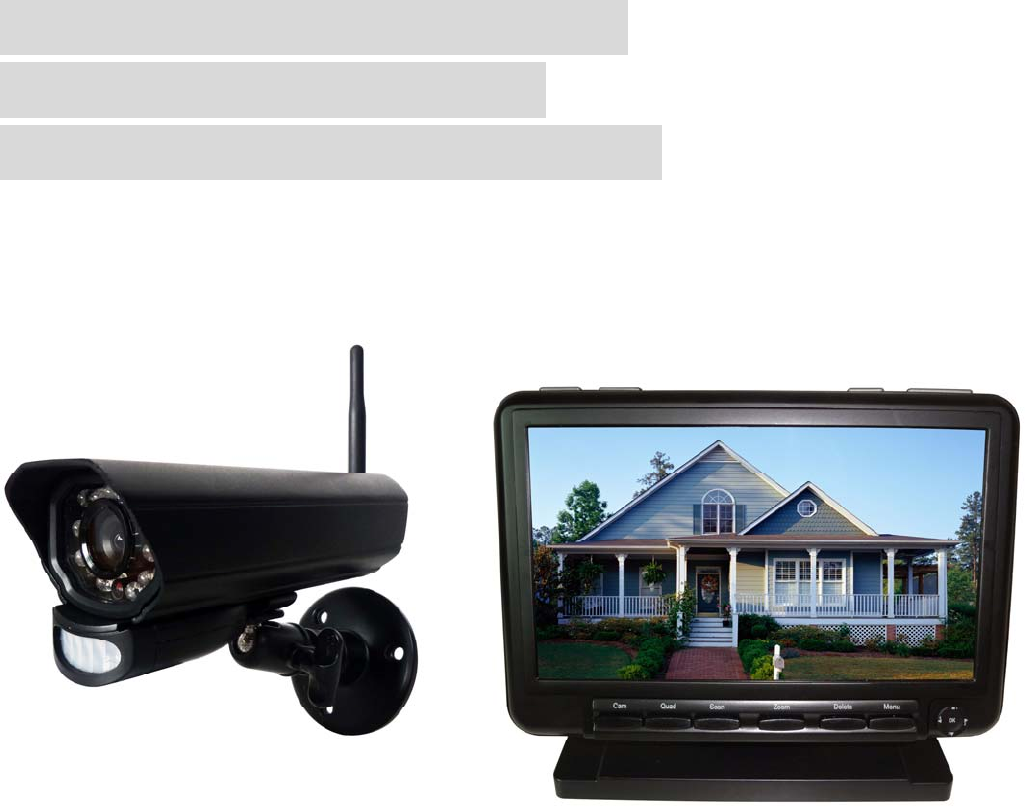
DIGITAL WIRELESS 7” LCD
MONITORING SYSTEM
WITH SD CARD RECORDING
MODEL:CM642702
Feature list:
850nm IR Led visible distance up to 10m
7” TFT Lcd Digital panel (800 RGB x 480)
Two way audio
Scan function
PIR trigger or Video motion detect recording
Manual recording
Schedule recording separate settings from Monday to Sunday
SD Card capacity up to 64GB
One Lcd monitor can pair four cameras
Frame rate: Cam x 2 : 720p x1 @ 15 fps or Cam x 2 : VGA x2 @ 30 fps or Cam x 4 : or VGA x 4 @ 15 fps
Individual recording files
5 Seconds pre-recording
Lcd : 5v DC 2A Power adaptor (+/-5%)
Camera: 9v DC 600mA (+/-5%)
RF range: 150 meter (Line of sight)
Quad view
PIR trigger and Video motion detect alert
Remote view and playback by Android or iOS smart phone
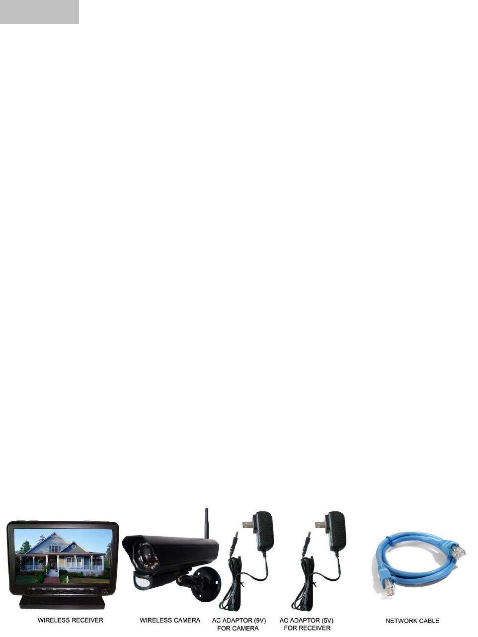
The system includes the following components:
Wireless Receiver
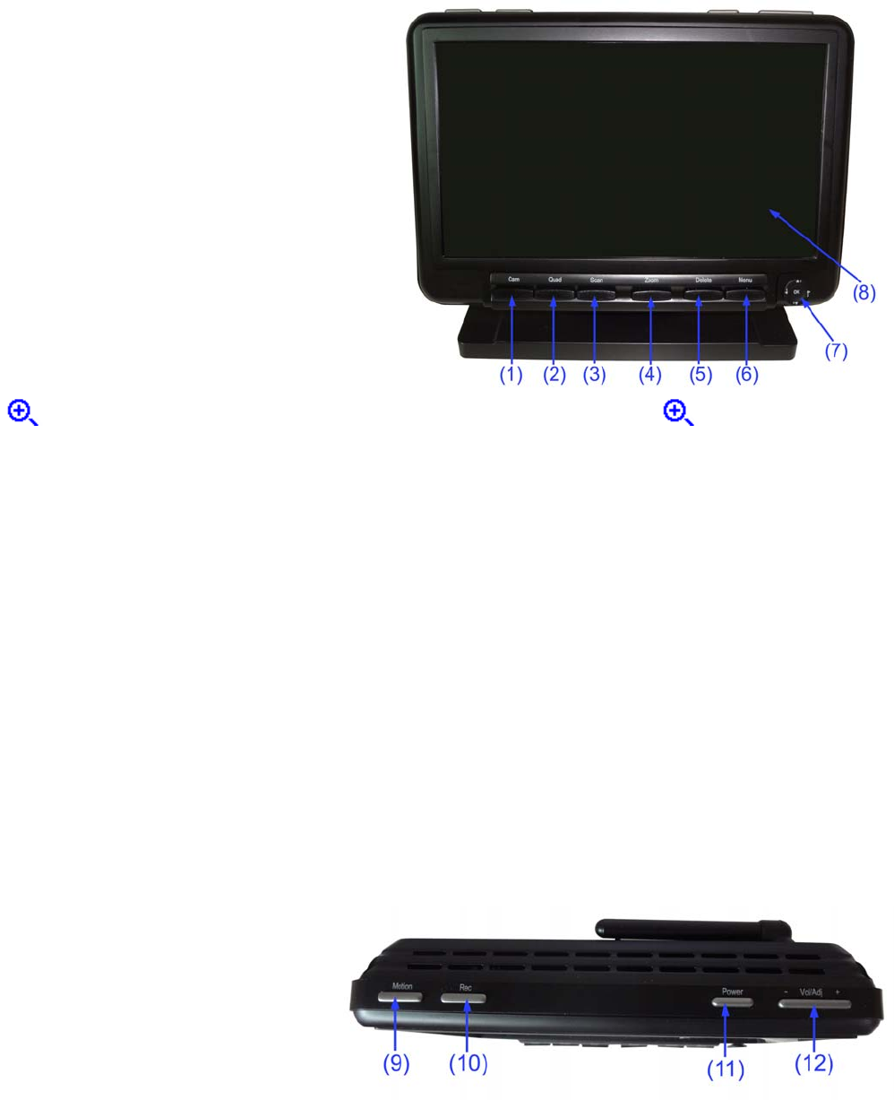
Front Controls
1. Cam--- Press the button to view cameras in
automatic switching mode.
2. Quad---- Press Quad button to view the images
in quad mode. Press Quad buttons to exit from quad
mode to automatic switching mode
3. Scan--- Press the button to switch the receiver to
scan mode. When there’s motion detected by
cameras, the LCD will lighten up and show the live
video from the camera.
4. Zoom---- In “×1” mode, press to enter “×2”
mode, shows on the screen; In “×2” mode, press it again to enter “×1” mode, doesn’t
show on the screen.
5. Delete---- Press it to delete the video.
6. Menu---Press Menu button to access the receiver menu. Press the key again to exit.
7. Joystick---
A. Navigation button (▲▼◄► arrows): servicing button
B. Enter button: Push to enter Playback mode.
8. LCD Screen--- Displays video from the camera(s) or displays system operations.
Top Controls
9. Motion--- Press this button to enter auto
recording mode. Receiver starts to record
when there is motion detection in camera
side.
10.Rec---Press this button and receiver starts
to record manually.
11. Power---Press this button to power on/off the receiver.
12. Vol/Adj---- Press the left part to decrease the volume and press the right part to increase the volume.
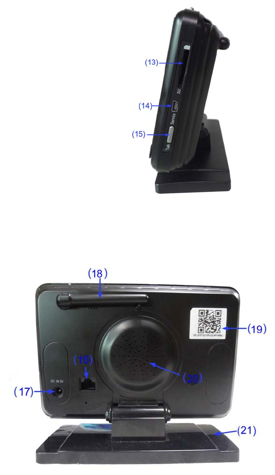
Side Controls
13. SD card slot---- Insert SD card to this SD card slot for both video
and audio recording.
14. Service--- Used for service purposes only.
15. Talk----Press this button to talk back to the camera and the icon is
displayed on the screen.
Back Controls
16. Ethernet Port (RJ45)--- Connect the
receiver to your router using the included
Ethernet cable to enable smartphone /
tablet connectivity.
17. DC 5V Power Input –-- Connect the
included DC 5V/2A power adaptor to
power the receiver.
18. Antenna---- Position the antennas as
needed for best reception.
19. Stratus UID Number / QR Code---
Unique ID number for connection to the
system on a smartphone / tablet.
20. Speaker –---Produces the sound transmitted from the camera(s).
22.Monitor stand
Wireless Receiver Installation
1. Before receiver installation, choose one installation method from below 2 methods:
1). Desktop or table stand.
For this method, you only need to place the receiver on a desktop.
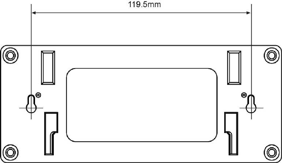
2). Wall mounting
Decide where to mount the receiver first. Make sure the range between the position and the nearest
power output port is no more than 5 feet. Also, the range between the position and TV or VCR/DVR
should be no more than 5 feet.
Drill two holes on the wall where you decide to install the receiver. Insert a plastic anchor to each hole
and fix a screw into the plastic anchor. Insert the screws into the two holes located on the bottom of
receiver and then push down the receiver.
Adjust the receiver for best viewing angle.
2. After the receiver is well positioned, plug the AC adaptor power output cable into the 5V POWER input
of the receiver, and plug the power plug into a wall outlet or surge protector.
3. If you wish to view the receiver images on a larger screen, connect one end of the included AV cable
to the AV output of receiver, and connect the other end to the Video IN (Yellow) and Audio IN (White)
ports on the TV, VCR or other viewing/recording devices.
Note: When outputting Audio/Video to TV, etc, press the AV button on the remote control to output audio
and video to TV.
The receiver installation is now completed.
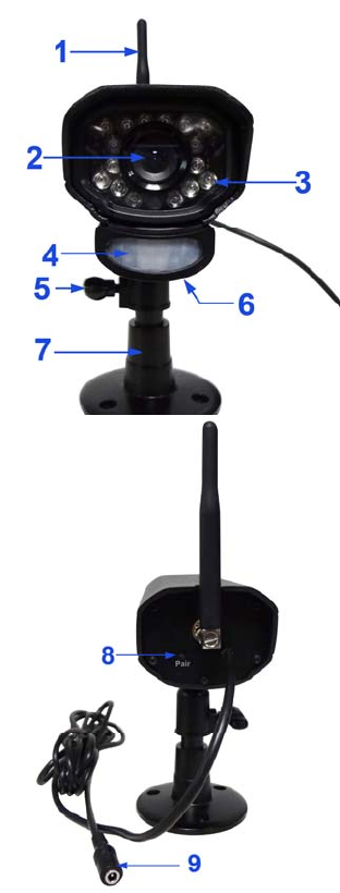
Wireless Camera
1. Camera Antenna
–Receives
&
Sends signals to or
from
the
Receiver.
2. Lens – Catches the video in front of the lens and transmits video
from camera to receiver.
3. IR LED
–Infrared
LEDs
provide viewing
in
no/low
light
conditions.
4. PIR sensor
–
Detects motion in front of the lens and emits
detection signal to transmitter.
5. Thumbscrew
-Rotates the thumbscrew to adjust the angle of the
camera until the desired view is set
6. Speaker-
Produces the sound transmitted from the monitor.
7.
Bracket
–
Use the bracket to mount the camera on a wall or other
flat surfaces.
8.
Pairing Button
–The
pairing
button
is
located
on
the back
of
the
camera
behind by
the
stand mount.
9. Power Jack
–Connect
the
DC
5V
Power Adaptor to
the
Camera.
Note: This camera includes an Auto Mechanical IR Cut Filter. When
the camera changes between day mode and night vision mode, an
audible clicking noise may be heard coming from the camera. This
clicking is normal, and indicates that the camera filter is working.
Camera Installation
Before
you
install
the
camera,
carefully
plan
where
and
how
it
will
be
positioned,
and
where
you
will
route
the
cable
that
connects
the
camera
to
the
power
adaptor.
Before
starting
permanent
installation,
verify
its
performance
by
observing
the
image
on
the receiver
when
camera
is
positioned
in
the
same
location/position
where
it
will
be
permanently installed
and
the
receiver
is
placed
in
the
location
where
it
will
be
used
most
of
the
time
Installation Warnings:
Aim
the
Camera(s)
to
best
optimize
the
viewing
area:
Select
a
location
for
the
camera
that provides
a
clear
view
of
the
area
you
want
to
monitor,
which
is
free
from
dust,
and
is
not
in
line-of-sight
to
a
strong
light
source
or
direct
sunlight.
Avoid
installing
the
cameras
where
there
are
thick
walls,
or
obstructions
between
the
Cameras and
the
Receiver.
Night Vision
This
camera
has
built-in
IR
LEDs,
which
provides
the
camera
with
the
ability
to
view
images in no/low
light conditions. It is important to use the provided power adaptor when using the camera for prolonged
periods in low light conditions, as the built-in IR LEDs will drain power more quickly than regular
daytime use.
Night vision will be automatically switched on in low illumination condition.
1. Carefully
unpack
the
Camera.
NOTE:
If
you
are
installing
Cameras
that
did
not
come
with
the
system,
please
see
the
Pairing
Camera
section
of
this
manual
for
details
on
installation.
2.
Mount
the
camera
to
the
wall:
Mark the position of the screw holes on the wall, drill holes and insert the supplied 3 plastic anchors, then
firmly fix the camera bracket to the plastic anchors with supplied screws.
NOTE:
The
camera
can
also
be
placed
on
a
flat
surface,
such as a Table
or
Shelf,
and
no
mounting
hardware
is
required.
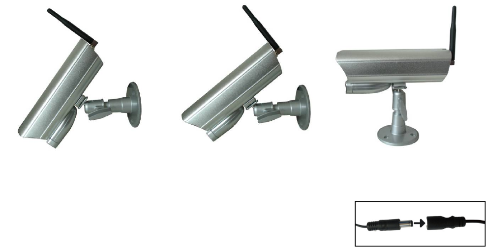
3.
Adjust
the
Viewing
angle
of
the
Camera.
You can adjust the viewing angle to monitor desired area by rotating the camera bracket. Here are some
templates:
Connecting Camera Power
After the camera is installed, plug the AC adaptor power output cable into
the 9V POWER jack of the camera, and plug the power plug into a wall
outlet or surge protector.
NOTE: You can install additional cameras (maximum of 4 cameras). When adding cameras that were
not included in the original box, you will need to pair the cameras with the receiver. Refer to the camera
pairing section of this manual.
Make sure is the DC 9V for camera, and DC 5V for Receiver
Make sure the power adaptor is placed into a grounded outlet or surge bar to protect the camera from
power fluctuations.
1 Using the system
By default, the camera(s) included with your system are automatically paired to the receiver. The
camera(s) and receiver will communicate with each other once they are powered on.
Note: It is recommended to power on the cameras before powering on the receiver.
1.1 Understanding the On-screen Display
With camera 1 properly connected and powered on, the system displays a full-screen live view of the
camera.
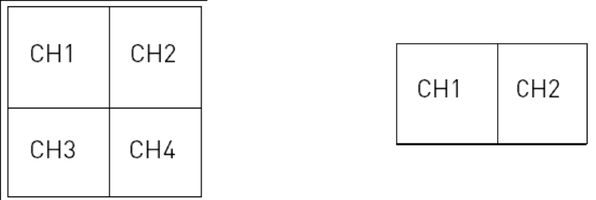
With more than one camera properly connected and powered on, the system displays up to 4 channels
in split screen with the live view of each camera. The figure below shows the display configuration for 2
cameras connected.
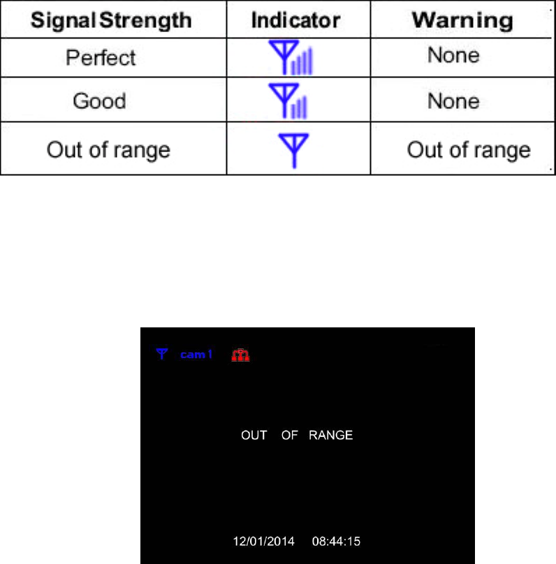
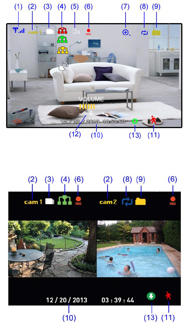
1 Signal Indicator –The signal indicator shows the strength of the signal being received from the
camera. The number of bars in the Signal Indicator shows the strength of the signal. One, or no bars
indicates the signal is poor, and 4 bars indicate a very strong signal.
Note
• If the signal is low (e.g.,1 or 2 bars) adjust the antennas, or reposition the cameras or receiver for
best performance.
• The signal indicator is not shown during Quad mode.
Signal Indicators:
OUT OF RANGE Warning
When the receiver can’t get signal from cameras, warning message will be displayed. Reposition the
camera, or check the camera power connection.
2 Channel Indicator–Displays the current channel number you are presently viewing. If viewing
multiple cameras at once, the camera indicator will appear above each video display. Press Cam to
switch between available cameras.
Note: In auto switch mode, press Quad to enter quad mode.
3 SD Card Indicator – When a SD card is inserted into the SD card slot, the indicator will be shown on
the LCD screen. A white icon shows that a SD card with available recording space is inserted in the
receiver. A red icon indicates the SD card is full.
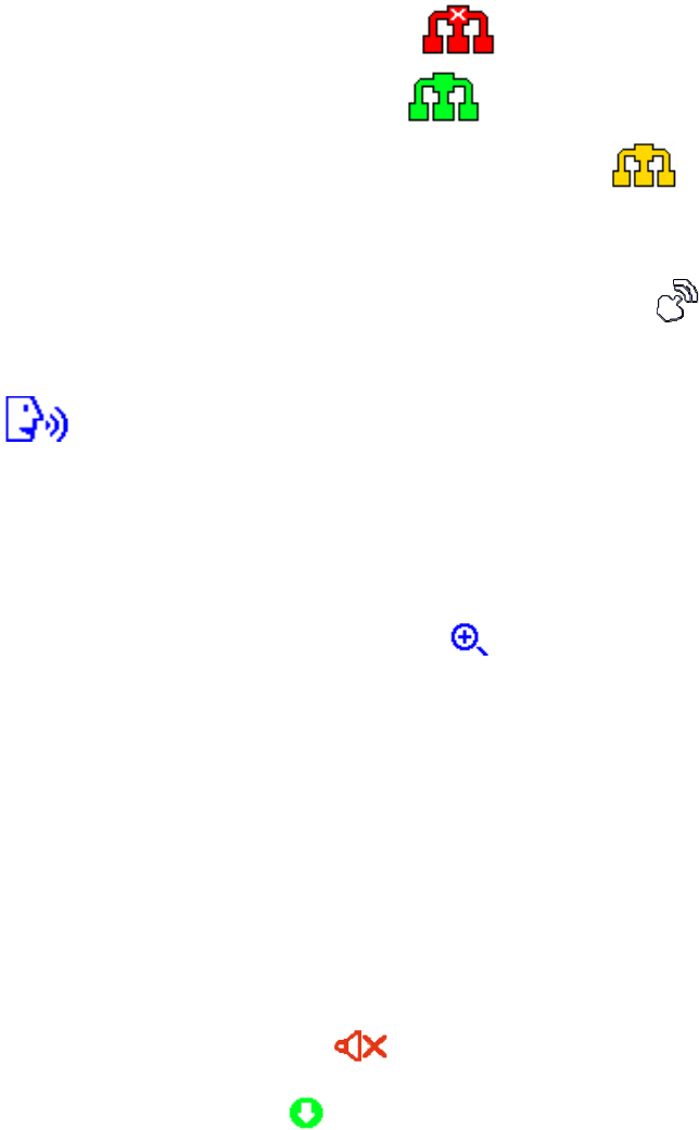
4 Network status Indicator –A red icon shows that the connection has failed or the system is
not connected to a network.A green icon shows that the system is connected to the Internet and
tell you the monitor connect with internet mode. A yellow icon shows that the system is connected
to the intranet and tell you the monitor connect with intranet mode.
Remote connection Indication- When a smartphone / tablet is accessing the system remotely, the
network status indicator changes to a remote connection icon .
5 Talk back Indicator- Press Talk button on the monitor then talk back to the camera, the indicator .
will be shown on the LCD screen.
6 Recording Indicator–"REC" appears when recording is in progress. If viewing and recording video
from multiple cameras at once, the recording indicator will appear above each video display where
recording is enabled
7 Zoom Indicator-Press the Zoom button on the front panel of monitor to enter “×2” mode, the
indicator will be shown on the LCD screen. shows on the screen ,you can use the joystick button
(▲▼◄► arrows)to navigate to parts of the video that are outside the range of screen. Press zoom
again to exit zoom mode.
8 Overwrite Indicator –Indicates Overwrite mode is on, which means the system will overwrite the
oldest recordings when the memory card is full. When you choose the overwrite function, the indicator
will be shown on the LCD screen
9 New Record Indicator- Indicates that there are new recordings saved to the SD card.
10 Time stamp-The current date and time on the system
11 Motion recording indicator- Indicates that motion recording is turned on.
12 Volume indicator-Shows the current volume of the receiver. You must be in single channel
viewing mode to change volume, indicate the volume 0.
13 New download icon- appears on the screen if new firmware is available
2 Viewing Modes
There are four different viewing modes available on the system: single channel viewing, Auto Sequence
Viewing mode (view individual channels automatically in sequence), Quad mode, and Scan mode.
Note: Auto Sequence Viewing mode cycles through connected channels in full-screen.
Use Quad mode to view up to four cameras simultaneously.
Use Scan mode, the receiver’s LCD screen and speaker will turn off unless motion is detected by one of
the cameras. The LCD screen turns on and displays video from the camera where motion was detected
for 15 seconds before turning off again. This conserves power and alerts you only when needed. You
can configure how much motion is needed to turn the display on in Scan mode by changing a camera’s
video motion detection settings. When exiting Scan mode, the receiver resumes live viewing in Auto
Sequence Viewing mode.
To change viewing modes:
Press Quad to select between Quad mode (half-Quad mode when only 2 cameras are connected) and
Auto Sequence viewing mode. OR Press Cam to switch between channels 1~4 in single channel view.
Quad mode half- Quad mode
Note: When you only pair a camera or set one camera on(other three is off), there is no access to see
QUAD mode.
3 SD Card Recording
The system records video to the SD card (not included). You can manually record the video at your
desire or the receiver records when there is motion detected by the cameras and under the Motion/REC
function, or schedule recording based on the scheduled you set for each camera. Before recording, you
need to insert a SD card to the SD card slot. The system can support up to 64GB SD card.
Recording Prerequisites: A SD card must be inserted into the receiver in order to record video. You
should always format the SD card prior to initial recording.
The following recording modes are available on the system: manual recording, schedule recording, and
motion recording. Record up to 4 channels at the same time.
3.1 Motion Recording
System only records when motion is detected by a camera(s).Press Motion on the top of the receiver to
start motion recording. There is a on the bottom right of corner. In this mode the receiver starts
recording prior to 5 seconds when motion detected by any activated camera. The recording time can be
set to 15s,30s or 1minitus after last detection. (Receiver support recording 4 camera at the same time in
quad mode)
Press Motion again or press Rec to stop recording, after stopping recording press Motion to cancel
automatic recording mode.
3.2 Manual Recording
,Press Rec on the top of the receiver to starts manual recording. Press the key again to stop manual
recording.
Note: In Quad view,it can continuous record from up to 4 cameras at a time.
3.3 Schedule Recording
Continuous or motion event recording from up to four cameras according to a weekly schedule. Set the
recording start time and end time, then switch on schedule recording in the menu to enable schedule
recording. In this mode the receiver records at a certain time every day.
3.4 Overwrite
Enter recording menu—overwrite—choose “yes” to activate overwrite function. Overwrite function can
automatically delete previous records when the SD card is full, and record new films.
4 Playback
Playback mode allows you to playback recorded video files from the SD card. You can view videos or
images directly on the system or by connecting the SD
card to your computer.
4.1 Video Playback
To playback recorded video on the system:
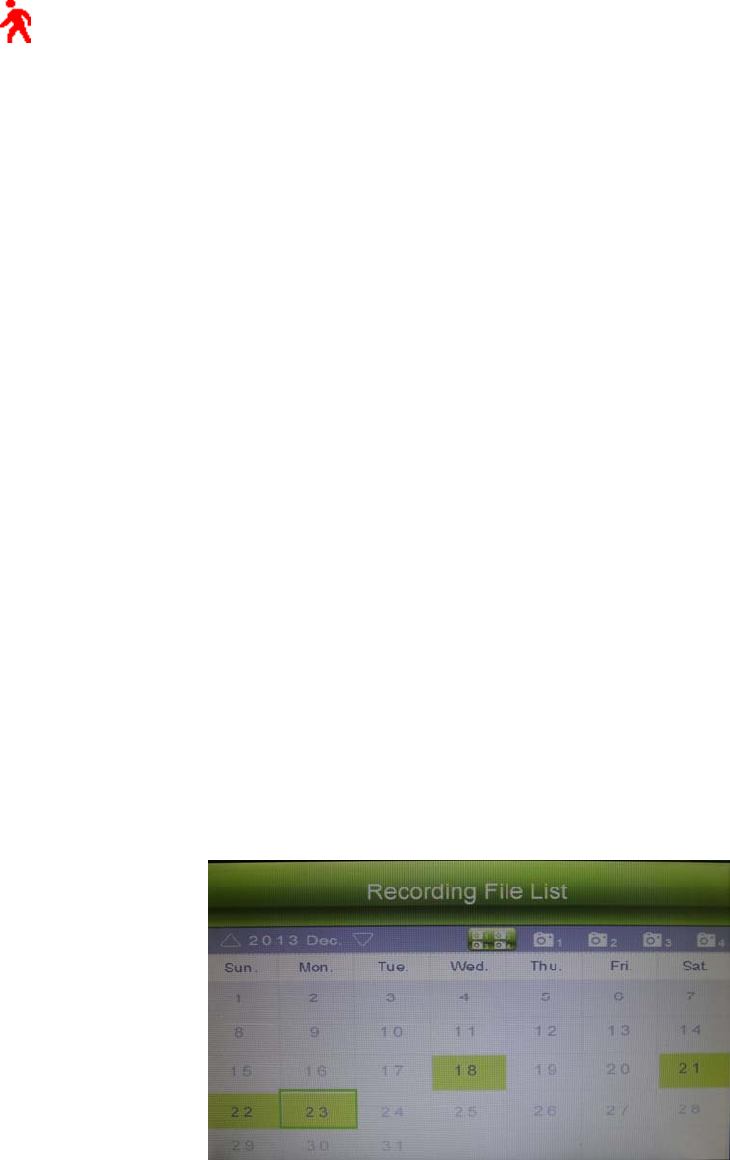
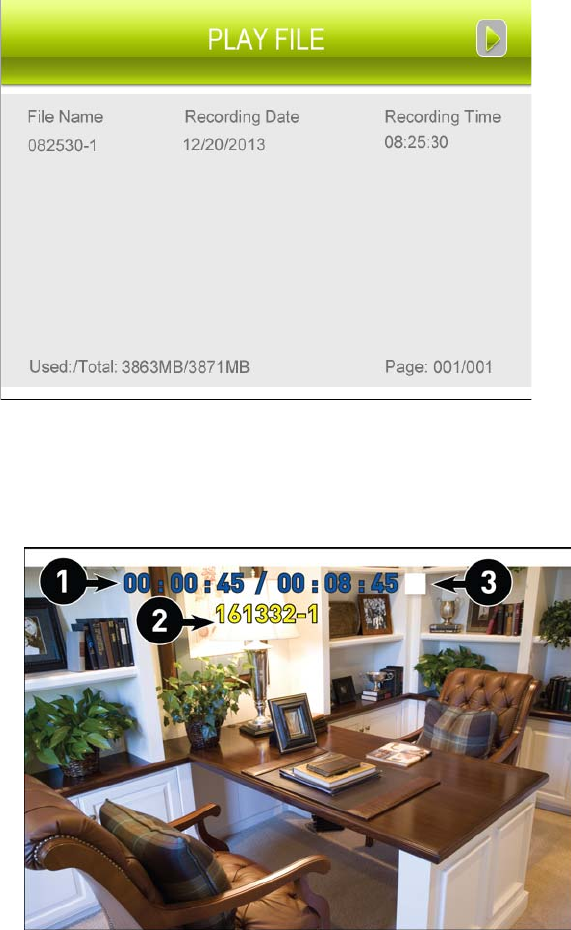
1. During live viewing, push joystick OK, The Recording
File List opens.
2. Press the joystick up / down arrow to change the
displayed month.
3.Press the joystick left/right arrow to select the
channels you would like to view recordings from:
•Press the joystick left / right arrow to select the channel numbers
•Press the joystick up / down arrow to show or hide each channel on the calendar.
• Select the button with all four channels to show recordings from all connected cameras on the
calendar.
4. Once you have selected the month and the
channels to display on the calendar, press OK to
refresh the display. Dates that have recordings
available for playback are highlighted in green.
5. Move the joystick left / right arrow to select a date
on the calendar, and press OK to view a list of
recordings for that date.
Note:
• The system uses a 24-hour clock.
• Recordings are named by start time in hhmmss
format and the channel number (for example, the
recording 133245-2 began recording at 1:32:45 PM
on channel 2).
6. Select a file from the list and press OK to confirm then the selected file loads and playback begins.
Move the joystick left / right arrow to change pages to find video files quickly.
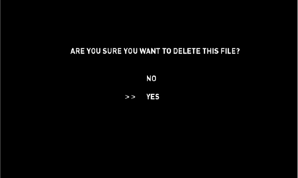
4.2 Playback controls:
1. Playback duration: Shows the length of the recording
and how much has been viewed.
2. File name
3. Playback status: Shows whether the video is playing,
paused, or stopped.
To control playback using the joystick:
•LEFT: Rewind (2x > 4x > 8x > 16x).
•UP: Pause / Play video.
•RIGHT: Fast-forward (2x > 4x > 8x > 16x).
•DOWN: Stop video.
• To change playback volume, press Volume on the
top of the receiver.
To exit playback: Press Menu to return to the file list. Press Menu repeatedly to return to live view.
4.3 Deleting Video Files
You can delete files on the SD card directly on the system. Delete files if you need to clear space on the
SD card (if file overwrite is disabled), or for your own file management purposes.
To delete files on the SD card:
1. From live viewing, press OK. The Recording File List opens.
2. Press the joystick up / down arrow to change the displayed month.
3.Press the joystick left / right arrow to select the channel numbers, and press the joystick up /down
arrow to show or hide each channel on the calendar. Select the button with all four channels to show
recordings from all connected cameras on the calendar.
4. When you have selected the month and channels to display on the calendar, press OK to refresh the
display. Dates that have recordings available for playback are highlighted in green.
5. Press the joystick left / right arrow to select a date on the calendar, and press OK to view recordings
from that date.
6. Browse to the file you would like to delete. Press the joystick UP/DOWN arrow to select the file which
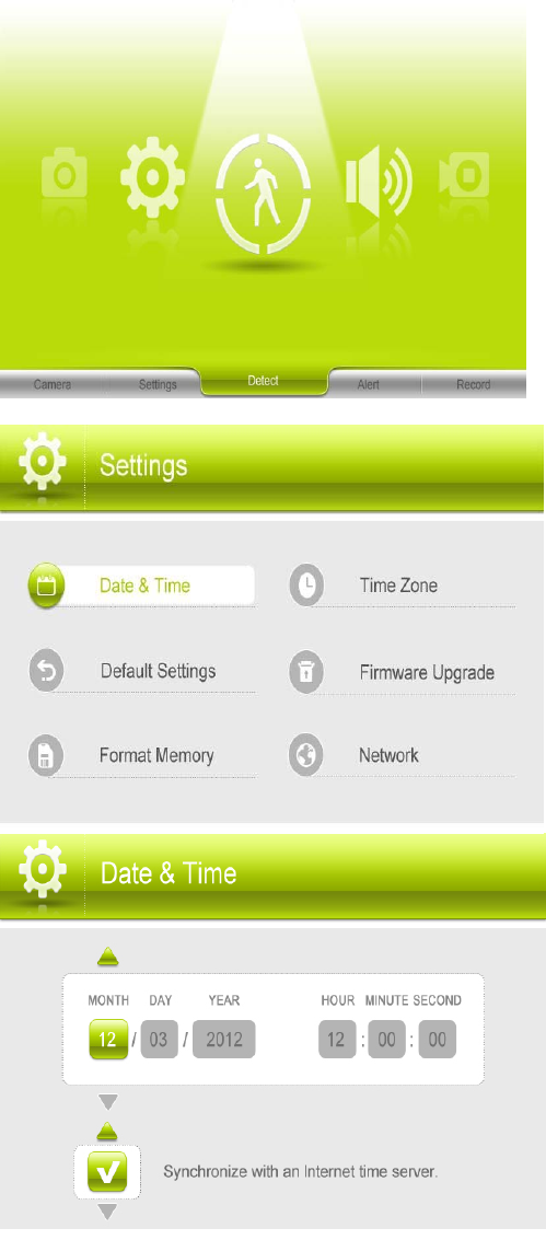
you want to delete then press Delete .
7. A confirmation message appears as below. Select YES and press OK to delete the file.
8. Repeat the steps above for other files on the SD card.
CAUTION:Do NOT delete folders on the SD card using your computer. Deleting folders may affect your
access to other files on the card or may affect normal operation of the SD card with the system. If you
want to delete the entire contents of the SD card, it is highly recommended to format the card using the
system.
Viewing Video Directly from the SD Card
You can view the saved video files on your computer (PC or Mac) by using a SD card reader (not
included). Saved video files are in ASF format.
Note:1.Some PCs and Macs may have a SD card reader built-in. Please refer to your computer's
instruction manual for more details.
2.You can view ASF files natively in Windows Media Player, as well as other media players such as VLC.
VLC is an open-source software application available at www.videolan.org
To playback recorded video on a PC:
1. Remove the SD card from the receiver by gently pushing on the SD card and then releasing. The card
will eject.
2. Insert the SD card into a SD card reader (not included) connected to your PC. Your PC should load
the SD card as a new Removable Drive and an Autorun window opens.
3. Click Open folder to view files or open the folder in Computer. Open the folder MFG.
You will then see a folder for each page of recorded video in Playback mode. Folders are named by page
number (e.g. recordings found on the second page are in the folder 00000002).
4. Double-click any of the ASF files. The video will begin playing in your default ASF media player.
5 Accessing Menu System
Use Menu on the receiver to access to Menu system.
Use the joystick to navigate up/down/left/right in the menu, and push the joystick OK to confirm a setting
or selection.
The Main Menu contains 5 submenus:
1.Settings –Use the menu for system settings, such as
date & time ,default setting, format memory, time zone,
network and firmware update.
2. Detect–Use the menu to set Camera’s motion detect
sensitivity(Hight,Medium,Low,Off)
3. Alert– Use the menu for Receiver beeps level, to alert
you when motion detected by camera. Press the joystick
left/right to decrease/increase the volume of the audio
alarm. Press OK to confirm the adjustment.
4. Record–Use the menu for SD card recording settings.
5.Camera–Use the menu to add camera(s) to the
receiver, adjust the camera on/off, adjust the brightness,
resolution for each camera.
5.1 Settings
- Date & Time: Set the date and time on the system.
Use the joystick left/right to select the item(MONTH,DAY
YEAR,HOUR,MINUTE,SECOND), and use the joystick
up/down to set the time.
Note:You can also synchronize the system time with an
Internet time server. Ensure there is a checkmark next to
Synchronize with an Internet time server then push the
joystick to confirm.
You must keep the system connected to your
wireless network using the included Ethernet cable
to synchronize with the Internet time server.
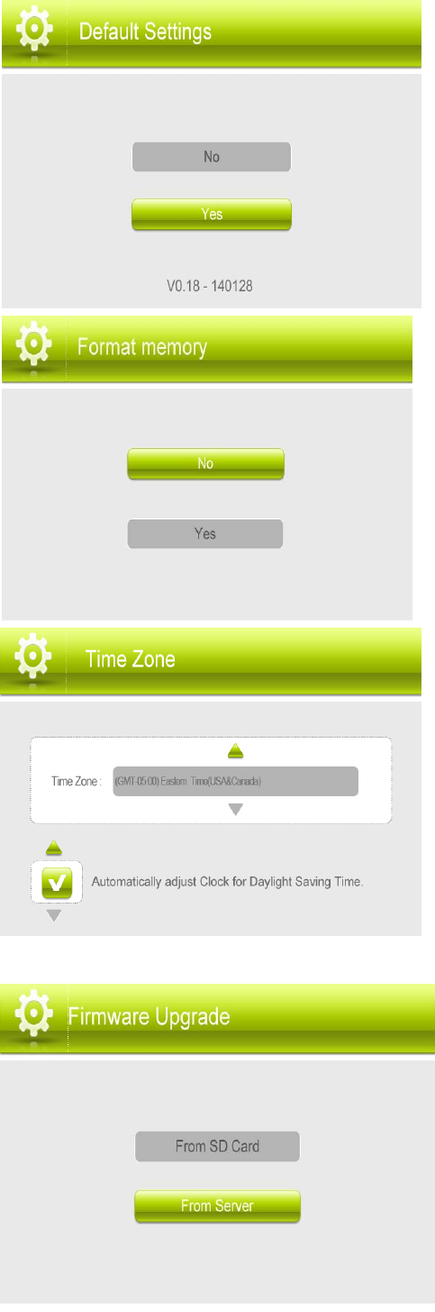
- Default Settings: Restore the system to default
settings(Default No).
Select Yes and then press OK to confirm. The system
takes a few moments to restore default settings.
Also you can see the firmware version V0.18-140128, when
you update the firmware, you can see here to confirm whether
you have done well.
NOTE: Restoring default settings does not affect files
recorded to the memory card or reset the date and time on
the system.
- Format Memory: Select Yes to format the SD card. After
formatting, all the data stored in the SD card will be
deleted.(default NO)
Note: Be cautious to use this function.
-Time Zone: Select the time zone where the system is
being used and enable / disable Daylight Savings Time
(DST).
-Firmware Upgrade: Upgrade the system’s firmware.
Ensure the system is up-to-date with the latest firmware for
optimal performance. There are two ways to upgrade
firmware: from the server, or from a SD card.
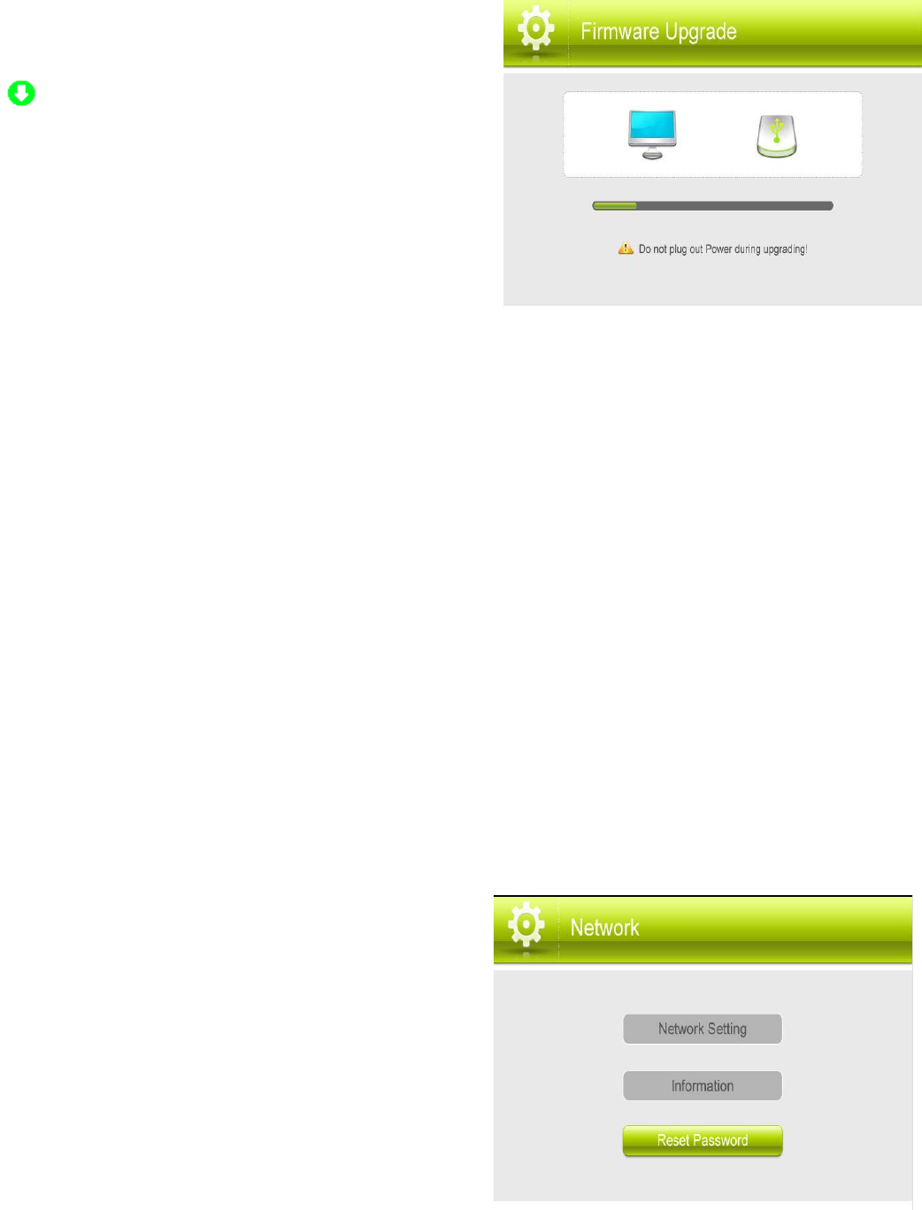
A:To update firmware from server
1. Connect the included Ethernet cable from the Ethernet
port on the receiver to your router. The new download icon
() appears on the screen if new firmware is available.
2. Press Menu, then press the joystick to select Settings.
3. Select Firmware Upgrade.
4. Select From Server, then select Yes.
The system takes a few moments to install the latest
firmware.
5. After upgrading the new firmware, the monitor will
automatically reboot .
CAUTION: During upgrading ,insure the connection of network is okay and do not plug out
power during upgrading.
B:To update firmware from SD card
1. Insert the SD card into the included adapter. Insert the adapter into the SD card reader (not included)
on your PC or Mac.
2. Download the latest firmware and transfer it to the root folder on the SD card.
3. Once the transfer is complete, insert the SD card into the card slot on the receiver.
4. Press Menu, then press the joystick to select Settings.
5. Select Firmware Upgrade and press OK to confirm.
6. Select From SD Card, then selected Yes. The system takes a few moments to install the latest
firmware.
7. After upgrading the new firmware, the monitor will automatically reboot .
CAUTION: During upgrading , do not plug out power during upgrading.
-Network: Configure the receiver’s IP address (advanced), view network information, or reset your
remote access password.
1.Netwroking setting: IP Addressing Options,to select the
Static IP and Dynamic IP
CAUTION:This section is for advanced users only.
Note
• Dynamic IP addressing is enabled by default.
• A static IP address is not required for remote access to
the system.
• You may have to configure your router settings if the
DHCP server is enabled.
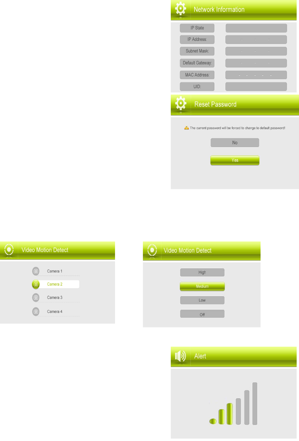
2.Information:Set up the Static IP address and Dynamic IP on/off,
display the current network information(IP State,IP Address,
default gateway, MAC address ,UID as pasted on the back of
monitor ,etc).
3.Reset password: Reset the password of remote access by
000000
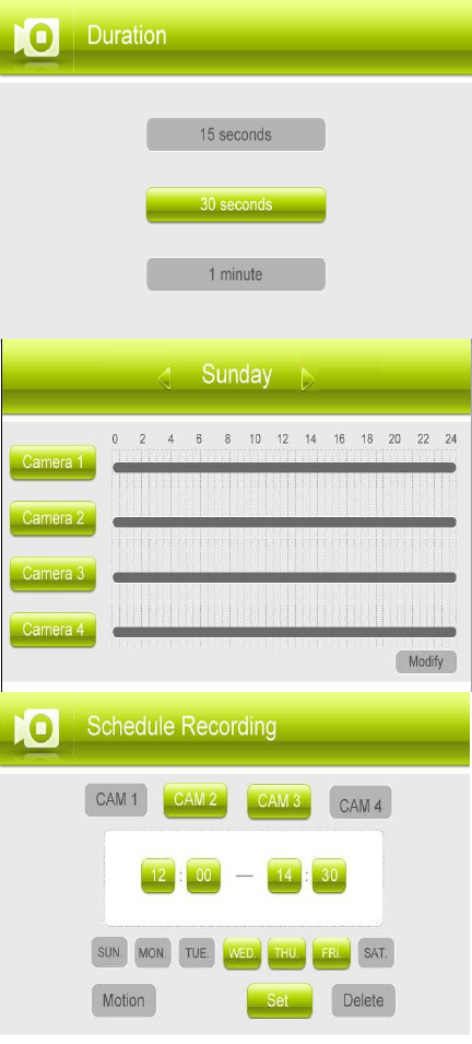
5.2 Detect
Separately to Set each Camera’s motion detect sensitivity (High, Medium, Low, Off), Press the joystick
up/down arrow to select then Press OK to confirm the adjustment.(Default Low)
5.3 Alert
Press the joystick left/right arrow to decrease or Increase the
volume of the buzzer when motion is detected by the camera(s).
If you want to turn off the buzzer sounds, turn the alert volume to
the minimum setting(Default 0)
5.4 Record
Use the Record menu to change Duration(motion recording time), set a recording schedule, and
enable/disable overwrite.
You can set up the recording parameters in record menu.
Note: To use the recording function, make sure a SD card is
inserted into the SD card slot.
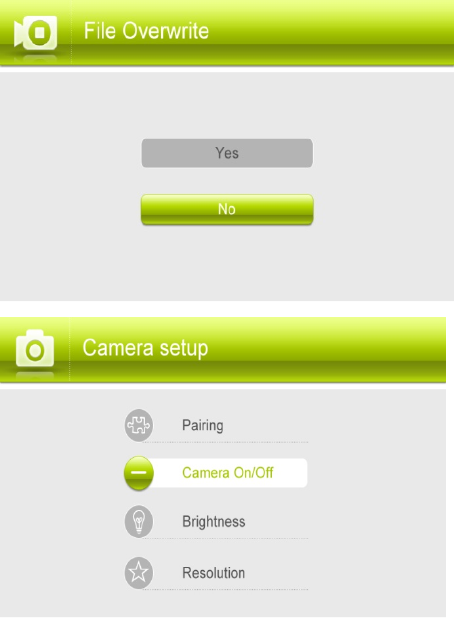
- Duration: The recording time when there is motion detected by
a camera in automatic recording mode. The recording time can
be set to 15s ,30s or 1 minute.(Default 15s)
- Schedule Recording: Use scheduled recording to have the
system automatically record continuously or based on motion
from one or more cameras according to a selected start and stop
time. Scheduled continuous recording will record constantly,
whereas scheduled motion recording will only record scenes of
movement within the scheduled recording time.
Set a recording schedule:
1. Press Menu, then select Record. Press OK to confirm.
2. Select Schedule Recording.
3. Press the joystick left / right arrow to view existing recording
schedules for each day of the week. Continuous recording
schedules appear as green bars, while motion recording
schedules appear as orange bars.
4. Press OK to create a new recording schedule.
5. Select the channels that will use this recording schedule.
Press the joystick left / right arrow to move the cursor and press
OK to include or dismiss the channel.
6. Select the start time and end time for schedule recording by
press the joystick left /right arrow to move the cursor, then press
the joystick up / down to change the values.
Note:The time uses a 24-hour clock.
7. Select which days to apply the recording schedule to by pressing the joystick left /right arrow to move
the cursor, then press OK to include or dismiss a day.
8. Press the joystcik left / right arrow to select Save, then press OK to create a continuous recording
schedule.
OR Press the joystick left / right arrow to select Motion and press OK to enable the recording schedule
for motion recording only. Select Save when finished to save your settings.
9. Press Menu until all menus are closed.
Stopping Scheduled Recording
When the stop time arrives, the system stops recording automatically. If necessary, you can stop
schedule recording manually.
To stop schedule recording: Press Rec to stop schedule recording.
Modifying or Deleting a Recording Schedule
You can modify any recording schedule by adding or subtracting recording time.
To modify /delete a recording schedule:
1. Press Menu , then select Record. Press OK to confirm.
2. Select Schedule Recording.
3. Press the joystick up / down arrow to select Modify and press OK to confirm.
4. Select which channels to change the schedule for by pressing the joystick left / right arrow to move the
cursor, then press OK to include or dismiss the channel.
5. Select the start time and end time for the modification. This could be a span of time you wish to add to
or subtract from an existing schedule. Press the joystick left / right arrow to move the cursor, then press
the joystick up / down arrow to change the start and end time.
6. Select which days of the week to apply the modification to by Pressing the joystick left /right arrow to
move the cursor, then push the joystick OK to include or dismiss a day
7. Press the joystick left / right arrow to select the type of modification:
• Select Save to add onto a continuous schedule.
• Select Motion then Save to add onto a motion schedule.
• Select Delete to subtract from either type of schedule.
8. Press Menu until all menus are closed.
Note:If you delete a recording schedule during a scheduled recording time, the camera(s) will continue
to record video for a short period afterwards. The system checks for changes in recording schedules
every half hour and will eventually stop recording if a schedule has been deleted.
- File Overwrite: Use the overwrite feature to have the system
overwrite the oldest recorded data on the SD card once the SD
card is full
5.5 Camera Setup:
Pairing :The system comes with camera(s) that have already
been paired. These cameras will communicate with the receiver
once powered on.
NOTE: It is highly recommended to pair the cameras to the receiver before permanently mounting the
cameras.
The pairing function assigns each camera to a different channel on the wireless receiver (up to 4
cameras), and is necessary for configuring additional cameras.
NOTE: It is highly recommended to pair the cameras to the receiver before permanently mounting the
cameras.
1. Power on the receiver by connecting it to power outlet with supplied 5V power adaptor.
2. Power on the camera by connecting it to power outlet with
supplied 9V power adaptor.
3. Press the Menu on the receiver. Navigate to the Pairing menu
option by pressing the joystick up/right arrow to select the
desired pairing channel. Press OK to enter the pairing operation.
4. Select a channel and press OK to confirm the selection.
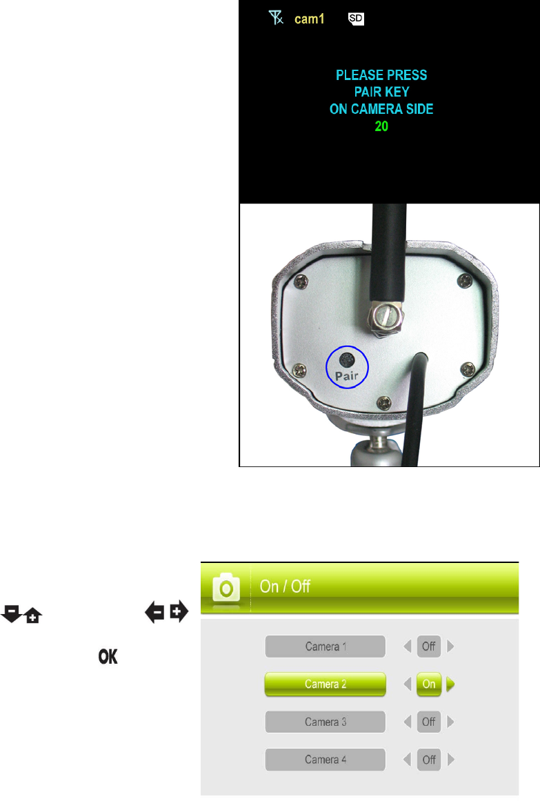
5. A message will be displayed on the receiver screen.
The receiver will count down from 30~0 – you must press the
Pair button on the camera during this time to successfully pair
the camera.If the button on the camera is not pressed, the
receiver will return to the view screen, and no pairing will take
place.
6. Following the on-screen prompt, press the Pair button on the
back of the camera. You have 30 seconds to press the Pair
button on the camera, once paired, after 3s will see the live video
on monitor .
-Camera On/Off :
Select a camera by pressing , then pressing /
to switch on or switch off the camera. Press to
confirm the change and exit.
NOTE: The currently selected camera will have On/Off
highlighted in Green. Any disabled channels will be
blacked out in Quad mode when you pair 4 cameras.
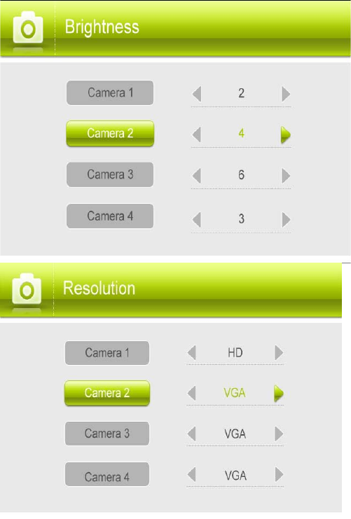
-Brightness:
Press right arrow to increase the brightness level for the
selected camera,or left arrow to decrease brightness.
Camera brightness is measured on a scale of 1-6 where
1 is the darkest and 6 is the brightest. Press OK to save
changes. (default 3)
Press UP/DOWN arrow to select your other cameras as
needed
-Resolution:
Select the frame rate for each camera by HD or VGA
Frame rate: Cam x 1 : HD(720p x1) @ 15 fps or Cam x 2 :
D1x2 @ 20 fps or Cam x 2 : VGA x2 @ 30 fps or Cam x 4 :
VGA x4 @ 30 fps, or VGA x 4 @ 10 fps
Android and iOS App Remote view
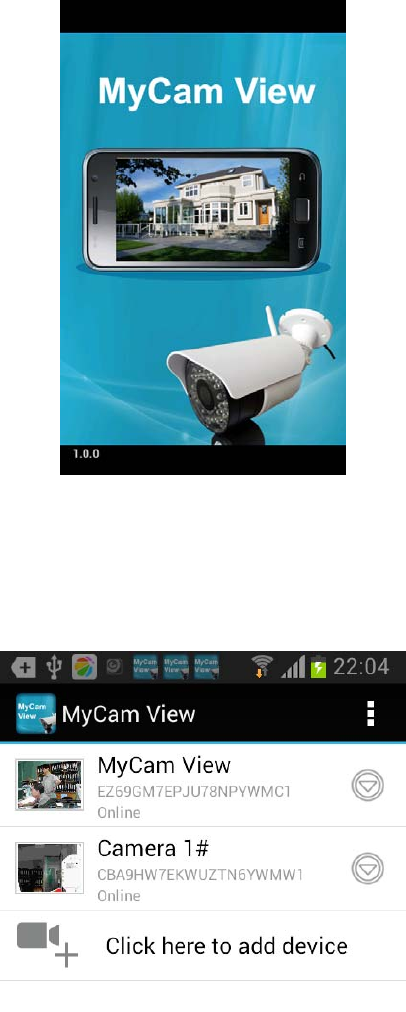
1. Download app MyCam View 1.0.0.apk freely from the App Store or the Google player
store on your smart phone or tablet.(Make sure your phone connect with network)
2. Connect the 7’’monitor with your home router by internet cable.
3. Add camera(Android APP for example)
Touch the App icon MyCam View to launch the app, Tap “Click here to add camera”
Then the right pictures as showed, there are 2 options to get the UID from the monitor.
Option A: Enter the UID printed below the
QRcode(example:D7ETGG7YPUUZUNPYWM4J) as it shows on the back of monitor.
Option B: Tap Scan button to scan the QRcode on the back of monitor.
Name: Press it to rename the camera(original name is MyCam View)what you want.
Enter the Password:000000(Default setting)
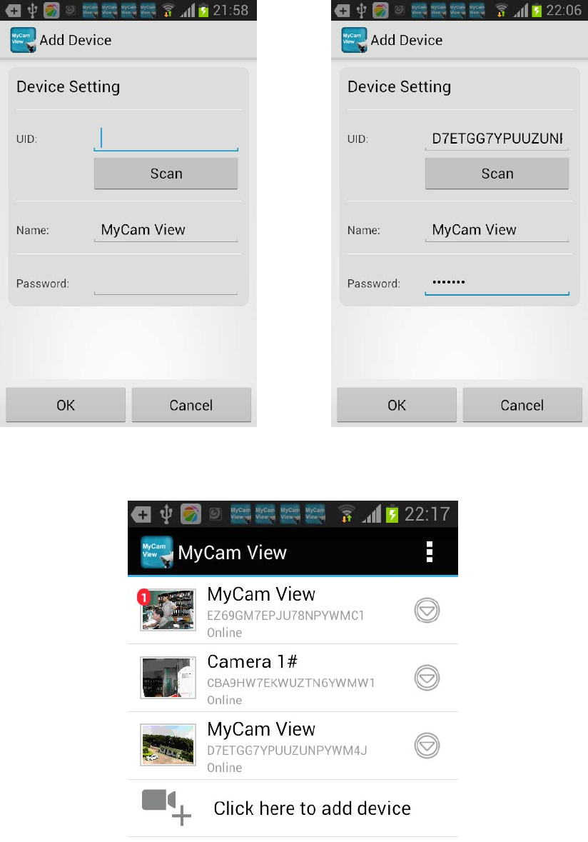
Then press OK to confirm it.
4. The system will show in your device list at an online status as below picture.
5. Press the camera you have added on your device, now you can view live video from
your camera in either portrait or landscape mode.
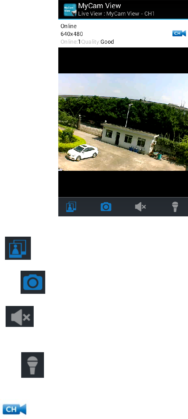
View icon : press this icon to view Snapshot photos already taken.
Snapshot Icon : press this icon to take photo from camera side
Mute Icon : It cut off the audio on the camera side.
Press this icon to listen the audio from camera side.
Talk back Icon :Press it to talk back to the camera currently being displayed on your
phone.
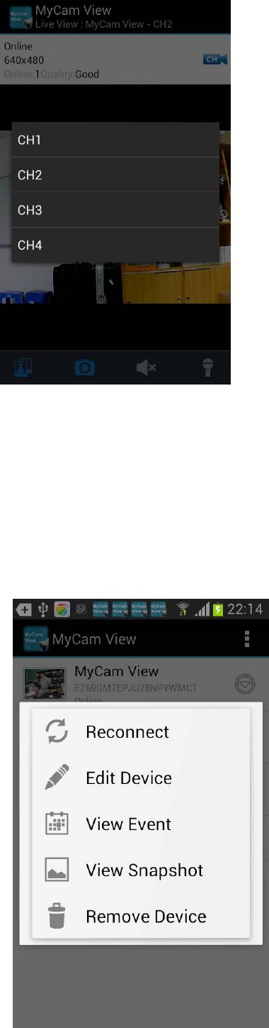
CH Icon : press this icon to change channel which you want to see.
Online:1,only one remote visit, system support 4 remote visit at the same time.
Quality: shows the network quality.
6. Back to the add camera menu, then press the down arrow,a new interface pops out as
showed .
Reconnect: If your remote device connected failed with the camera, press it to reconnect.
Edit Device: Device setting and Advanced setting are
under this menu. You can see the camera’s details
under Device Setting.
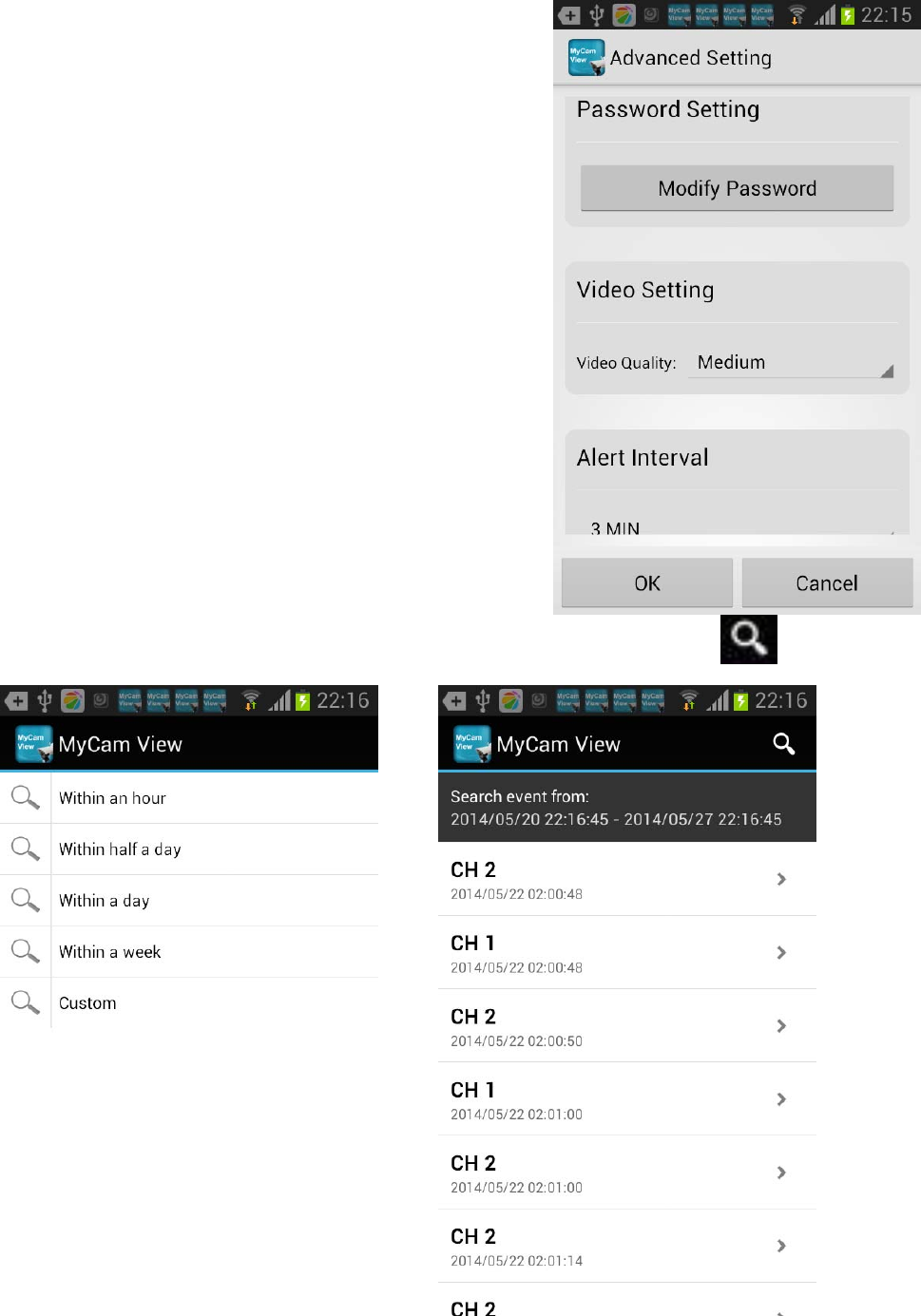
You can modify Password setting(default 000000) ,
video Quality(default Min) and Alert interval(default 3
MIN)under Advance setting.
View Event: Select it to playback the video on your
phone. You can tap icon to view live video by selecting
a period of time(within an hour, within half a day, within a day, and within a
week) or as you want by Custom time.
View Snapshot: Select it to view the photos you have taken by Snapshot key.
Remove Device: Delete this camera from your phone
FCC and IC Note:
THIS DEVICE COMPLIES WITH PART 15 OF THE FCC RULES AND INDUSTRY CANADA
LICENSE-EXEMPT RSS STANDARD(S). OPERATION IS SUBJECT TO THE FOLLOWING TWO
CONDITIONS: (1) THIS DEVICE MAY NOT CAUSE HARMFUL INTERFERENCE, AND (2) THIS
DEVICE MUST ACCEPT ANY INTERFERENCE RECEIVED, INCLUDING INTERFERENCE THAT
MAY CAUSE UNDESIRED OPERATION.
THE MANUFACTURER IS NOT RESPONSIBLE FOR ANY RADIO OR TV INTERFERENCE
CAUSED BY UNAUTHORIZED MODIFICATIONS OR CHANGE TO THIS EQUIPMENT. SUCH
MODIFICATIONS OR CHANGE COULD VOID THE USER’S AUTHORITY TO OPERATE THE
EQUIPMENT.
This equipment has been tested and found to comply with the limits for a Class B digital device,
pursuant to part 15 of the FCC Rules. These limits are designed to provide reasonable
protection against harmful interference in a residential installation. This equipment generates,
uses and can radiate radio frequency energy and, if not installed and used in accordance with
the instructions, may cause harmful interference to radio communications. However, there is no
guarantee that interference will not occur in a particular installation. If this equipment does
cause harmful interference to radio or television reception, which can be determined by turning
the equipment off and on, the user is encouraged to try to correct the interference by one or
more of the following measures:
-- Reorient or relocate the receiving antenna.
-- Increase the separation between the equipment and receiver.
-- Connect the equipment into an outlet on a circuit different from that to which the receiver is
connected.
-- Consult the dealer or an experienced radio/TV technician for help.
To maintain compliance with FCC’s RF exposure guidelines, this equipment should be installed
and operated with a minimum distance of 20cm between the radiator and your body.