RDI Technology M710 DIGITAL WIRELESS MONITOR User Manual CMD6371SR Manual
RDI Technology (Shenzhen) Co., Ltd. DIGITAL WIRELESS MONITOR CMD6371SR Manual
Users Manual
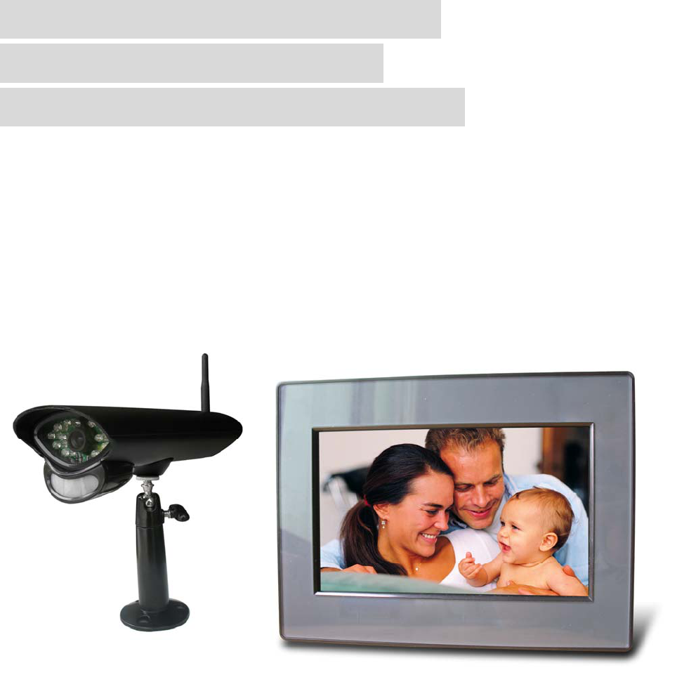
DIGITAL WIRELESS 7” LCD
MONITORING SYSTEM
WITH SD CARD RECORDING
INSTRUCTION MANUAL
Manual
1
Features
• Digital wireless technology provides excellent image quality and clarity
• Interference free, secure and private signal
• Up to 300ft wireless transmission range ①
• Two-way audio communication
• SD card recording
• Safety warning feature notifies you when out of range
• System expandable up to 4 cameras ②
① Maximum open space transmission range. The actual range is dependent upon building
materials and other obstructions in path of wireless signal.
② Additional cameras sold separately.
Camera Features
• VGA resolution camera
• Night vision allows for low light viewing up to 15 feet / 4.5 meters ③
• Built-in microphone
• Weatherproof for outdoor use
• PIR Sensor for motion detection
③ IR illumination range of 15ft./4.5m under ideal conditions. Objects at or beyond this range
may be partially or completely obscured, depending on the camera application.
Receiver Features
• 7” color LCD monitor/receiver with superior image quality
• Auto recording, manual recording and schedule recording
• Remote control for receiver portable operation
• Displaying stored pictures in scan mode (screen saver)
• Can be desktop stand or wall mounted
• Supports quad image view
Getting Started
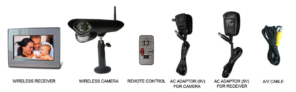
The system comes with the following components:
Check your package to confirm that you have received the complete system, including all components
shown above.
2
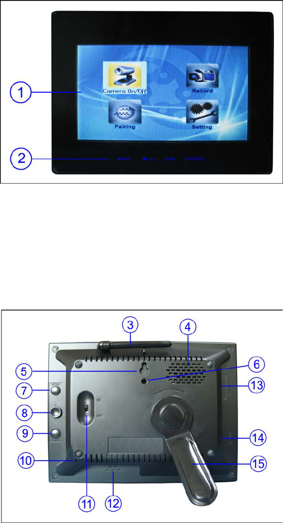
Wireless Receiver
Front Controls
1. LCD Screen – Displays video from the
camera(s) or displays system operations.
2. Indication LEDs – Indicates the status
of the system. There are 4 indication
LEDs:
NEW: Indicates new recorded video.
FULL: Indicates that the SD card is full of
memory. It is only available when
Overwrite is disabled.
SCAN: Indicates that the receiver is in
scan mode (screen saver).
AUTO REC: Indicates that the receiver is in auto recording mode. Receiver starts to record when there is
motion detection in camera side.
Back Controls
3. Receiver Antenna – receives & sends signals from or to the camera(s). Adjust the antenna to vertical
position when the signal reception is not good.
4. Speaker – Produces the sound
transmitted from the camera(s).
5. Hanging Hole – Insert the screw which
is already installed on a wall into the hole,
and push the receiver downwards to hang
the receiver on the wall.
6. Wall Mounting Hole – Screw the wall
mounting bracket to the hole, then fix the
bracket to the wall to mount the receiver
on the wall.
7. MENU Button – Press to access the
receiver menu. Press the button again to
exit.
8. Joystick – In viewing mode, press down the joystick to enter playback interface for recorded videos.
In quad mode, push the joystick to a certain number to view the image from the corresponding camera in
full screen mode.
In menu mode, use the joystick (UP/DOWN/LEFT/RIGHT ▲▼◄► arrows) for system setting or menu
selection, and press it down it to confirm the selection or setting.
In playback mode, use the joystick to play/pause, stop, forward, backward, etc.
3
9. TALK Button – Press down and hold this button to talk back to the camera which’s image is displayed
on the screen.
10. Microphone – Receives sounds from the area near the receiver and transmits sound from the
receiver to the camera (only when TALK Button is pressed down and held).
11. Power Slide Switch – Slide the switch to ON or OFF position to switch on/off the receiver.
12. DC 5V Power Input – Connect the included DC 5V power adaptor to power the receiver.
13. SD Card Slot – Insert SD card to this SD card slot for both video and audio recording.
14. A/V Out Port – Connect the included A/V cable to view video from the receiver on a TV or monitor, or
record to a VCR/DVR.
15. Receiver Stand – Enables the receiver to stand on a flat surface, such as a table or countertop. You
can also adjust the viewing angle by rotating the stand.
Wireless Receiver Installation
1. Before receiver installation, choose one installation method from below 3 methods:
1). Desktop or table stand.
For this method, you only need to place the receiver on a desktop and use the supplied receiver stand.
2). Hung on the screw which is fixed on a wall.
Decide where to hang the receiver first. Make sure the range between the position and the nearest
power output port is no more than 5 feet.
Drill a hole on the wall where you decide to hang the receiver, insert one plastic anchor and fix a screw
into the plastic anchor. Now the receiver can be hung on the screw (receiver back control number ⑤).
3). Wall mounting
Decide where to install the receiver first. Make sure the range between the position and the nearest
power output port is no more than 5 feet.
Screw supplied wall mounting bracket to the receiver (receiver back control number ⑥), then drill 3
holes on the wall where you decide to install the receiver, then insert 3 plastic anchors and fix the wall
mounting bracket to the anchors with supplied screws.
2. After the receiver is well positioned, plug the AC adaptor power output cable into the 5V POWER input
of the receiver, and plug the power plug into a wall outlet or surge protector.
3. If you wish to view the receiver images on a larger screen, connect one end of the included AV cable
to the AV output of receiver, and connect the other end to the Video IN (Yellow) and Audio IN (White)
ports on the TV, VCR or other viewing/recording devices.
Note: When outputting Audio/Video to TV, etc, press the AV button on the remote control to output audio
and video to TV.
The receiver installation is now completed.
4
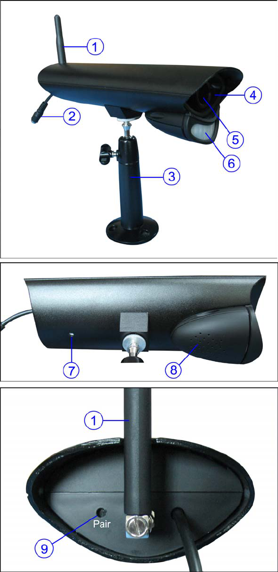
Wireless Camera
Front & Side Controls
1. Camera Antenna – Sends & receives
signals to or from the receiver.
2. AC Adaptor Jack – Plug the AC
adaptor to the jack for camera’s power
supply.
3. Wall Mounting Bracket – Use the
bracket to mount the camera on a wall or
other flat surfaces.
4. IR LEDs – Infrared LEDs provide
viewing in no/low light conditions
5. Lens – Catches the video in front of
the lens and transmits video from
camera to receiver.
6. PIR Sensor – Detects motion in front
of the lens and emits detection signal to
transmitter.
Bottom Controls
7. Microphone – Receives sounds from
the area near the camera, and transmits
sound from the camera to the receiver.
8. Speaker – Produces the sound
transmitted from the receiver.
Back Controls
9. Pair Button – The pair button is
located on the back of the camera, it is
used to pair the camera with receiver.
Camera Installation
Before you install the camera, carefully plan where and how it will be positioned, and where you will
route the cable that connects the camera to the power adaptor.
Before starting permanent installation, verify its performance by observing the image on the receiver
when camera is positioned in the same location/position where it will be permanently installed and the
receiver is placed in the location where it will be used most of the time.
5
Installation Warnings
Aim the camera(s) to best optimize the viewing area: Select a location for the camera that provides a
clear view of the area you want to receiver, which is free from dust, and is not in line-of-sight to a strong
light source or direct sunlight.
Avoid installing the cameras where there are thick walls, or obstructions between the cameras and the
receiver.
Night Vision
This camera has built-in IR LEDs, which provides the camera with the ability to view images in no/low
light conditions. Night vision will be automatically switched on in low illumination condition.
Installing the Camera
1. Carefully unpack the camera.
NOTE: If you are installing cameras that did not come with the system, please see the pairing camera
section of this manual for installation details.
2. Mount the camera to the wall.
Mark the position of the screw holes on the wall, drill holes and insert the supplied 3 plastic anchors, then
firmly fix the camera bracket to the plastic anchors with supplied screws.
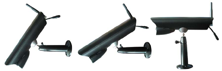
3. Adjust the viewing angle of the camera
You can adjust the viewing angle to monitor desired area by rotating the camera bracket. Here are some
templates:
4. Connect camera power
After the camera is installed, plug the AC adaptor power output cable into the 9V POWER jack of the
camera, and plug the power plug into a wall outlet or surge protector.
NOTE: You can install additional cameras (maximum of 4 cameras). When adding cameras that were
not included in the original box, you will need to pair the cameras with the receiver. Refer to the camera
pairing section of this manual.
Camera installation is now completed.
6
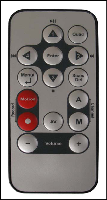
Remote Control
The remote control is supplied to operate the receiver. It includes all the operations on the receiver
except talking back to camera.
Note: When using remote control, it is recommended to have it point at the IR reception port which is
above the LCD screen.
Quad – Press Quad button to view the images in quad mode.
Press (Channel) A, (Channel) M or Quad button again to exit
from quad mode.
Menu –Press to access the receiver menu. Press the button again
to exit.
Enter – In viewing mode, press to enter playback interface for
recorded videos.
Navigation/Enter – Use the buttons to control the receiver in
Quad Mode, Menu Mode and Playback mode.
- Quad Mode: In quad mode, press a navigation button to view
the image from the corresponding camera in full screen mode.
- Menu Mode: Use the navigation buttons to navigate in Menu
Mode. Press the Enter button to confirm the menu selection.
- Playback Mode: In playback mode, use the navigation buttons
to play/pause, stop, forward, backward.
Scan/Del – In viewing mode, press the button to switch the
receiver to scan mode. In scan mode the LCD screen is turned off
or displays a static picture, and the system continuously scans all available cameras. The indication LED
SCAN below the LCD screen will be on.
If motion is detected by the camera(s), the receiver will beep and display the image from the triggered
camera. The receiver will return to scan mode about 5 seconds after the alarm has completed. Press
Scan, (Channel) A or (Channel) M buttons will cancel scan mode.
In playback interface, press the button to delete recorded files from SD card.
(Record) Motion – Press the button to switch the system to automatic recording mode. In this mode, the
indication LED AUTO REC will be on and the receiver starts recording when motion detected by a
camera. The recording time can be set to 15s or 30s.
(Record) ● – Press the button to start recording, press it again to stop recording.
(Channel) A – Press the button to view cameras in automatic switching mode.
(Channel) M – Press the button to manually switch between all activated cameras.
AV – When connecting the receiver to TV or VCR/DVR, press the button to output audio/video. When
outputting audio and video, the LCD screen will be switched to blank.
Vol- / Vol+: Press the buttons to adjust the volume.
7
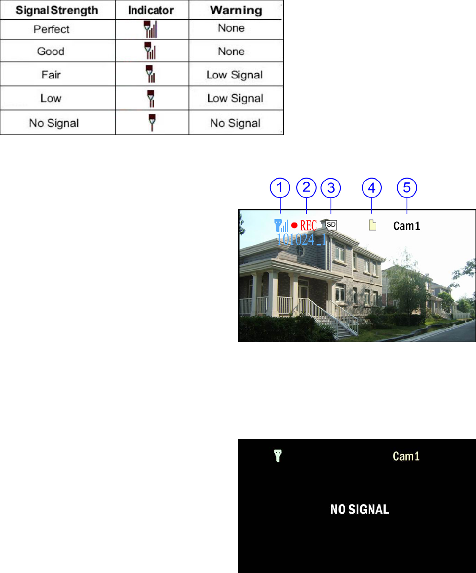
Viewing Mode
1. Signal Indicator – The signal indicator shows the strength of the signal being received from the
camera.
Signal Indicators:
2. Recording Indicator – When the receiver is recording, the red indicator ●REC will be shown on the
LCD screen. And under the indicator, you can see
the name of the recorded file.
3. SD Card Indicator – When a SD card is
inserted into the SD card slot, the indicator will be
shown on the LCD screen.
4. New Record Indicator – When there is new
recorded file, the indicator will be shown on the
LCD screen and flashes to alert users. Meanwhile,
the indication LED NEW below the LCD screen
will be on
5. Channel Indicator – Displays the current
channel number. Press the (Channel) M button on the remote control to switch between available
cameras.
Note: To automatically switch between channels, press the (Channel) A button on the remote control.
No Signal Warning
When the camera is positioned too far from the
receiver, warning message will be displayed.
No Signal: The warning appears when the
receiver can’t get access the camera. Reposition
the camera, or check the camera power
connection.
8
SD Card Recording
The system is designed for SD card recording. You can manually record the video at your desire or the
receiver records when there is motion detected by the cameras. Before recording, you need to insert a
SD card to the SD card slot. The system can support the size of up to 16GB SD card.
Recording Mode
Auto Recording
Press (Record) Motion button on the remote control to set the system to automatic recording mode. In
this mode the receiver starts recording when motion detected by any activated camera. The recording
time can be set to 15s or 30s after last detection.
In quad mode, when motion is detected by a camera, the receiver switched to display the image from the
camera in full screen status and starts recording. After recording, it automatically switches back to quad
mode. Press (Record) Motion button again to cancel automatic recording mode.
Manual Recording
Press (Record) ● button on the remote control, the receiver starts recording. Press the button again to
cancel manual recording.
Schedule Recording
Set the recording start time and end time, then switch on schedule recording in the menu to enable
schedule recording. In this mode the receiver records at a certain time each day.
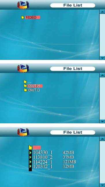
Playback
When there is new recorded file, the indication LED NEW below the LCD screen will be on, and the
indication icon on the LCD screen appears and flashes.
Follow the steps to play the recorded files.
1). In viewing mode, press the Enter button on the remote
control or the joystick on the receiver to enter the operation
interface.
2). Select the folder VIDEO and press Enter. You will see some
folders name by date. For example: 080101 means the videos in
this folder are recorded on January 1st, 2008.
3). Select a folder and press Enter to enter submenu. You will
see the recorded files named by time. For example: 101024_1
means the video is recorded at 10:10:24 and from camera 1.
4). Select the video you want to view and press Enter button,
the video will be played on the LCD screen. Then you can use
the navigation buttons to play/pause, stop, forward, backward.
9
Accessing Menu System
The functions of the Menu button and navigation buttons/Enter button on the remote control are the
same as the joystick and Menu button on the back of receiver. In this section we take the remote control
as example to show the menu operation.
Press the Menu button on the remote control to enter menu system. Use the navigating buttons to
navigate up/down/left/right in the menu, and press the Enter button to confirm a setting or selection.
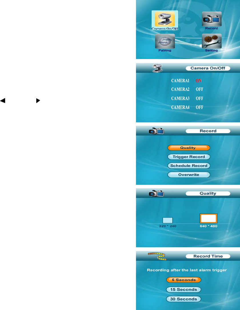
Main Menu
The Main Menu contains 4 submenus:
1. Camera On/Off – Use the menu to switch on or switch off a
specified camera.
2. Record – Use the menu for SD card recording settings.
3. Pairing – Use the menu to add camera(s) to the receiver.
4. Setting – Use the menu for system settings, such as alarm
volume, brightness and date & time setting.
Camera On/Off Menu
Select a camera by pressing the UP ▲or DOWN ▼ button, then
pressing LEFT or RIGHT button to switch on or switch off
the camera. Press Enter button to confirm the change and exit.
Record Menu
You can set up the recording parameters in record menu.
Note: To use the recording function, make sure a SD card is
inserted into the SD card slot. When there is new video recorded,
the indication LED NEW below the LCD screen will be on, and
when the SD card is full of memory, the indication LED FULL will
be on.
- Quality: The resolution of recorded videos. There are two
options: 320 x 240 pixels and 640 x 480 pixels.
Record videos are much clearer in 640 x 480 pixels mode but
more fluent in 320 x 240 pixels mode.
- Trigger Record: The recording time when there is motion
detected by a camera in automatic recording mode. The
recording time can be set to 5s, 15s or 30s.
10
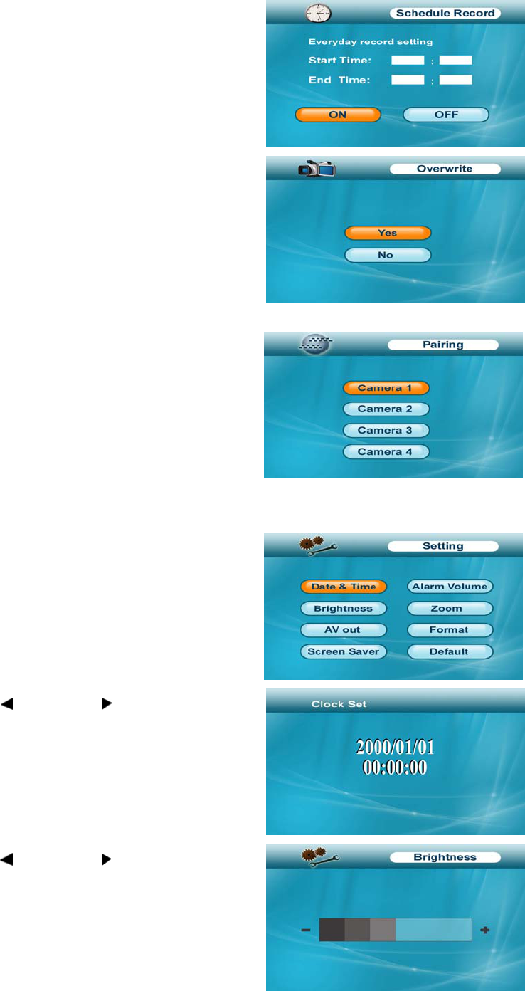
- Schedule Record: Set the schedule recording time for each
day. Time can be set from 00:00 to 23:59. Then select the menu
ON to enable schedule recording.
- Overwrite: Decide whether to cover the initial recorded files
when SD card is full of memory.
Pairing Menu
The system comes with camera(s) that have already been
paired. The pairing function assigns each camera to a different
channel on the wireless receiver (up to 4 cameras), and is
necessary for configuring additional cameras.
Use the UP ▲or DOWN▼ button to select the desired pairing
channel, and press the Enter button to begin the pairing
process with a camera.
NOTE: It is highly recommended to pair the cameras to the receiver before permanently mounting the
cameras. See the pairing section of this manual for details.
Setting Menu
The Setting menu contains 8 submenus:
- Date & Time: Use LEFT and RIGHT buttons to select the
item, and use UP ▲ and DOWN▼ buttons to set the time.
- Brightness: The Brightness Menu is used to adjust the
brightness. Use the LEFT and RIGHT buttons to change
the bar from DARKEST (left) to LIGHTEST (right). Press Enter
button to confirm the adjustment.
11
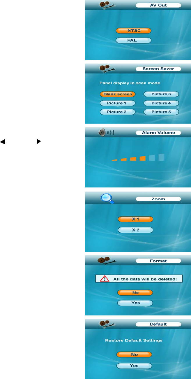
- AV Out: Select the TV system when outputting the video/audio
to TV, DVR/VCR or other viewing/recording devices.
- Screen Saver: 5 pictures are stored in the system. You can
select one picture to make it be shown on the LCD screen in
scan mode. Or you can select Blank screen to make the LCD
screen display nothing in scan mode.
- Alarm Volume: Receiver beeps to alert you when motion
detected by camera. Press LEFT or RIGHT button to
increase or decrease the volume of the audio alarm.
- Zoom: The image can be set at original size or double size by
selecting zoom x1 and zoom x 2. In double size mode, press the
navigation buttons to view the parts out of the LCD screen.
- Format: Select Yes to format the SD card. After formatting, all
the data stored in the SD card will be deleted.
Note: Be cautious to use this function.
- Default: Select Yes to reset the receiver to factory defaults –
all menu settings will be reset.
12
Camera Pairing
The system comes with camera(s) that have already been paired. These cameras will communicate with
the receiver once powered on.
The pairing function assigns each camera to a different channel on the wireless receiver (up to 4
cameras), and is necessary for configuring additional cameras.
NOTE: It is highly recommended to pair the cameras to the receiver before permanently mounting the
cameras.
1. Power on the receiver by connecting it to power outlet with supplied 5V power adaptor.
2. Power on the camera by connecting it to power outlet with supplied 9V power adaptor.
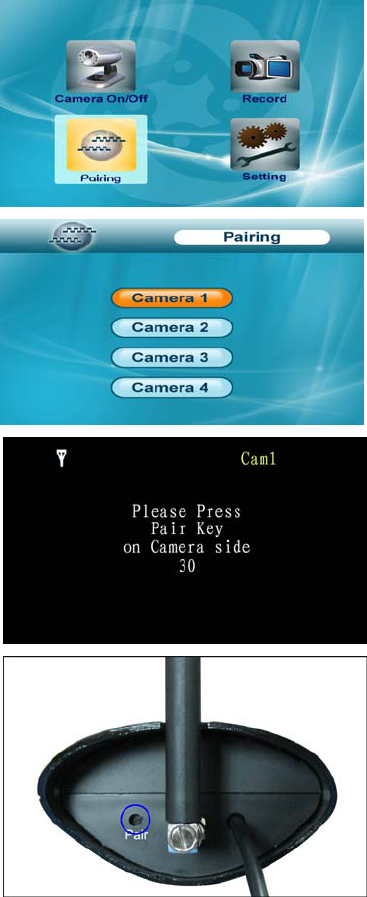
3. Press the Menu button on the receiver or remote controller.
Navigate to the Pairing menu option by pressing the ▼▲◄►
buttons on the remote controller or operating the joystick on the
receiver. Press Enter button to enter the pairing operation.
4. Select a channel by pressing the UP and DOWN ▼▲ buttons
on the remote controller or pushing upwards/downwards the
joystick on the receiver. Press Enter button to confirm the
selection.
5. A message will be displayed on the receiver screen.
The receiver will count down from 30~0 – you must press the
Pair button on the camera during this time to successfully pair
the camera.
If the button on the camera is not pressed, the receiver will
return to the view screen, and no pairing will take place.
6. Press the Pair button on the back of the camera.
Once the camera has been paired, it will be immediately
viewable on the receiver monitor.

13
Troubleshooting
If you have problems with the system, there is often a quick and simple solution. Please try the following:
Problem Solution
No picture from a camera
1. Check all connections to the camera. Make sure the adaptor is
plugged in.
2. Make sure that the receiver is ON.
3. Make sure that the camera is in range of the receiver.
The picture is dropping
1. Move the camera closer to the receiver.
2. Try repositioning the camera, receiver or both to improve the
reception.
Audio problems
1. Increase the volume when there is no sound.
2. Make sure that there is sound within range of the camera
microphone.
3. If the unit emits a loud screeching noise (audio feedback), move
the camera or receiver farther apart.
The picture is or has become
choppy
The picture may become choppy when experiencing a lower frame
rate (i.e. 10 frames per second vs. a higher 20 frames per second).
Try moving the camera closer to the receiver. Remove obstructions
between the receiver and camera.
The Picture appears to be grainy
when using AV out function to
view on a large screen TV/Monitor
The purpose of the AV output is for convenience only. When using
with large screen TV/Monitor, the picture might be grainy as the
camera limits video resolution to VGA (640x480 pixels). This is not a
product defect.
1. For best performance use with TV/Monitor PIP (Picture in Picture)
function. Check your TV/Monitor product manual to see if this feature
is available on your TV/Monitor.
2. View video on a smaller screen TV/Monitor.
Recording Problems
1. Make sure the SD card is inserted to SD card slot correctly.
2. Check the SD card is not full of memory.
3. Make sure the size of SD card is compatible with the system. The
system can support up to 16GB SD card.
14
Appendix #1 – System General Specifications
Operating Frequency Range 2.400GHz~2.483GHz
TX Power 14dBm
RX Sensitivity -81dBm
Type of Spread Spectrum Used FHSS
Type of Modulation Used GFSK
Data Rate 2Mbps
Communication Range 100m Line in Sight
Appendix #2 - Receiver Specifications
Display Size/Type 7” TFT LCD
Resolution H: 480 RGB, V: 234
Viewing Angle H: 145 degree, V: 115 degree
A/V Output Resolution/ Frame Rate VGA/ QVGA Selectable
Power Requirement 5.0Vdc +/-10%
Power Consumption 850mA Max
Operating Temp Range -10~50 degree C
Operating Humidity Range Within 85%RH
Dimension 176mm x 40mm x 150mm
Regulation Compliance FCC/ CE
RoHS Compliance Yes
Housing Material ABS Plastic
Appendix #3 - Camera Specifications
Camera(s)
Image Sensor Type 1/4" Color CMOS Image Sensor
Effective Pixel H: 640, V: X: 480,
Image Resolution H: 640, V: 480 @ 9fps. H:320, V: 240 @25fps
Lens 4.5mm F 2.0
AGC Auto
AES Speed 1/60~1/15,000 Sec
White Balance Auto
Power Requirement 9V DC +/-10%.
Power Consumption Max 350mA with IR LED, Max 145mA without IR LED.

15
Operating Temp Range -10~50 degree C
Operating Humidity Range Within 85%RH
Dimension 175mm x 156mm x 32mm
Environment Rating IP56
Regulation Compliance FCC
RoHS Compliance Yes
Camera Housing Material Aluminum
Note:
The antenna(s) used for this transmitter must be installed to provide a separation distance of at least 20 cm
from all persons and must not be co-located or operating in conjunction with any other antenna or transmitter.
FCC NOTE:
This device complies with Part 15 of the FCC Rules.
Operation is subject to the following two conditions: (1) this device may not cause harmful interference, and (2)
this device must accept any interference received, including interference that may cause undesired operation.
THE MANUFACTURER IS NOT RESPONSIBLE FOR ANY RADIO OR TV INTERFERENCE CAUSED BY
UNAUTHORIZED MODIFICATIONS TO THIS EQUIPMENT. SUCH MODIFICATIONS COULD VOID THE
USER’S AUTHORITY TO OPERATE THE EQUIPMENT.
IC NOTE:
Operation is subject to the following two conditions: (1) this device may not cause harmful interference,and (2)
this device must accept any interference, including interference that may cause undesired operation of the
device."