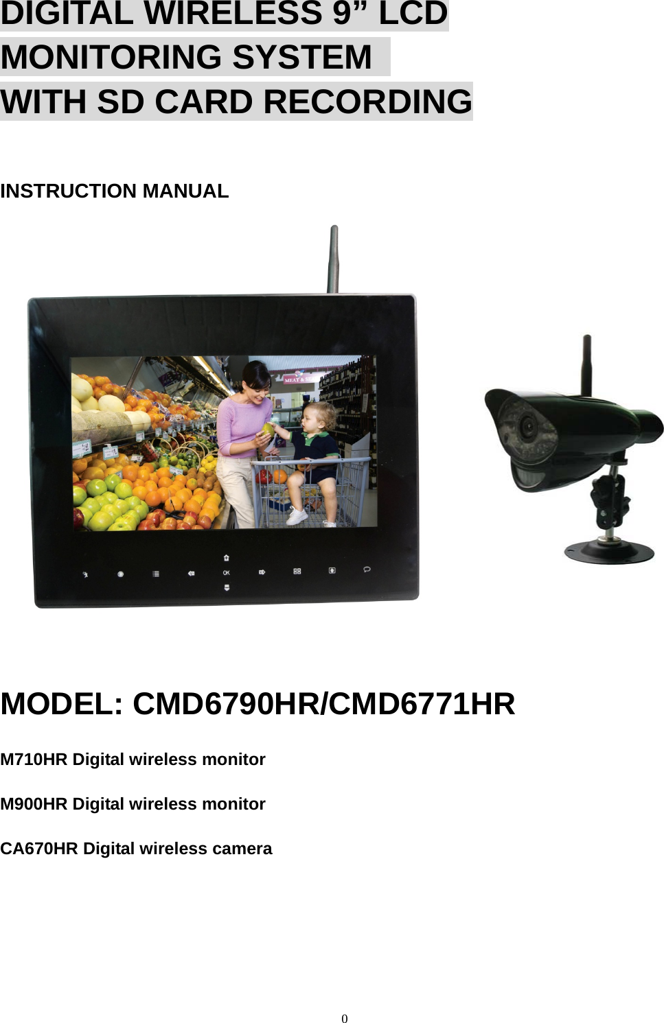
RDI Technology M900HR DIGITAL WIRELESS MONITOR User Manual CMD6771HR

RDI Technology (Shenzhen) Co., Ltd. DIGITAL WIRELESS MONITOR CMD6771HR

User Manual

0  DIGITAL WIRELESS 9” LCD MONITORING SYSTEM   WITH SD CARD RECORDING INSTRUCTION MANUAL        MODEL: CMD6790HR/CMD6771HR M710HR Digital wireless monitor M900HR Digital wireless monitor CA670HR Digital wireless camera
 1 Camera Features • VGA resolution camera • Night vision allows for low light viewing up to 40 feet / 12 meters  ③ • Built-in microphone • Weatherproof for outdoor use • PIR Sensor for motion detection ③ IR illumination range of 40ft./12m under ideal conditions. Objects at or beyond this range may be partially or completely obscured, depending on the camera application. Receiver Features • RF Chip: Nordic 24L01 • Sensor: MI-360 1/4 Cmos sensor • 850nm IR Led visible distance up to 10m • 9’’ Hannstar TFT Lcd Digital panel (800 RGB  ×480) • Two way audio   • Scan function     • PIR trigger or Video motion detect recording   • Manual recording   • Touch button operation     • Schedule recording separate settings from Monday to Sunday     • Manual and PIR trigger or Video motion detect recording is available in Quad mode     • SD Card capacity up to 32GB     • One Lcd monitor can pair four cameras     • Frame rate: 12 fps @640×480 max/20 fps @320×240 max     • RF range: 150 meter (Line of sight)     • New recording indicator     • Memory card full indicator   • Quad feature     • PIP ( Picture in picture in play back mode)     • PIR trigger and Video motion detect alert     • USB output for webcam function (Skype, MSN)     • Firmware upgrade by USB port or SD card
 2    Getting Started The system comes with the following components:                                        Check your package to confirm that you have received the complete system, including all components shown above. Wireless Receiver Front Controls 1. LCD Screen – Displays video from the camera(s) or displays system operations. 2. TOUCH KEYs :    Motion: Touch    to enter auto recording mode. Receiver starts to record when there is motion detection in camera side.     Record: Touch    and receiver start to record manually.                      In Recoding mode, the only touch key    that work are “ Record” and “Talk” . Touch again to stop recording and exit record mode.
 3 Menu: Touch    to access the receiver menu. Press the key again to exit.  OK: In “Menu” mode, Press    to perform “confirmation” operation; in viewing mode, press   to enter file list- Playback function.    Volume down/up : In “Menu” mode, work as direction key left/ right; In “Zoom  ×2”, they can move the image to left or right; In “Preview” mode, it can change volume of the LCD.  Channel down/up: In “Menu” mode, work as direction key up/down; In “Zoom  ×2”, they can move the image upward or downward; In “Preview” mode, it can change channel between different cameras.  View: In manual channel switch mode, press   to enter auto channel switch mode, LCD will automatically switch to next channel connected to working camera; in auto channel switch mode, touch to enter “Quad view”; In “Quad view”, touch to enter auto channel switch mode; In “playback” mode, playing recorded videos, press the key to open a small window to monitor the live image took by current camera. Scan: Touch    and the receiver is in scan mode (screen saving). When receives signals from the PIR trigger or Sound trigger, the LCD will lighten up and show the images from the camera. Talk: Touch and hold    to talk back to the camera whose image is displayed on the screen.  3. Indication LEDs – Indicates the status of the system. There are 4 indication LEDs: NEW: Indicates new recorded video.  FULL: Indicates that the SD card is full of memory. It is only available when Overwrite is disabled. MOTION: Indicates that the receiver is in auto recording mode. Receiver starts to record when there is motion detection in camera side. SCAN: Indicates that the receiver is in scan mode (screen saving)                                                                   Back Controls 4. Receiver Antenna – receives & sends signals from or to the camera(s). Adjust the antenna to vertical position when the signal reception is not good. 5. Speaker – Produces the sound transmitted from the camera(s). 6. Hanging Hole – Insert the screw which is already installed on a wall into the hole, and push the receiver downwards to hang the receiver on the wall.
 47. Wall Mounting Hole – Screw the wall mounting bracket to the hole, then fix the bracket to the wall to mount the receiver on the wall. 8. Zoom Button – In “×1” mode, press to enter “×2” mode,  ×2 shows on the screen; In “×2” mode, press to enter “×1” mode,  ×2 doesn’t show on the screen. 9. Joystick – A. Navigation button (▲▼◄► arrows): servicing button, can control direction of Pan/Tilt cameras.    B. Enter/Del button: servicing button, used for upgrading software; when enter File list, pick a recorded file and press Del to delete the video. Before the file is completely deleted, you can see a warning Del xx? You can choose to delete the file or keep it.   10. A/V – Press it to enter A/V Out mode and press again to back to Lcd mode; if the Lcd is powered off in A/V Out mode, it stays A/V Out mode when power on again. 11. Power Switch– Slide the switch to ON or OFF position to switch on/off the receiver. 12. Microphone– Receives sounds from the area near the receiver and transmits sound from the receiver to the camera (only when TALK is pressed down and held) 13. DC 5V Power Input – Connect   the included DC 5V power adaptor  to power the receiver.                 14. SD Card Slot – Insert SD card to this SD card slot for both       video and4 audio recording.         15. USB Port: Used webcam            function5 (Skype, MSN) and for firmware upgrade                         16.A/V Out Port – Connect the included A/V cable to view video from the receiver on a TV or monitor, or record to a VCR/DVR.                                   17. Receiver Stand – Enables the receiver to stand on a flat surface, such as a table or countertop. You can also adjust the viewing angle by rotating the stand. Wireless Receiver Installation The LCD Receiver can be setup for use on a tabletop, or mounted to a wall or underneath a counter or cupboard. 1. Before receiver installation, choose one installation method from below 3 methods: 1). Desktop or table stand. For this method, you only need to place the receiver on a desktop and use the supplied receiver stand. 2). Hung on the screw which is fixed on a wall. Decide where to hang the receiver first. Make sure the range between the position and the nearest power output port is no more than 5 feet. Drill a hole on the wall where you decide to hang the receiver, insert one plastic anchor and fix a screw into the plastic anchor. Now the receiver can be hung on the screw (receiver back control number  ⑤). 3). Wall mounting Decide where to install the receiver first. Make sure the range between the position and the nearest power output port is no more than 5 feet. Screw supplied wall mounting bracket to the receiver (receiver back control number ⑥), then drill 3 holes on the wall where you decide to install the receiver, then insert 3 plastic anchors and fix the wall mounting bracket to the anchors with supplied screws.
 52. After the receiver is well positioned, plug the AC adaptor power output cable into the 5V POWER input of the receiver, and plug the power plug into a wall outlet or surge protector. 3. If you wish to view the receiver images on a larger screen, connect one end of the included AV cable to the AV output of receiver, and connect the other end to the Video IN (Yellow) and Audio IN (White) ports on the TV, VCR or other viewing/recording devices. Note: When outputting Audio/Video to TV, etc, press the AV button on the remote control to output audio and video to TV. The receiver installation is now completed.  Wireless Camera Front & Side Controls 1. Camera Antenna – Sends & receives signals to or from the receiver.  2. AC Adaptor Jack – Plug the AC adaptor to the jack for camera’s power supply. 3. Wall Mounting Bracket – Use the bracket to mount the camera on a wall or other flat surfaces. 4. IR LEDs – Infrared LEDs provide viewing in no/low light conditions  5. Lens – Catches the video in front of the lens and transmits video from camera to receiver.     6. Microphone – Receives sounds from the area near the camera, and transmits sound from the camera to the receiver. 7. PIR Sensor – Detects motion in front of the lens and emits detection signal to transmitter. 8. Speaker – Produces the sound transmitted from the receiver. Back Controls 9. Pair Button – The pair button is located on the back of the camera, it is used to pair the camera with receiver. 10. Bracket Jack – Screw the wall mounting bracket to the jack, and fix the bracket on a wall or other flat surfaces.
 6Camera Installation Before you install the camera, carefully plan where and how it will be positioned, and where you will route the cable that connects the camera to the power adaptor. Before starting permanent installation, verify its performance by observing the image on the receiver when camera is positioned in the same location/position where it will be permanently installed and the receiver is placed in the location where it will be used most of the time. Installation Warnings Aim the camera(s) to best optimize the viewing area: Select a location for the camera that provides a clear view of the area you want to receive, which is free from dust, and is not in line-of-sight to a strong light source or direct sunlight. Avoid installing the cameras where there are thick walls, or obstructions between the cameras and the receiver. Night Vision This camera has built-in IR LEDs, which provides the camera with the ability to view images in no/low light conditions. Night vision will be automatically switched on in low illumination condition. Installing the Camera 1. Carefully unpack the camera. NOTE: If you are installing cameras that did not come with the system, please see the pairing camera section of this manual for installation details.      2. Mount the camera to the wall. Mark the position of the screw holes on the wall, drill holes and insert the supplied 3 plastic anchors, then firmly fix the camera bracket to the plastic anchors with supplied screws. 3. Adjust the viewing angle of the camera You can adjust the viewing angle to monitor desired area by rotating the camera bracket. 4. Connect camera power After the camera is installed, plug the AC adaptor power output cable into the 9V POWER jack of the camera, and plug the power plug into a wall outlet or surge protector. NOTE: You can install additional cameras (maximum of 4 cameras). When adding cameras that were not included in the original box, you will need to pair the cameras with the receiver. Refer to the camera pairing section of this manual. Camera installation is now completed.
 7Viewing Mode 1. Signal Indicator – The signal indicator shows the strength of the signal being received from the camera. one or no bars indicate a poor signal and 4 bars indicate a strong signal. Signal Indicators:   2. Channel Indicator–Displays the current channel number. Use touch key    to switch between available cameras. Note: To automatically switch between channels, use touch key   View. In auto switch mode, touch   View to enter quad mode.   3. New Record Indicator – When there is new recorded file, the indicator will be shown on the LCD screen and flashes to alert users. Meanwhile, the indication LED NEW below the LCD screen will be on. Flashes yellow when writing data to the SD card. Flashes red when the SD card is full. 4. SD Card Indicator – When a SD card is inserted into the SD card slot, the indicator will be shown on the LCD screen. 5. Recording Indicator–When the receiver is recording, the red indicator  ●REC will be shown on the LCD screen. And under the indicator, you can see the name of the recorded file. OUT OF RANGE Warning When the receiver can’t get signal from cameras, warning message will be displayed. Reposition the camera, or check the camera power connection.   To change viewing modes: 1. Use   View to enable Auto Sequence Viewing Mode and switch automatically between channels. 2. Use    to switch channels manually.   NOTE: By default, Auto Sequence Viewing Mode is enabled when you first power on the system, and when you exit Screen Saver mode.
 8Quad Mode   Use Quad mode to view up to four cameras simultaneously. Users can set schedule recording in quad mode.   SD Card Recording The system is designed for SD card recording. You can manually record the video at your desire or the receiver records when there is motion detected by the cameras and under the A/REC function. Before recording, you need to insert a SD card to the SD card slot. The system can support the size of up to 32GB SD card.  Recording Mode Auto Recording Use  Motion to set the system to automatic recording mode. In this mode the receiver starts recording when motion detected by any activated camera. The recording time can be set to 5s,15s or 30s after last detection.   In quad mode, when motion is detected by a camera, the receiver switched to display the image from the camera in full screen status and starts recording when you set the mode of QUAD is Single. After recording, it automatically switches back to quad mode. But when you set the mode of Trigger Recording is Quad,the receiver switched to display the image from the camera in quad screen status and starts recording. Press  Motion again to cancel automatic recording mode. Manual Recording Press   Record, the receiver starts recording. Press the key again to cancel manual recording. Schedule Recording Set the recording start time and end time, then switch on schedule recording in the menu to enable schedule recording. In this mode the receiver records at a certain time every day. Playback When there is new recorded file, the indication LED NEW below the LCD screen will be on, and the indication icon on the LCD screen appears and flashes. Follow the steps to play the recorded files. 1). In viewing mode, press the OK on the receiver to enter the operation interface, show two submenus, VIDEO and PHOTO. Under the PHOTO menu contain FAMILY, FRIENDS, PERSONAL (when insert the SD card, this files of name can’t be deleted or renamed.), which can store the pictures.
 92). Select the folder VIDEO and press OK. You will see some folders name by date. For example: 20120520 means the videos in this folder are recorded on May 20th, 2012.   3). Select a folder and press OK to enter submenu. You will see the recorded files named by time. For example: 1-155937 means the video is recorded at 15:59:37 and from camera 1.When under the mode of QUAD,the recorded files named by Q-hour/minter/second . 4). Select the video you want to view and press OK, the video will be played on the LCD screen. Then you can use the navigation buttons to play/pause, stop, forward, backward. When you played the video , press   View, you can see a small window on the top left corner of the screen to show the picture of CAMERA1, switch other channel by  ,re-press    View can close this function.    Accessing Menu System Use  Menu Menu on the receiver to access to Menu system. Use     to navigate up/down/left/right in the menu, and press the OK to confirm a setting or selection. Main Menu The Main Menu contains 6 submenus: 1.Settings –Use the menu for system settings, such as alarm volume, brightness and date & time setting. 2. Camera On/Off – Use the menu to switch on or switch off a specified camera. 3. Brightness – Use the menu for adjust the brightness of the screen. Use    to change the bar from DARKEST (left) to LIGHTEST (right). Press OK to confirm the adjustment. 4. Video motion detect – Use the menu to set Camera’s motion detect sensitivity and mask area. 5. Recording–Use the menu for SD card recording settings.
 106.Pairing –Use the menu to add camera(s) to the receiver. Settings Menu The Settings menu contains 8 submenus:  - Date & Time: Use    to select the item, and use     to set the time.   - AV Out: Select the TV system when outputting the video/audio to TV, DVR/VCR or other viewing/recording devices.     - Screen Saver: Lcd set into the black screen display or the Photo Frame.(system set the black screen). Use the Screen Saver to conceal the fact that the LCD receiver is actually a surveillance recorder. The system set the black screen that let the LCD receiver simulate a picture frame. When motion is detected by a camera, the LCD receiver will display the triggered camera in single channel full-screen.   If you set the Photo Frame function (under the photo frame menu with Interval and Transition options, can switch time and effect for picture.), when you press the Scan/Del button on the remote activate Screen Saver Mode. The pictures which store on the SD card will appear on the LCD receiver and "SCAN" will light up on the bottom of the LCD receiver.Press the Scan/Del
 11button on the remote again to disable Screen Saver.  NOTE:If you directly store the pictures on the SD card from the computer, the LCD monitor can’t accurately identify it. Right operation: press  Talk when you use a USB cable to connect the LCD with the computer, after inserting the USB, loosen  Talk, so you can see a program named PHOTORUN.EXE, double click it then you can upload the pictures to SD card, and this pictures will be accurately read. - Format: Select Yes to format the SD card. After formatting, all the data stored in the SD card will be deleted. Note: Be cautious to use this function.  - Alarm Volume: Receiver beeps to alert you when motion detected by camera. Press /  to increase or decrease the volume of the audio alarm. -Auto Mute: Auto Mute is a feature where you can choose the sound activated option. Using the sound activated mode, you will hear the sound when there is a certain level of sound.   Windows default is OFF. and you can continuously hear the sound from the side of camera.                                     when you set it ON, if the level of sound is below the level of sound activated and    last for 5 minutes, it is mute, you won’t hear any background sound. when the sound above this level, you can hear this sound. so only the sound must above the sound activated, you can hear the background sound, otherwise it is mute.
 12- Zoom: The image can be set at original size or double size by selecting zoom x1 and zoom x 2. In double size mode, press the navigation buttons to view the parts out of the LCD screen. - Default settings: Select Yes to reset the receiver to factory defaults.   Camera On/Off Menu Select a camera by pressing  , then pressing  / to switch on or switch off the camera. Press     to confirm the change and exit.   NOTE: The currently selected camera will have On/Off highlighted in RED.Any disabled channels will beblacked out in Quad mode.  Brightness The brightness of the screen can be adjusted with the    / .The     makes the screen lighter and the  makes the screen darker.  Video motion detect The option of this key can separately set the camera’s sensitivity of motion detect and mask area. You can use the Mask Area menu to set the area where you don’t want to motion detect ,and the remaining of area ,if there is abnormity, the corresponding camera will trigger the monitor to record it.
 13Recording Menu Use the Record menu to change image quality, motion recording time, set a recording schedule, and enable/disable overwrite. You can set up the recording parameters in record menu. Note: To use the recording function, make sure a SD card is inserted into the SD card slot. When there is new video recorded, the indication LED NEW on the LCD screen will be on, and when the SD card is full of memory, the indication LED FULL will be on. - Quality: The resolution of recorded videos. There are two options: 320 x 240 pixels and 640 x 480 pixels. Record videos are much clearer in 640 x 480 pixels mode but more fluent in 320 x 240 pixels mode. - Trigger Recording: The recording time when there is motion detected by a camera in automatic recording mode. The recording time can be set to 5s, 15s or 30s。  - Schedule Recording: Set the schedule recording time for each day. Time can be set from 00:00 to 23:59. Then select the menu ON to enable schedule recording.    - Overwrite: Decide whether to cover the initial recorded files when SD card is full of memory.
 14 Pairing Menu The system comes with camera(s) that have already been paired. The pairing function assigns each camera to a different channel on the wireless receiver (up to 4 cameras), and is necessary for configuring additional cameras. Use    to select the desired pairing channel, and press OK to begin the pairing process with a camera. NOTE: It is highly recommended to pair the cameras to the receiver before permanently mounting the cameras. See the pairing section of this manual for details. Camera Pairing The system comes with camera(s) that have already been paired. These cameras will communicate with the receiver once powered on. The pairing function assigns each camera to a different channel on the wireless receiver (up to 4 cameras), and is necessary for configuring additional cameras. NOTE: It is highly recommended to pair the cameras to the receiver before permanently mounting the cameras. 1. Power on the receiver by connecting it to power outlet with supplied 5V power adaptor. 2. Power on the camera by connecting it to power outlet with supplied 9V power adaptor. 3. Press the  Menu the receiver. Navigate to the Pairing menu option by pressing the   /  on the receiver. Press OK to enter the pairing operation. 4. Select a channel and press OK to confirm the selection. 5. A message will be displayed on the receiver screen. The receiver will count down from 30~0 – you must press the Pair button on the camera during this time to successfully pair the camera. If the button on the camera is not pressed, the receiver will return to the view screen, and no pairing will take place.
 156. Press the Pair button on the back of the camera. Once the camera has been paired, it will be immediately viewable on the receiver monitor.
 16Troubleshooting If you have problems with the system, there is often a quick and simple solution. Please try the following: Problem Solution No picture from a camera 1. Check all connections to the camera. Make sure the adaptor is plugged in. 2. Make sure that the receiver is ON. 3. Make sure that the camera is in range of the receiver. The picture is dropping 1. Move the camera closer to the receiver. 2. Try repositioning the camera, receiver or both to improve the reception. Audio problems 1. Increase the volume when there is no sound. 2. Make sure that there is sound within range of the camera microphone. 3. If the unit emits a loud screeching noise (audio feedback), move the camera or receiver farther apart. The picture is or has become choppy The picture may become choppy when experiencing a lower frame rate (i.e. 10 frames per second vs. a higher 20 frames per second).Try moving the camera closer to the receiver. Remove obstructions between the receiver and camera. The Picture appears to be grainy when using AV out function to   view on a large screen TV/Monitor The purpose of the AV output is for convenience only. When using with large screen TV/Monitor, the picture might be grainy as the camera limits video resolution to VGA (640x480 pixels). This is not a product defect. 1. For best performance use with TV/Monitor PIP (Picture in Picture) function. Check your TV/Monitor product manual to see if this featureis available on your TV/Monitor. 2. View video on a smaller screen TV/Monitor. Recording Problems 1. Make sure the SD card is inserted to SD card slot correctly. 2. Check the SD card is not full of memory. 3. Make sure the size of SD card is compatible with the system. The system can support up to 16GB SD card.
 17 System General Specifications Operating Frequency Range  2.400GHz~2.483GHz TX Power  14dBm   RX Sensitivity  -81dBm Type of Spread Spectrum Used  FHSS Type of Modulation Used  GFSK Data Rate  2Mbps Communication Range  150m Line of Sight  Electrical Parameter:  Camera(s) Transmit Frequency Range 2400Mhz~2483.5Mhz Data Rate  2 Mbps Transmitting Power  16dBm (TYP) Modulation Type  GFSK with FHSS Transmitting Distance  150m (Line of Sight) Image Sensor Type  1/4” Color CMOS Image Sensor Effective Pixels  H: 640    V: 480 Image Processing  Motion JPEG Image Resolution / Frame Rate  H: 640    V: 480 / 30 fps Max Lens  4.5mm / F1.9 (ICR cut Filter) Viewing Angle (Diagonal)  64° (FOV) Minimum Illumination  <5 Lux (IR On), >30 Lux IR Off IR LED / Night Vision Range  16 Leds / 850nm, 10m (with IR Led) Power Requirement  9V DC 600mA ±5%
 18Power Consumption 460mA Max (with IR On and talk back) 185mA Max (with IR Off    / without talk back) Operating Temperature  14°F ~ 104°F (-10°C ~ 40°C) Operating Humidity  0% ~ 85%      Lcd monitor Receiving Frequency Range 2400Mhz~2483.5Mhz Data Rate  2 Mbps Receiving Sensitivity    -81dBm Modulation Type  GFSK with FHSS Lcd Panel size  9 Inch Lcd Resolution  800 RGB (H) x 480 (V) View Angle  H: 140°    V: 110° A/V Out Resolution  VGA 640x320 / 10 fps,QVGA 320x240 / 20fps Power Requirement  5V DC 2A ±5% Power Consumption  950mA Max Operating Temperature  14°F ~ 104°F (-10°C ~ 40°C) Operating Humidity  0% ~ 85%  This device complies with Part 15 of the FCC Rules. Operation is subject to the following two conditions: (1) this device may not cause harmful interference, and (2) this device must accept any interference received, including interference that may cause undesired operation.
 19FCC NOTICE: This device complies with Part 15 of the FCC Rules. Operation is subject to the following two conditions: (1) this device may not cause harmful interference, and (2) this device must accept any interference received, including interference that may cause undesired operation.    NOTE: This equipment has been tested and found to comply with the limits for a Class B digital device, pursuant to part 15 of the FCC Rules.   These limits are designed to provide reasonable protection against harmful interference in a residential installation.   This equipment generates, uses and can radiate radio frequency energy and, if not installed and used in accordance with the instructions, may cause harmful interference to radio communications.   However, there is no guarantee that interference will not occur in a particular installation.   If this equipment does cause harmful interference to radio or television reception, which can be determined by turning the equipment off and on, the user is encouraged to try to correct the interference by one or more of the following measures: - Reorient or relocate the receiving antenna. - Increase the separation between the equipment and receiver. -Connect the equipment into an outlet on a circuit different from that to which the receiver is connected. -Consult the dealer or an experienced radio/TV technician for help. The antenna used for this transmitter must be installed to provide a separation distance of at least 20 cm from all persons and must not be co-located or operated in conjunction with any other antenna or transmitter. IC NOTE: This device complies with Industry Canada licence-exempt RSS standard(s). Operation is subject to the following two conditions: (1) this device may not cause interference, and (2) this device must accept any interference, including interference that may cause undesired operation of the device.  Le présent appareil est conforme aux CNR d'Industrie Canada applicables aux appareils radio exempts de licence. L'exploitation est autorisée aux deux conditions suivantes : (1) l'appareil ne doit pas produire de brouillage, et (2) l'utilisateur de l'appareil doit accepter tout brouillage radioélectrique subi, même si le brouillage est susceptible d'en compromettre le fonctionnement.

Navigation menu