RDI Technology RX200 WIRELESS RECEIVER User Manual USERS MANUAL
RDI Technology (Shenzhen) Co., Ltd. WIRELESS RECEIVER USERS MANUAL
USERS MANUAL
900MHz Wireless Receiver system
Congratulations on your purchase of the 900 MHz Wireless Receiver Systems
(WRS45234). WRS45234 consists of a wireless receiver and a wireless color Camera,
The WRS45234 Wireless receiver surveillance system is an ideal combination for
monitoring the porch, watching the yard, pool, pets or the baby. It is also suited to many
small businesses.
.
FEATURES
• 900MHz wireless technology
• Antenna orientations is adjustable
• Both audio and video output
• Two channels selection for cameras
• Supports up to 2 cameras
• Manual or auto switching between cameras
• Adjustable cycle time between different channels
• Sound and light indication in alarm state
• Alarm sound ON/OFF selection
• Adjustable alarm sensitivity
• Channel lock
• AC power adaptor or battery(not includes) operation.
SYSTEM CONTENTS
•RX200-900 wireless receiver x1
•CA330 wireless color camera x1
•Power adaptor x2
•Adaptor cable x1
•Hardware kit x1
•Manual x1
THINGS TO CONSIDER BEFORE INSTALLATION
For best performance, follow these simple guidelines:
• Camera(s) should be installed between 8 and 13 feet above the area to be monitored
• The Camera should be aimed accordingly to optimize viewing area
• For best transmission, avoid installations where there are thick walls or major
obstructions between the Camera and Receiver
INSTALLING THE CAMERA (TRANSMITTER)
1. Unpack the Camera.
2. Decide whether the Camera will be wall-mounted or sit on a desk/table top. If wall
mounting there is a useful drilling guide on the back cover of these instructions. Use the
hardware kit in the package to fix the camera. The Camera can be adjusted for either
mounting scenario by rotating the Camera to the required position.
3. Decide whether to connect using AC power or battery. If using battery install the 9V
LI-polymer special battery to the camera. If using the 9V camera power adapter, just
connect power jack. Make sure the Camera is positioned no more than 5 1/2 feet from an
AC power outlet.
4. Select the Camera operating channel under the housing of the camera by moving the
slide switch to position 1 or 2. Switch is preset to channel 1
.
The Camera (Transmitter) installation is now complete.
SETTING UP THE RECEIVER
1. Connect one end of the cable (RCA <male>) to the rear of the receiver, another end
(RCA cord) to your television's A/V inputs, the yellow plug to the VIDEO IN jack and the
white plug to the AUDIO IN jack.
2. Plug the receiver power adapter into the 9V DC power jack on the back of the receiver
and plug the power adapter into any 120 V/240 V power outlet.
3. Place the receiver either on top or near to your TV. Rotate the antenna to a vertical
position.
OPTIMIZING THE WIRELESS CAMERA SYSTEM
The 900MHz video signals pass easily through your home’s interior walls, but the signal
may be reflected by power wires or plumbing inside the wall. Usually a slight adjustment of
the Receiver and/or Camera antenna will improve reception. Take care not to force the
antennas past their lock positions.
The most common source of interference is microwave ovens and cell phones. Try to
avoid mounting the Receiver near a microwave oven or other source of RF interference
such as cordless phones.
MULTI-CAMERA OPERATION
This 900MHz wireless surveillance system is designed to work with up to 2 Cameras.
Additional Cameras (With different shapes for your option) are sold separately.
IMPORTANT: When using more than one Camera, make sure each camera is
assigned to a specific channel by adjusting the corresponding slide switch position.
Accordingly the slide switch located on the rear of the Receiver should be adjusted to
reflect the channels in use.
OPERATING THE SYSTEM
Set your TV to monitor the VIDEO INPUT designated for the Receiver.
The receiver can support up to two different camera/transmitter signals. You can switch
from one camera to the next either manually or automatically via button on the top panel of
the receiver.
MANUAL MODE
To select one of the two channels manually, press the MANUAL button on the top panel of
the receiver.
The red LED will light and the receiver will switch to a different channel (CAM1, CAM2)
each time when the MANUAL button is pressed. To avoid searching channels that do not
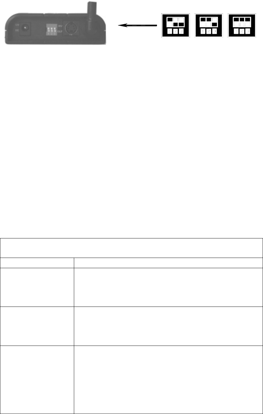
have cameras/transmitters assigned to them, set the slide switch (located on the rear
panel of the receiver) for those corresponding position. When you have selected a
channel with an active camera, that video will appear on your TV screen.
CAM1 IN USE CAM1 AND 2 IN USE ALL IN USE
AUTO MODE
To have the receiver automatically rotate through the channels, press the AUTO button on
the top panel of the receiver. The green LED will light and the receiver will continuously
scan through all channels which are ON. To avoid searching channels that do not have
cameras/transmitters assigned to them, set the slide switch for those corresponding
position. The monitor will display the picture from one camera to the next.
DWELL TIME SETTING
The dwell time (time taken to switch between cameras) is preset to 4 seconds and can be
adjusted between 2-30 seconds. To adjust the dwell time, press both the AUTO and
MANUAL button simultaneously. Each flash of the LED increases the dwell time by one
second. You can verify the time you setting by counting the flashing LED when you
released, one flash stand for 1 second.
ALARM SOUND SETTING
You can press the ON/OFF button on the front panel of the receiver to open/close the
alarm sound
ALARM SENSITIVITY SETTING
You can adjust the alarm sensitivity of the receiver by turning the alarm sensitivity adjust
knob at the rear of the receiver.
TROUBLE SHOOTING
If you are having trouble operating this product, please consult the guide below:
SYMPTOM REMEDIES
No camera picture
1. Check all connectors. Make sure camera(s) and receiver are
switched ON.
2. Ensure camera(s) and receiver are set to correct channel(s).
3. Make sure camera is within range of receiver.
Blank monitor
1. Make sure receiver is switched ON.
2. If using AC adapter, make sure it is plugged in.
3. If using batteries, make sure they are installed correctly, or
try replacing them.
Interference on
camera picture
1. Make sure each camera (transmitter) is within range, and
that no large obstructions are blocking the signal.
2. Try repositioning the camera, receiver or both to improve the
reception quality.
3. If a camera is positioned close to the receiver, point antenna
away from the receiver.
4. Reposition other nearby equipment transmitting on the 900

MHz frequency.
Audio problems
1. Ensure the volume is turned up sufficiently on the TV.
2. Make sure the sound is within the microphone range.
3. If the unit emits a loud wailing sound (feeds back), try
moving the camera away from the receiver or angle the
receiver differently.
SPECIFICATIONS
Camera
TV System PAL or NTSC
Integrated Lens 5.6mm, F2.0 fixed focus
Resolution 360 horizontal TV Lines
Signal/Noise Ratio 46 dB
High-Speed Electronic Shutter 1/60 - 1/15,000 sec
Image Sensor 1/4” CMOS
Min. Illumination 0.1 lux
Current Consumption 80~140mA
Overall Size 2.35”W x2.74Hx3.16D
Frequency Range 910 - 920 GHz
Modulation FM
Video Signal/Noise Ratio 46db
Audio Signal/Noise Ratio 45db
Channel Selection Electronic tuning
Case Finish UV resistant ABS plastic
Receiver/Monitor
Frequency Range 910 - 920 GHz
Signal/Noise Ratio 40dB
Operating Temperature -10oC to +40oC
Output Audio/Video
Humidity Less than 85%
Current Consumption Approx. 140 mA
Overall Size 3.8” L x 2.8” W x 0.6” H (Without antenna)
This device complies with part 15 of the FCC rules. Operation is subject to the following
two conditions: (1) this device may not cause harmful interference, and
(2) this device must accept any interference received, including interference
that may cause undesired operation.
FCC NOTE:
The manufacturer is not responsible for any radio or TV interference caused by
unauthorized modifications to this equipment. Such modifications could void the user's
authority to operate the equipment.
DRILLING
TEMPRATE
If you decide to mount the camera on a wall, use this page as a guide for
drilling the required holes