RDI Technology UDR777HD Guardian UDR777HD Wireless System User Manual UDR777HD
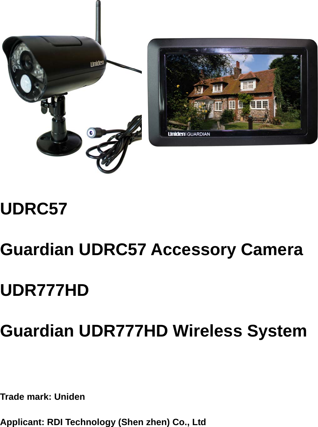
RDI Technology (Shenzhen) Co., Ltd. Guardian UDR777HD Wireless System UDR777HD
UserManual.wiki
>
RDI Technology
>
UDR777HD User Manual
Users Manual
Navigation menu
Upload a User Manual
Namespaces
Wiki Guide
HTML
PDF
Info
Views
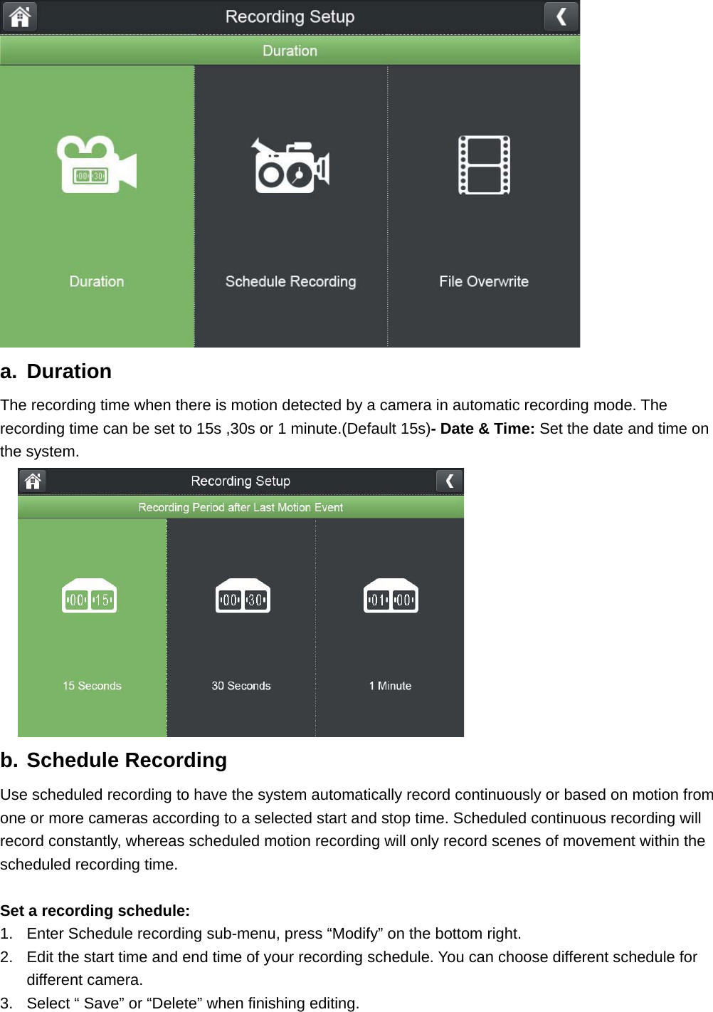
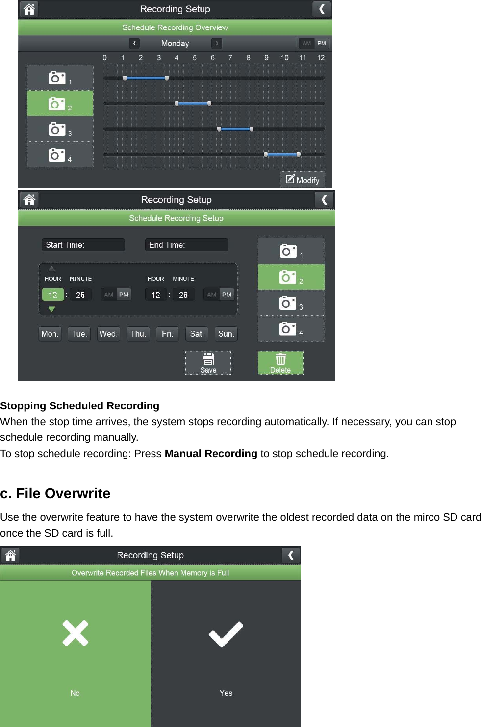
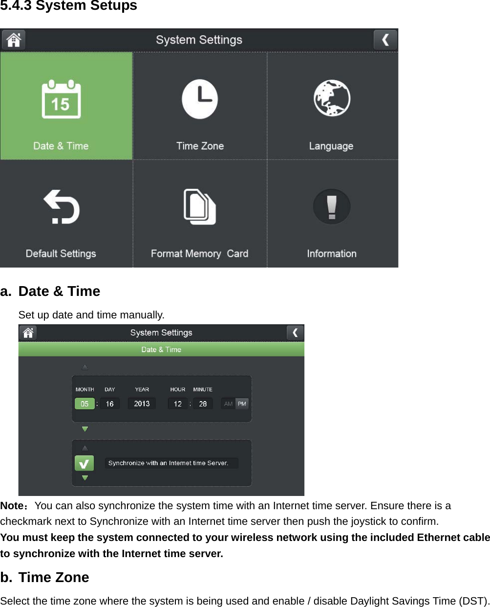
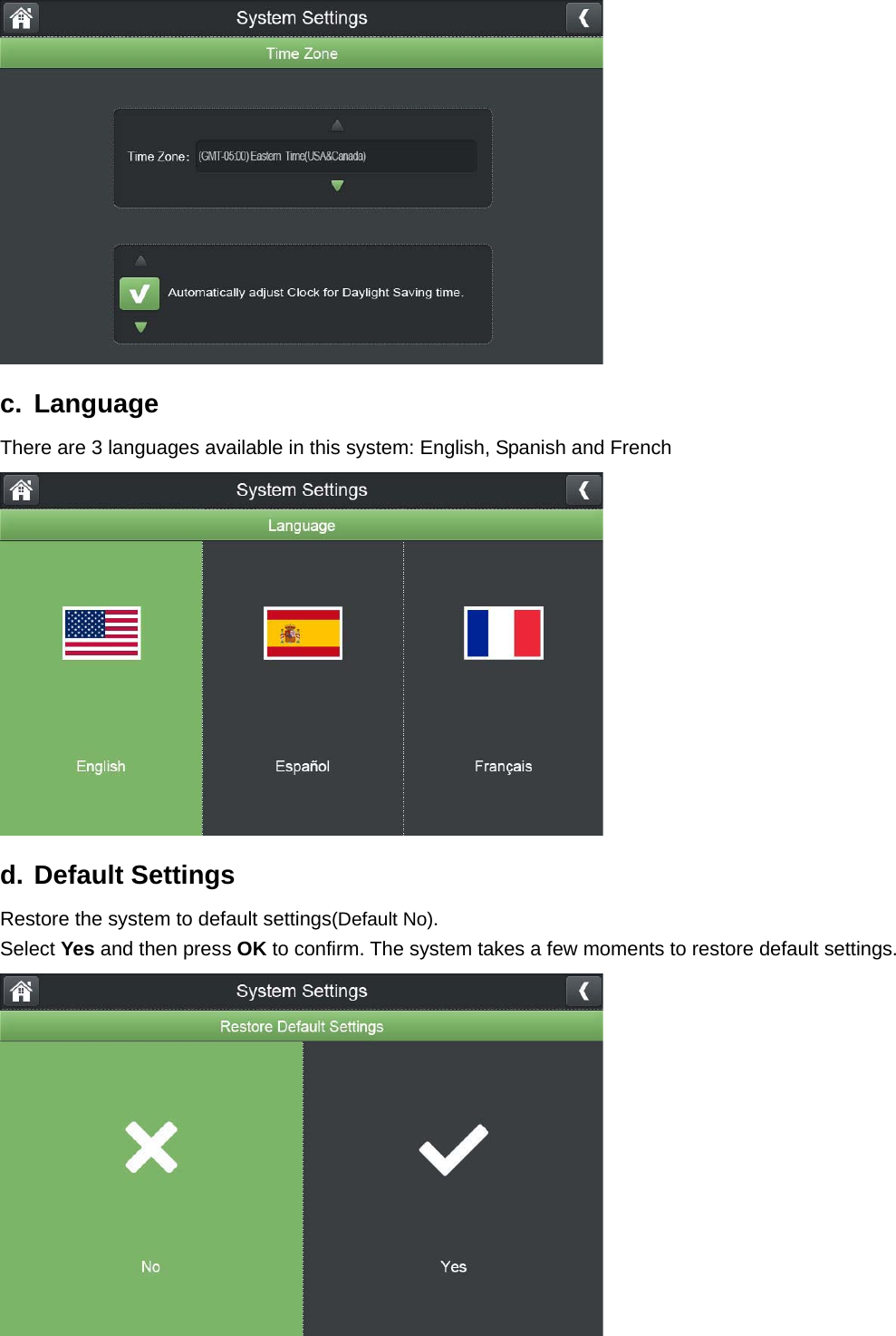
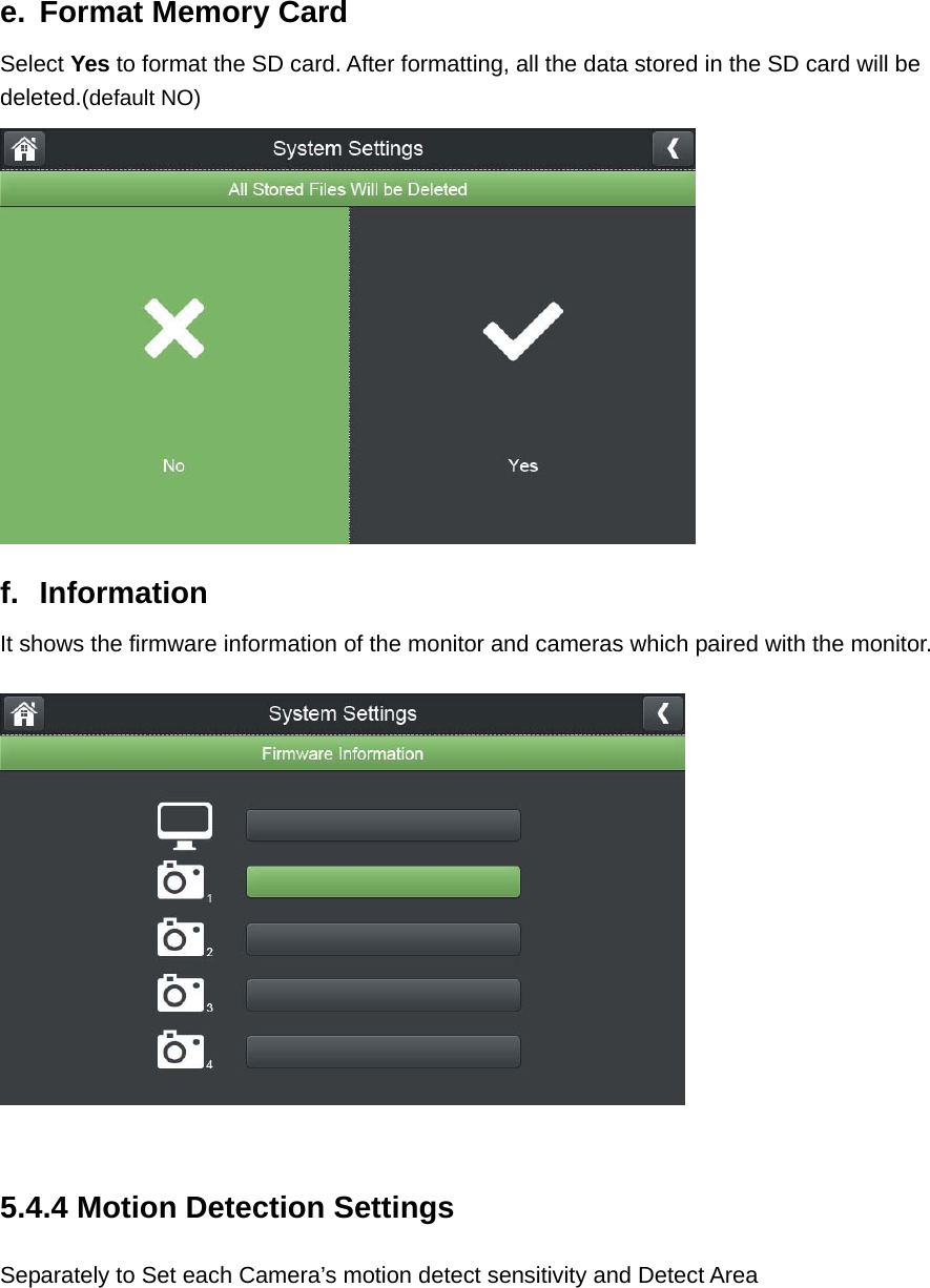
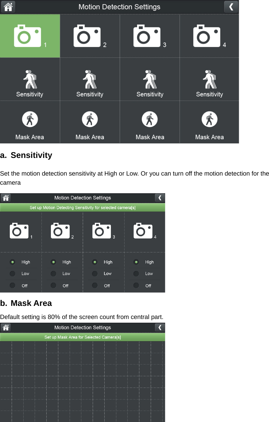
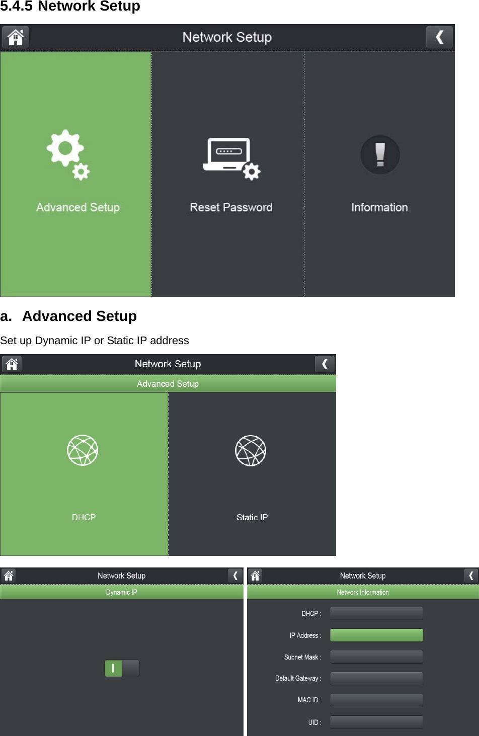
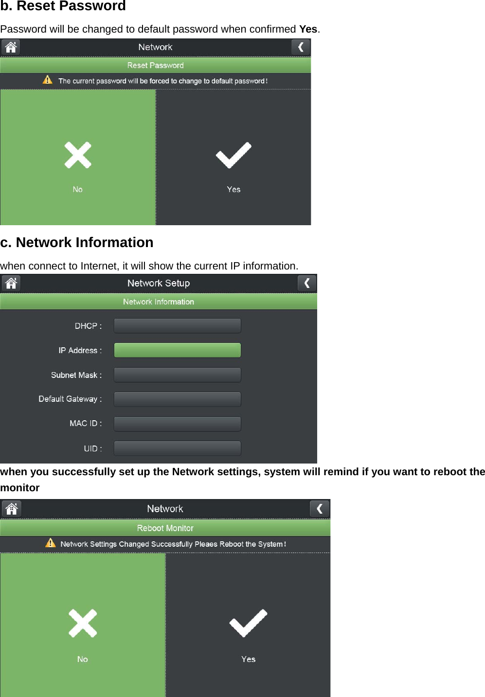
User Manual
Discussion / Help
Navigation