RDI Technology UDRC58 Guardian UDRC58 Accessory Camera User Manual UDRC58HD

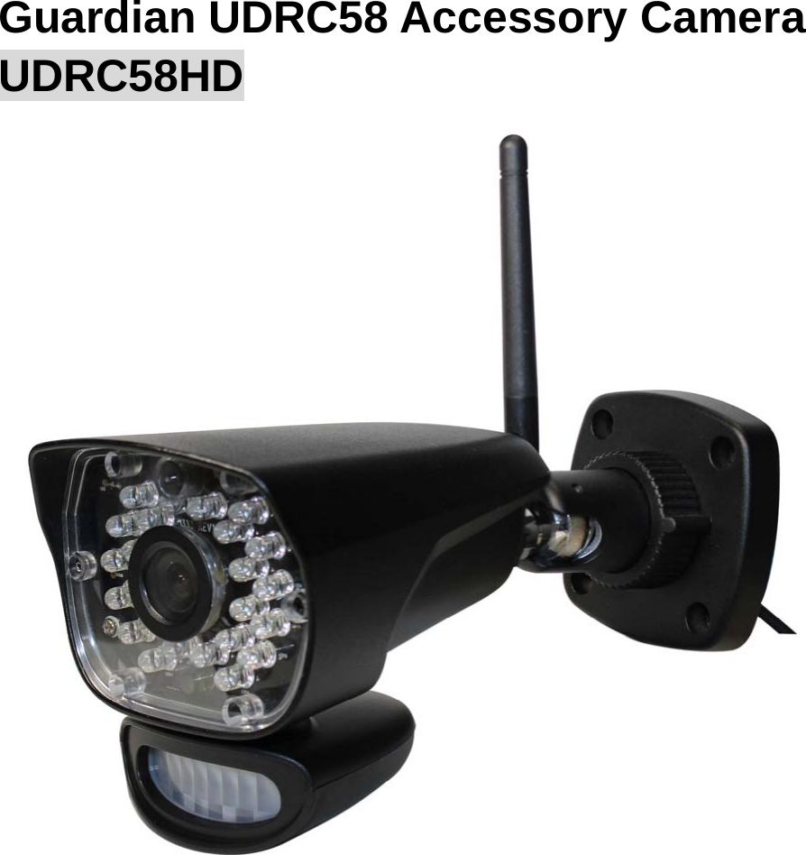
RDI Technology (Shenzhen) Co., Ltd. Guardian UDRC58 Accessory Camera UDRC58HD

User Manual

  Guardian UDRC58 Accessory Camera UDRC58HD
2  Wireless Camera                                                    1.Microphone –Captures the sound on camera side and transmits the sound from camera to receiver. 2.Night vision lights –24 pcs Night vision lights 3. Camera Lens –Catches the video in front of the lens and transmits video from camera to receiver. 4. IR LEDs – Infrared LEDs provide viewing in no/low light conditions 5. PIR Sensor – Detects motion in front of the lens and emits detection signal to transmitter. 6. Speaker – Produces the sound transmitted from the receiver.  7. Camera Antenna – Sends & receives signals to or from the receiver.  8. Wall Mounting Bracket – Use the bracket to mount the camera on a wall or other flat surfaces. 9. AC Adaptor Jack – Plug the AC adaptor to the jack for camera’s power supply. 10. Pair Button – The pair button is located on the back of the camera, it is used to pair the camera with receiver.  Note: This camera includes an Auto Mechanical IR Cut Filter. When the camera changes between day mode and night vision mode, an audible clicking noise may be heard coming from the camera. This clicking is normal, and indicates that the camera filter is working.
3  Camera Installation Before you install the camera, carefully plan where and how it will be positioned, and where you will route the cable that connects the camera to the power adaptor. Before starting permanent installation, verify its performance by observing the image on the receiver when camera is positioned in the same location/position where it will be permanently installed and the receiver is placed in the location where it will be used most of the time. Installation Warnings Aim the camera(s) to best optimize the viewing area: Select a location for the camera that provides a clear view of the area you want to monitor, which is free from dust, and is not in line-of-sight to a strong light source or direct sunlight. Avoid installing the cameras where there are thick walls, or obstructions between the Cameras and the Receiver. Night Vision This camera has built-in IR LEDs , which provides the camera with the ability to view images in no/low light conditions.    Installing the Camera 1. Carefully unpack the camera. NOTE: If you are installing cameras that did not come with the system, please see the pairing camera section of this manual for details on installation.  2. Mount the camera to the wall. Mark the position of the screw holes on the wall, and drill holes and insert 3 screws, then firmly attach the camera to the wall. Make sure to strongly secure the screw the mounting bracket into the wall NOTE: The camera can also be placed on a flat surface, such as a Table or Shelf, and no mounting hardware is required.  3. Adjust the viewing angle of the camera.    You can adjust camera angle to desired viewing area. NOTE: You can install additional cameras (maximum of 4 cameras). When adding cameras that were not included in the original box, you will need to pair up the cameras with the receiver. Refer to the camera pairing section of this manual.  Connecting Camera Power The camera can be powered by using the provided power adaptor
4  Power Adaptor Connect the power adaptor to the camera.   Make sure is the DC 9V for camera, and DC 5V for Receiver Make sure the power adaptor is placed into a grounded outlet or surge bar to protect the camera from power fluctuations.  Set Up Cameras And Monitor 1 Attach power adapters to the cameras. Plug into power using 9V,2A adaptor     2 Attach power adapter to the monitor. Plug into power using 5V,2A adaptor 3 Turn on monitor. You should see General Settings, tap and come into Camera setup.
5   Main Screen  Sub-Screen  What it Does Camera Setup Paring This system comes with cameras already paired. Use Pairing to assign these cameras to different channels or to pair additional new cameras to the monitor. ON/OFF  Makes the cameras visible to the monitor. Resolution  Adjusts the video quality of each camera.                    Pairing  Your cameras are paired to the monitor at the factory to channels 1 and 2. When you add a new camera to your system, you have to “introduce” the camera and monitor to each other so they can communicate.   You can also use this procedure to move a camera from one channel to a different channel. Some things to know about pairing cameras:  z  If a camera is already assigned to the selected channel, the pairing operation overwrites that camera link with the new one. z  Only pair one camera at a time! The monitor links to the first camera it detects. If two or more cameras are in pairing mode, you can’t control which camera the monitor will detect first.
6 Electrical Parameter: Camera(s) Transmit Frequency Range  2408Mhz~2468Mhz Data Rate  6 Mbps Transmitting Distance  150m  (Line of Sight) Image Sensor Type  PO2210N 1/2.7”FHD Cmos Image Sensor Effective Pixels  H: 1920    V: 1080 Light sensitivity  3.5 Lux (w/o IR-LEDs) Image Processing  H.264 Image Resolution / Frame Rate Cam x 2 : 1080Px1 @ 10 fps Cam x 2 : 720Px2 @ 25 fps Cam x 4 : 720Px 4 @ 15 fps Lens  3.6mm / F1.9 (ICR cut Filter) Viewing Angle (Diagonal)  92° (FOV) Daylight sensor <5 Lux (IR On), >30 Lux IR Off IR LED / Night Vision Range  1 Led / 850nm, 12m (with IR Led ) Power Requirement  9V DC 600mA ±5% Operating Temperature  14°F ~ 104°F (-10°C ~ 40°C)  Protection class  IP65 Operating Humidity  0% ~ 85%
IC Caution: IC Note : Cet appareil est conforme à la Partie 15 des règlements de la FCC et aux normes RSS de l’Industrie du Canada. Son fonctionnement est soumis aux deux conditions suivantes :    (1) cet appareil ne doit pas causer des interférences nuisibles, et (2) cet appareil doit accepter toute interférence reçue, y compris les interférences qui peuvent provoquer un fonctionnement indésirable.   Le fabricant n'est pas responsable des toutes interférences radio ou télévision causées par des modifications non autorisées apportées à cet appareil. De telles modifications peuvent empêcher l’utilisateur d’utiliser l'appareil. FCC Note: This device complies with Part 15 of the FCC rules and Industry Canada license-exempt RSS standard(s). Operation is subject to the following two conditions: (1) this device may not cause harmful interference, and (2) this device must accept any interference received, including interference that may cause undesired operation. The manufacturer is not responsible for any radio or TV interference caused by unauthorized modifications or change to this equipment. Such modifications or change could void the user’s authority to operate the equipment. This equipment has been tested and found to comply with the limits for a Class B digital device, pursuant to part 15 of the FCC Rules. These limits are designed to provide reasonable protection against harmful interference in a residential installation. This equipment generates, uses and can radiate radio frequency energy and, if not installed and used in accordance with the instructions, may cause harmful interference to radio communications. However, there is no guarantee that interference will not occur in a particular installation. If this equipment does cause harmful interference to radio or television reception, which can be determined by turning the equipment off and on, the user is encouraged to try to correct the interference by one or more of the following measures:   -- Reorient or relocate the receiving antenna. -- Increase the separation between the equipment and receiver. -- Connect the equipment into an outlet on a circuit different from that to which the receiver is connected.  -- Consult the dealer or an experienced radio/TV technician for help. To maintain compliance with FCC’s RF exposure guidelines, this equipment should be installed  and  operated  with  a  minimum  distance  of  20cm  between  the  radiator  and your body. le dispositif de a été évalués à répondre général rf exposition exigence.pour maintenir la conformité avec les directives d'exposition aux rf, ce matériel doit être installé et exploité à une distance minimale de 20 cm entre le radiateur et votre corps.

Navigation menu