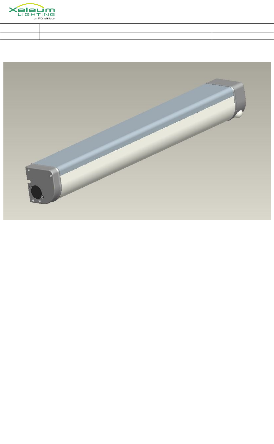
RDI Technology XASW02 WALL MOUNT STAIRWELL LED LIGHT User Manual XASW PD V2 4
RDI Technology (Shenzhen) Co., Ltd. WALL MOUNT STAIRWELL LED LIGHT XASW PD V2 4
User Manual
Stairw
Ov
Stai
back
Go
Req
W
XASW02
well Light Specifi
verview
irwell LED
kup, and RF
oal
Compli
Compli
Vandal-
Easy to
Occupa
Wireles
Battery
quireme
Use occ
Ad
dim
Max Po
Ability
Use wir
Us
and
Oc
sam
Battery
Op
Oc
8-1
Test sw
Dis
WALL MOU
ication.docx
lighting com
F system for
iant with AS
iant with NY
-resistant
install
ancy Sensor
ss RF system
backup
ents
cupancy sen
djustable tim
mmed(Rang
ower 40W
to work wit
reless RF sy
e rotary (sc
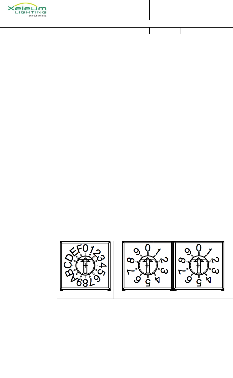
d Floor Num
Sta
ccupancy on
me Stairwel
backup
perate for 90
ccupied & R
12H battery
witch
sconnects m
UNT STAIR
mpliant wit
r linking mu
SHRAE 90.
YC LOCAL
r
m to link mu
nsor to redu
meout (after
ge 15 Secon
th wireless
ystem to link
crewdriver s
mber (00-99
airwell Num
n one floor t
ll.
0 minutes at
RF functiona
charge tim
main supply
RWELL LE
12/4/12
th modern st
ultiple light
1-2010
L LAW 47
ultiple fixtu
uce lighting
r last occup
nds to 15 Mi
remote PIR
k fixtures
set) switche
9)
mber
triggers one
t 50% light
ality the sam
e
via relay (o
ED LIGHT
tandards, w
ts.
ures for occu
to 6W when
pancy, light l
inutes)
R (To be dev
es on fixture
e floor abov
output
me as while
on 10VDC l
User Manual
SPECIFIC
DA TE:
with occupan
upancy sens
n unoccupie
level return
veloped late
e to set Stai
Floor Num
e and one fl
on mains (
line) for 30
CATION
ncy sensor,
sing
ed
ns to
er)
rwell Numb
mber
floor below
dimming).
seconds (o
Page 1 of 4
battery
ber (0-F)
within
r more

TECHNICAL DOCUMENT
TITLE: WALL MOUNT STAIRWELL LED LIGHT SPECIFICATION
REVISION: 2.4 DATE:
4/5/2013
Stairwell Light Specification.docx 12/4/12 Page 2 of 4
if pressed for longer). Controller monitors battery voltage etc and returns
status of test on test LED.
Labeled according to UL (“Diagnostic”)
Status LED(s)
One LED for self-diagnostic result
One LED for status (AC/battery charging)
Agency approvals
UL 924 rated - EMERGENCY LIGHTING AND POWER EQUIPMENT
NFPA 101 compliant (UL rating covers this)
FCC certified (RF transmitter& EMC)
AC input: 90-277VAC 50/60Hz.
Meets DLC requirements
Power Factor >0.9
THD<20%.
Min. lumen output :2000 lm
Zonal lumen: >85% 0-90°
Min. efficacy: 70LPW
CCT<5700K
Min CRI: 65
L70: 50,000hours
Warranty: 5years
PowerSupplyComponents
LightEngine
Use up to 32W light engine:
12x9 LEDs
Vf< 36V
If =<900mA
New power supply design to support charging battery and powering LEDs. Combining
the functions to save cost.
Wireless
New low-cost sub-GHz wireless system to be developed using CC430. Same micro will
act as system controller.
OccupancySensor
Use AS081 chip and new lens from XCO-100.
TECHNICAL DOCUMENT
TITLE: WALL MOUNT STAIRWELL LED LIGHT SPECIFICATION
REVISION: 2.4 DATE:
4/5/2013
Stairwell Light Specification.docx 12/4/12 Page 3 of 4
FunctionalSpecification
Normal(ACmains)operation
LEDs always on at 6W level
Occupancy sensed – LEDs on to Max power with adjustable timeout.
RF system (Microcontroller) broadcasts occupancy sensing to all fixtures on same
channel code – all fixtures respond to all occupancy events.
Battery charging
Microcontroller monitors battery, applies maintenance trickle charge when
fully charged.
Test switch
Momentary switch
Test controlled via Microcontroller
Test lasts at least 30 seconds, but longer if switch is held down longer
Internal relay interrupts DC side of PSU for test
Test LED – bi-color Red/Green
Test LED function RED GREEN
Diagnostic FAILED ON OFF
Diagnostic PASSED OFF ON
Diagnostic in progress Alt-flash Alt-flash
Status LED – bi-color Red/Green
Status LED function RED GREEN
AC Good, battery charged OFF ON
AC Good, battery charging OFF Flash
AC off, on good battery ON OFF
AC off, battery low Flash OFF
Battery FAULT Alt-flash Alt-flash
Battery fault can be:
Battery is failing to charge. Determined by microcontroller that
battery voltage is too low and not increasing at all or fast enough
Battery voltage is too high, indicating an open circuit or bad cell or
disconnected battery pack
Battery Temp too high or too low.
If battery fault continues for more than one minute, it’s assumed
there’s no battery in the fixture (non-backup version) and the Test
light is turned off.
On‐Batteryoperation
LEDs always on at 6W
Occupancy sensed – LEDs on at 50% power level with variable timeout.

TECHNICAL DOCUMENT
TITLE: WALL MOUNT STAIRWELL LED LIGHT SPECIFICATION
REVISION: 2.4 DATE:
4/5/2013
Stairwell Light Specification.docx 12/4/12 Page 4 of 4
RF system – same as on AC.
Test switch
Non-operational
Test LED – bi-color Red/Green
Indicates status of last test – see function table above
Status LED – bi-color Red/Green
See function table above
RFoperation
Three encoders
Encoder one actually sets one of 16 RF channels
Encoder two and three sets an 8-bit address.
The user just treats this as a two-digit ‘channel code’, in this case the same as
the floor number.
Depending on system testing, we may change the functionality (for example,
keep all traffic on one RF channel…) so it’s better not to expose this detail to
the user
A fixture will respond to motion events from fixtures on the same floor, or
one floor above or below.
Uses CC430 with integrated CC1101 radio
Implement simple broadcast flood meshing
Packet has a hop-count field, we have a fixed system hop-count 5
max.
When radio rx’s a packet it decrements the hop count and
retransmits the packet unless the hop count is 0.
Use collision avoidance built into radio
Proprietary XRF packet format
Allow for future options
Allow for gathering status from fixtures
Allow for use of broadcast address for queries
Broadcast ‘groups’ are the floor number settings
Motion events are broadcast to cut down on-air time
Flexible ‘report’ packets, i.e. power status
CC430 has built in UID, use it for our network UID.
Production test support
serial port status output
TECHNICAL DOCUMENT
TITLE: WALL MOUNT STAIRWELL LED LIGHT SPECIFICATION
REVISION: 2.4 DATE:
4/5/2013
Stairwell Light Specification.docx 12/4/12 Page 5 of 4
Mechanical
End caps to comply with UL HB or ar required by UL/NFPA
End cap Color Gray similar to Pantone 429U

FCC NOTE:
This device complies with Part 15 of the FCC Rules.
Operation is subject to the following two conditions: (1) this device may not cause
harmful interference, and (2) this device must accept any interference received,
including interference that may cause undesired operation.
THE MANUFACTURER IS NOT RESPONSIBLE FOR ANY RADIO OR TV
INTERFERENCE CAUSED BY UNAUTHORIZED MODIFICATIONS OR CHANGE
TO THIS EQUIPMENT. SUCH MODIFICATIONS OR CHANGE COULD VOID AND
CHANGE ANNTENA WHICH THE MANUFACTURER PROVIDES.
IT IS THE USER'S AUTHORITY TO OPERATE THE EQUIPMENT.
This equipment has been tested and found to comply with the limits for a Class B
digital device, pursuant to part 15 of the FCC Rules. These limits are designed to
provide reasonable protection against harmful interference in a resi dential installation.
This equipment generates, uses and can radiate radio frequenc y energy and, if not
installed and used in accordance with the in structions, may cause harmful interference
to radio communications. However, there is no guarantee that interference will not
occur in a particular insta llation. If this equipment does cause harmful interference to
radio or television reception, which can be determined by turning the equipment off
and on, the user is encouraged to try to corr ect the interference by one or more of the
following measures:
-- Reorient or relocate the receiving antenna.
-- Increase the separation between the equipment and receiver.
-- Connect the equipment into an outlet on a circuit different from that to which the
receiver is connected.
-- Consult the dealer or an experien ced radio/TV technician for help.
To maintain compliance with FCC’s RF exposure guidelines, this equipment should be
installed and operated with a minimum distance of 20cm between the radiator and your
body.