RESEARCH INSTRUMENTS 670854 RI Witness Sperm Prep Reader User Manual
RESEARCH INSTRUMENTS LTD RI Witness Sperm Prep Reader
User Manual

User Manual
RI Witness™
Document 6-70-121UM, Issue 13, 26th January 2015, MRF 1636
RESEARCH INSTRUMENTS LTD
Bickland Industrial Park, Falmouth, Cornwall TR11 4TA, UK
t: +44 (0) 1326 372 753 | f: +44 (0) 1326 378 783 |e: sales@research-instruments.com
www.research-instruments.com
CONTENTS
Intended Use 2
Medical Device Component 2
Applicable Part Numbers
2
Compability 3
Installaon 3
GuidanceandManufacturer’sDeclaraon(Part15ofFCC)
—ElectromagnecEmissions 5
GuidanceandManufacturer’sDeclaraon(IEC60601-1-2)
—ElectromagnecEmissions 5
GuidanceandManufacturer’sDeclaraon
—ElectromagnecImmunity 6
Safety/InformaonSymbols 8
Safety and Reliability 9
Temperature Safety 9
Mains Power Supply 10
RFID Reader Environment 10
Startup / Shutdown Procedure 10
Data Capture 12
Imaging 12
Traceability 13
Cryo 13
RI Witness™ Work Area 13
RI Witness™ Manager for Traceability, Data Capture and Imaging 14
RFID Overview 15
The Shared RI Witness™ Database 15
Hardware Overview 16
Work Area Reader Types 16
Mulplexer 17
Control Units 17
Unheated Control Unit 17
Heated Control Unit 18
Auto Tuning Readers 18
RFCalibraon 19
RIWitness™WorkAreaSpecicaonTable 20
Introducon 21
RI Witness™ RFID tags 22
TaggingPlascware 22
Dishes and Pots 22
Tubes 22
Handling RFID Tags 23
How to Switch On 24
SystemInformaon 24
ToOpentheSystemInformaon 25
How to Shut Down a Work Area 25
Logging In 25
Auto Logon 25
Logging Out 26
The WorkArea Interface 27
Performing A Procedure in RI Witness™ 28
Beginning a New Cycle in RI Witness™ 28
WitnessPointConrmaon 30
Double Witness Points 30
QuesonWitnessPoints 31
Record Witness Points 32
Unassigned Tags 32
Tag Mismatch 33
Unassigned Tag Removal 33
RecordLocaonofTags 34
Training Mode 35
ClearDemoTables(legacyworkareasforpresowareversion2.3only) 35
Admin Assign 36
Discards 36
Cycle Summary 37
CONTENTS
Daily Lists 37
Windowed Work Area 37
Language and Keyboard Layout 38
Foot Pedal Control 38
To Rename the Work Area 39
ToChangetheLocaonofaWorkArea 39
ToViewWorkAreaLocaonsorDisableaWorkArea 40
AlarmifTagsLeinWorkArea 40
Logging In 42
License Management 42
License Request Form 43
Database Management 45
InialScreen-MainMenuBuons 46
Home 46
HowtoConguretheHomeScreen 47
Paents 48
EnteringNewPaentDetailsintoRIWitness™Manager 48
EdingExisngPaentDetails 49
LookingUpPaentHistories 49
Assigning Donor Status 50
Assigning Partners 50
Cycle Types 51
StarngaNewCycle 51
Assign a Cycle Type 51
ColleconandTransferDates 52
Cycle Status 52
Revert Status 52
RIPaentIdentyLabels 53
PrinngPaentLabels 54
Label Styles 55
Operator Management 55
Operator Details 56
Group Membership 56
Enabled Operators 56
Operator PIN 56
CONTENTS
Clinic Details 56
Mismatch Comments In RI Witness™ Manager 57
The Witness Point Diagram 58
Links 59
Reassigned Tags 59
Unassigned Tags 59
Witness Point Inputs 60
MulpleSourcesoftheSameTagType 60
MulpleTagTypes 60
Entry Witness Points 60
Double Witness Points 60
Donor Witness Points 61
TaggedDonaons 61
UntaggedDonaons 62
WitnessPointQuesons 62
Witness Point Order 63
The Witness Point Log 63
Tag Types 63
ExploretheWitnessPointLog 64
WitnessPointLogStascs 64
AnIntroducontoCryoWitnessing 65
PrinngBarcodes 65
Scanning Barcodes 67
Managing Materials 68
Material Types 68
Material Type Details 69
Notes on GS1 Barcodes 70
Cycle Types 70
CreangaNewBatch 70
DelengaBatch 72
Batch Status 72
ExpiredBatches 73
View All Batches 74
CONTENTS
Paents-ManagingTreatmentCycles 74
ExcludingandIncludingBatchesforaCycle 74
AnIntroducontoDataCaptureforDataCollecon 75
Collected Data Setup 75
ParameterConguraon 76
Numerical Parameters 76
TextParameters 76
List Parameters 77
Check Parameters 77
Date, Time and Date Time Parameters 78
CalculaonParameters 78
Built In Parameters 78
Sheet Contents 78
Shared Between Sheets 79
Treatment Cycle Sheets 80
ViewingandEdingSheets 80
EdingSheetsattheWorkAreaTouchScreen 80
ViewingandEdingSheetswithRIWitness™Manager 82
Egg Parameters 82
The Number of Eggs 84
Egg Count Parameter 84
EggCountConict 84
Sheets and Witness Points 86
Cycle Summary Sheets 86
ParameterAributes 87
InialValue 87
Editable 88
Required 88
How to View Live Images 89
MulpleScreenConguraon 89
How to Take a Picture 90
How to Record Video 91
How to Zoom & Pan the Image 91
CONTENTS
How to Perform Measurements 91
How to Select Cameras 92
Camera Flipping 92
How to Set the Preset Zoom 92
HowtoConguretheFootPedal/Keyboard 92
HowtoSelectObjecves 92
HowtoAddObjecves 93
HowtoRemoveObjecves 93
HowtoCheckObjecveCalibraon 93
PaentDisplay 93
Use of Saturn™ Laser Systems with RI Witness™ 94
HowtoAccessSaturnLaserSystemInformaonfromaWorkArea 94
TemperatureProle 97
TemperatureProleChecklist 97
TemperatureCalibraon 97
TemperatureCalibraonService 98
TouchScreenCalibraonChecklist 99
Cleaning 100
Reuse Statement 101
RI Repairs System 101
Product Disposal (European Union) 101
RI Returns System 101
Contact Details 101
ObligaontoInform 101
Feedback 102
CONTENTS

Secon 1
RI Witness™ RFID Tags
1
1
Thank you for choosing RI Witness™.
The RI Witness™ family of products is made up of RI Witness™, Data Capture, Traceability, Imaging and
Cryo.
ThismanualprovidesallnecessaryinformaontouseRIWitness™.Thesystemshouldbeoperated
bytrainedpersonnelonly.Allseconsofthismanualshouldbereadandunderstoodfullybeforeany
operaonofthesystem.PleaseseetheIntendedUseformoreinformaon.
IftheoperatorisunsureofanyoftheinformaoncontainedinthismanualtheyshouldcontactResearch
Instrumentsoranappointedrepresentavebeforeaempngtousethisequipment.
In no event does Research Instruments Ltd (RI) assume the liability for any technical or editorial errors
ofcommission,oromission;norisRIliablefordirect,indirect,incidental,orconsequenaldamages
arising out of the use or inability to use this manual.
The informaon in this manual is current at the me of publicaon. Our commitment to
product improvement requires that we reserve the right to change equipment, procedures
and specicaons at any me. The latest version of the User Manual can be downloaded from
soware.research-instruments.com.TheRI Witness™ manual belongs with the RI Witness™system
and should be passed on with the system if relocated to another clinic.
The use of ™ in this manual indicates a trademark of Research Instruments Ltd. Any other brand
names,referredtointhismanual,aretrademarksoftheirrespecveowners.
© This manual is protected by copyright, all rights reserved, and no part here of may be photocopied
orreproducedinanyformwithoutthepriorwrienconsentofRI.

Secon 2
2
Introducon
2
For RI Witness™ heated work areas only.
Toidenfyandtrackhumansamplesthroughtheassistedreproducon(AR)cycleandwhererequired,
to maintain sample temperature.
Therearenocontraindicaonsassociatedwiththeuseofthisdevice.
Theheatedplate(andtemperaturecontrol)componentsofthissystemareclassiedasaclass
IImedicaldeviceinaccordancewithArcle9,AnnexIX,rule9oftheDirecves93/42/EEC&
2007/47/EC,ieit‘administersorexchangesenergy’toorfromthehumanbody.Inrespect
oftheRIWitness™system,energyisemiedintheformofheat,toorfromtheARsample.
Thereisnodirectpaentcontact.
Applicable indicaons for use are subject to the regulaons of the country into which the device is sold.
Availability of RI Witness™ for clinical use is dependent on the regulatory approval status of RI Witness™
within the country the device is intended to be sold into.
6-70-801 Sit on Top Heated Work Area Assembly
6-70-801/C Sit on Top Heated Work Area Assembly with Card Reader
6-70-801/T Sit on Top Heated Work Area Assembly with Test Tube Reader
6-70-801/TC Sit on Top Heated Work Area Assembly with Card and Test Tube Reader
6-70-802 FlushFiedHeatedWorkArea1ChannelAssembly
6-70-802/C FlushFiedHeatedWorkArea1ChannelAssemblywithCardReader
6-70-802/T FlushFiedHeatedWorkArea1ChannelAssemblywithTestTubeReader
6-70-802/TC FlushFiedHeatedWorkArea1ChannelAssemblywithCardandTestTubeReader
6-70-803 Slim Heated Work Area Assembly
6-70-803/C Slim Heated Work Area Assembly with Card Reader
6-70-803/T Slim Heated Work Area Assembly with Test Tube Reader
6-70-803/TC Slim Heated Work Area Assembly with Card and Test Tube Reader
6-70-804 FlushFiedHeatedWorkArea2ChannelAssembly
6-70-804/C FlushFiedHeatedWorkArea2ChannelAssemblywithCardReader
6-70-804/T FlushFiedHeatedWorkArea2ChannelAssemblywithTestTubeReader
6-70-804/TC FlushFiedHeatedWorkArea2ChannelAssemblywithCardandTestTubeReader

Secon 2
Introducon
3
2
RIWitness™isusedinconjunconwiththefollowing:
• Essenalmedicaldevices-dishesandtubes,maybeARornot-ARspecic.
• Nonessenalmedicaldevices-safetycabinets,incubators,micromanipulators,lasers.
• Non medical devices (general laboratory equipment), eg work benches, microscopes, PCs.
InstallaonsofRIWitness™shouldbecarriedoutbyaRItechnicianorotherRIauthorisedpersonnel.
Incorrectinstallaoncouldresultinoverallpoorperformance.
6-70-805 ITO Reader
6-70-805/C ITO Reader with Card Reader
6-70-805/T ITO Reader with Test Tube Reader
6-70-805/TC ITO Reader with Card Reader and Test Tube Reader
6-70-806 Sit on Top Heated Work Area 2 Channel Assembly
6-70-806/C Sit on Top Heated Work Area 2 Channel Assembly with Card Reader
6-70-806/T Sit on Top Heated Work Area 2 Channel Assembly with Test Tube Reader
6-70-806/TC Sit on Top Heated Work Area 2 Channel Assembly with Card and Test Tube Reader
6-70-852 SpermPreparaonWorkAreaAssembly
6-70-852/C SpermPreparaonWorkAreaAssemblywithCardReader
6-70-853 Unheated Work Area Assembly
6-70-853/C Unheated Work Area Assembly with Card Reader
6-70-853/T Unheated Work Area Assembly with Test Tube Reader
6-70-853/TC Unheated Work Area Assembly with Card and Test Tube Reader
Secon 3
Safety Warnings
3
disassembleormodifyanypartoftheRIWitness™,orsubstuteanycomponent
for any other. Doing so may result in damage to samples. This voids the warranty and/or
service contract.
To avoid the risk of electric shock, this equipment must only be connected to a
supplymainswithprotecveearth.
use the power cable and power supply adaptor supplied with the system.
The cable to the power supply is the ‘disconnect device’ for this equipment. To remove all
electrical power from this product, disconnect the power cable from the electrical outlet.
Equipmentshouldbeposionedsoastoalloweasyaccesstothepowercable.Theappliance
coupler or mains plug is used as the disconnect and must remain readily operable.
Nottobeusedinapaentenvironment.
Thesystemshouldbeoperatedbyqualiedandtrainedpersonnelonly.
Thissymbolindicatescauonarytextwhichshouldbefollowedtoavoidinjurytousersor
damage to samples.

Secon 3
Safety Warnings
5
3
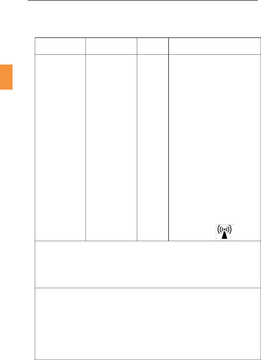
RIWitness™isintendedforuseintheelectromagnecenvironmentspeciedbelow.Thecustomeror
the user of RI Witness™ should ensure that it is used in such an environment.
RF emissions
CISPR 11 Group 2
RI Witness™ must emit electromagnec energy
inordertoperformitsintendedfuncon.Nearby
electronicequipmentmaybeaected.
RF emissions
CISPR 11 Class B
RI Witness™ is suitable for use in all establishments
otherthandomescandthosedirectlyconnected
to the public low-voltage power supply network
that supplies buildings used for domesc
purposes.
Harmonic emissions
IEC 61000-3-2 Not applicable
Voltageuctuaons/
ickeremissions
IEC 61000-3-3
Not applicable
This equipment has been tested and found to comply with the limits for a Class A digital device,
pursuanttopart15oftheFCCRules.Theselimitsaredesignedtoprovidereasonableproteconagainst
harmful interference when the equipment is operated in a commercial environment. This equipment
generates, uses, and can radiate radio frequency energy and, if not installed and used in accordance
withtheinstruconmanual,maycauseharmfulinterferencetoradiocommunicaons.Operaonof
thisequipmentinaresidenalareaislikelytocauseharmfulinterferenceinwhichcasetheuserwillbe
requiredtocorrecttheinterferenceathisownexpense.
ThisdevicecomplieswithIndustryCanada’slicence-exemptRSSs.Operaon issubject tothe
followingtwocondions:
1. This device may not cause interference.
2. Thisdevicemustacceptanyinterference,includinginterferencethatmaycauseundesiredoperaon
of the device.

Secon 3
6
Safety Warnings
3
IEC 60601
Electrostacdischarge
(ESD)
IEC 61000-4-2
± 6 kV contact
± 8 kV air
± 6 kV contact
± 8 kV air
Floors should be wood,
concreteorceramicle.
Ifoorsarecovered
withsynthecmaterial,
therelavehumidity
should be at least 30 %.
Electrical fast transient/
burst
IEC 61000-4-4
± 2 kV for power supply
lines
± 1 kV for input/output
lines
± 2 kV for power
supply lines
± 1 kV for input/
output Lines
Mains power quality
should be that of a
typical commercial or
hospital environment.
Surge
IEC 61000-4-5
± 1 kV line(s) to line(s)
± 2 kV line(s) to earth
±1kVdierenal
Mode
± 2 kV common mode
Mains power quality
should be that of a
typical commercial or
hospital environment.
Voltage dips, short
interruponsandvoltage
variaonsonpower
supply input lines
IEC 61000-4-11
<5 % UT
(>95 % dip in UT ) for
0.5 cycle
40 % UT
(60 % dip in UT) for 5
cycles
70 % UT
(30 % dip in UT) for 25
cycles
<5 % UT
(>95 % dip in UT)
for 5s
<5 % UT
(>95 % dip in UT) for
0.5 cycle
40 % UT
(60 % dip in UT) for 5
cycles
70 % UT
(30 % dip in UT) for 25
cycles
<5 % UT
(>95 % dip in UT)
for 5s
Mains power quality
should be that of a
typical commercial or
hospital environment. If
the user of RI Witness™
requiresconnued
operaonduringpower
mainsinterrupons,it
is recommended that RI
Witness™ be powered
fromanuninterrupble
power supply or a
baery.
Power frequency
(50/60 Hz)
magneceld
IEC 61000-4-8
3A/m 3A/m Power frequency
magnecelds
should be at levels
characteriscofa
typicallocaonina
typical commercial or
hospital environment.
UTisthea.c.mainsvoltagepriortoapplicaonofthetestlevel.
Secon 3
Safety Warnings
7
3
IEC 60601
Conducted RF IEC
61000-4-6
Radiated RF IEC
61000-4-3
3 Vrms
150 kHz to 80 MHz
3 V/m
80 MHz to 2.5 GHz
3 Vrms
3 V/m
PortableandmobileRFcommunicaons
equipment should be used no closer to
any part of RI Witness™, including cables,
than the recommended separaon
distance calculated from the equaon
applicable to the frequency of the
transmier.
Recommendedseparaondistance
d = [3.5/V 1]√p
d = [3.5/V1]√p80MHz to 800MHz
d = [3.5/V1√p800MHz to 2.5GHz
where p is the maximum output
power rang of the transmier in
was (W) according to the transmier
manufacturer and d is the recommended
separaon distancein metres(m). Field
strengths from xed RF transmiers,
as determined by an electromagnec
site survey, a should be less than the
compliance level in each frequency
range.b Interference may occur in the
vicinity of equipment marked with the
following symbol:
At 80 MHz and 800 MHz, the higher frequency range applies.
Theseguidelinesmaynotapplyinallsituaons.Electromagnecpropagaonisaectedby
absorponandreeconfromstructures,objectsandpeople.
Theseguidelinesmaynotapplyinallsituaons.Electromagnecpropagaonisaectedby
absorponandreeconfromstructures,objectsandpeople.
aFieldstrengthsfromxedtransmiers,suchasbasestaonsforradio(cellular/cordless)telephones
and land mobile radios, amateur radio, AM and FM radio broadcast and TV broadcast cannot be predicted
theorecallywithaccuracy.ToassesstheelectromagnecenvironmentduetoxedRFtransmiers,
anelectromagnecsitesurveyshouldbeconsidered.Ifthemeasuredeldstrengthinthelocaonin
whichRIWitness™isusedexceedstheapplicableRFcompliancelevelabove,RIWitness™shouldbe
observedtoverifynormaloperaon.Ifabnormalperformanceisobserved,addionalmeasuresmay
benecessary,suchasre-orienngorrelocangRIWitness™.
bOverthefrequencyrange150kHzto80MHz,eldstrengthsshouldbelessthan[V]V/m.
Secon 3
8
Safety Warnings
3
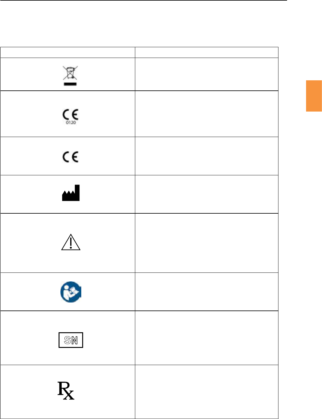
Indicatesinstruconfordisposalofgoods.
In accordance with Annex II of the European
MedicalDeviceDirecve93/42/EEC,asamended
byDirecve2007/47/ECunderthesupervisionof
noedbodyNo.0120,SGS,UKLtd.
In accordance with the European Direcve for
R&TTE,Direcve1999/5/EC
Indicates the medical device manufacturer.
Indicates the need for the user to consult the
instrucons for use for important cauonary
informaonsuchaswarningsandprecauonsthat
cannot, for a variety of reasons, be presented on
the medical device itself.
Followinstruconsforuse.
Therstfourdigitsareauniqueidenerassigned
to the product and the last 2 digits signify the year
of manufacture, eg 5001/13 (this denotes a unique
serial number of 5001 and a year of manufacture
of 2013).
Cauon: US Federal law restricts this device for
sale to or on the order of a licensed healthcare
praconer.
S
N
Only

Secon 3
Safety Warnings
9
3
Pleasereadthismanualcarefullyandfollowtheinstruconstoensurethatthesystemwillworksafely
and reliably.
Safetyistheresponsibilityofthelaboratory.Riskassessmentandworkingpraccesshouldcomplywith
local regulatory policies.
A warning triangle will be displayed on the work area touch screen and on the control unit display if the
currently selected temperature cannot be maintained.
A touch screen warning triangle will also be shown if temperature control has been disabled using the
TurnObuon.
Gently place your hand on the heated surface to verify that the temperature is appropriate for use.
Aswithallheangsystems,itisadvisabletoperformaperiodiccheckoftemperaturesusingacalibrated
thermocouple thermometer.
Secon 3
10
Safety Warnings
3
An RI Witness™ system uses readers to monitor a work area. Readers detect RFID tagged containers
that are placed in the work area.
Eachreaderisindividuallytunedtoitsenvironmentandmustnotbereposionedaerinstallaon.The
performanceofRFIDtagdeteconmaybecompromisedbyreposioningreadersandbytheproximity
ofmetalobjectsorelectricalequipmentthatwerenotpresentduringinstallaon.
Forcleaning,readersmaybeliedandreturnedtothesameposion.See“Cleaning”onpage100for
more cleaning details.
RI Witness™ hardware may be damaged by incorrect startup and shutdown procedures.
“Secon5-RIWitness™Basicoperaon”describestherecommendedstartupandshutdownprocedure
for the RI Witness™ work area.
Products from RI require a stable and noise free power supply ( 100V - 240V ). The supply must provide
anearthconnecon.
The RI Witness™ control unit for heated readers contains a mains power supply.
Secon 4
Product Overview
11
4
Welcome to the User Manual for the Research Instruments (RI) RI Witness™ System.
RI Witness™, Data Capture, Traceability, Imaging and Cryo are members of the RI Witness™ family
of products. RI Witness™ products share a common database usually referred to as the “Witness”
database.
RIWitness™isasystemwhichoperateswithinanassistedreproducon(AR)clinicsengandprovides
amethodofidenfyinghumansamplesthroughoutan AR cycle(fromegg and spermcolleconto
embryo transfer). The system is intended to minimise the risks associated with tradional/manual
double-checkingandprovidestheessenalcontrolsnecessarytoensureeggs,spermandembryosare
correctly matched and treated during the AR process.
The RI Witness™ system comprises hardware, rmware and soware components, which can be
congureddependingonthetreatmentacvies,numberofARcyclesconducted,sizeandlayoutof
the AR clinic.
RFID (radio frequency idencaon) technology provides the means of idenfying the containers
(dishes, tubes) in which eggs, sperm and embryos are transferred and stored. The containers are
labelledbyaclinicianwithaspecialRFIDtagwhichhasbeenassignedauniqueidener.Theunique
idenerislinkedtoapaent/couple(specicparentage).
As samples are processed as part of an AR cycle, RFID readers (both heated and non-heated) read the
tagson the containerand their identyand status is conrmedon-screen.If containers containing
samplesofincompableorigincomeintocontactatanystageofthisprocess,thesystemacvatesan
alarm and prompts the clinician to respond.
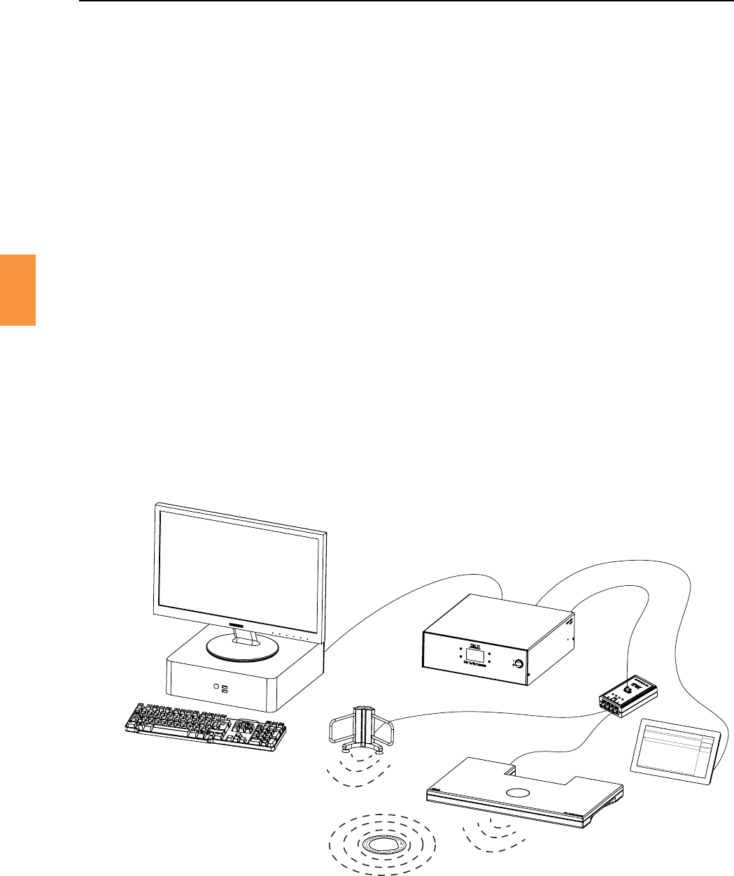
Figure 4-1 RFID tag communicang with various antennas
An antenna is incorporated into a work area reader. A control unit feeds an RF signal to the antenna. An
RFIDtagispassiveunlenergisedbythesignalfromtheantenna.Theenergisedtagthentransmitsan
idencaoncodebacktothesameantenna.SeeFigure4-1.
AnARprocedureisconductedwithinthemonitoredworkarea.Theprocedureisdenedbyasequence
of Witness Points which are presented on the touchscreen.
RI Witness
Computer Control Unit
Sit on Top Heated
Work Area Reader
RFID Test
Tube Reader
RFID Tag
Mulplexer
Touch Screen
Secon 4
12
Product Overview
4
Hand wrien notes are oen taken whilst performing laboratory procedures. For example embryo
scoresandspermvolumesmightbewriendownonadatasheetandlatermanuallytranscribedinto
aclinicferlitydatabase.
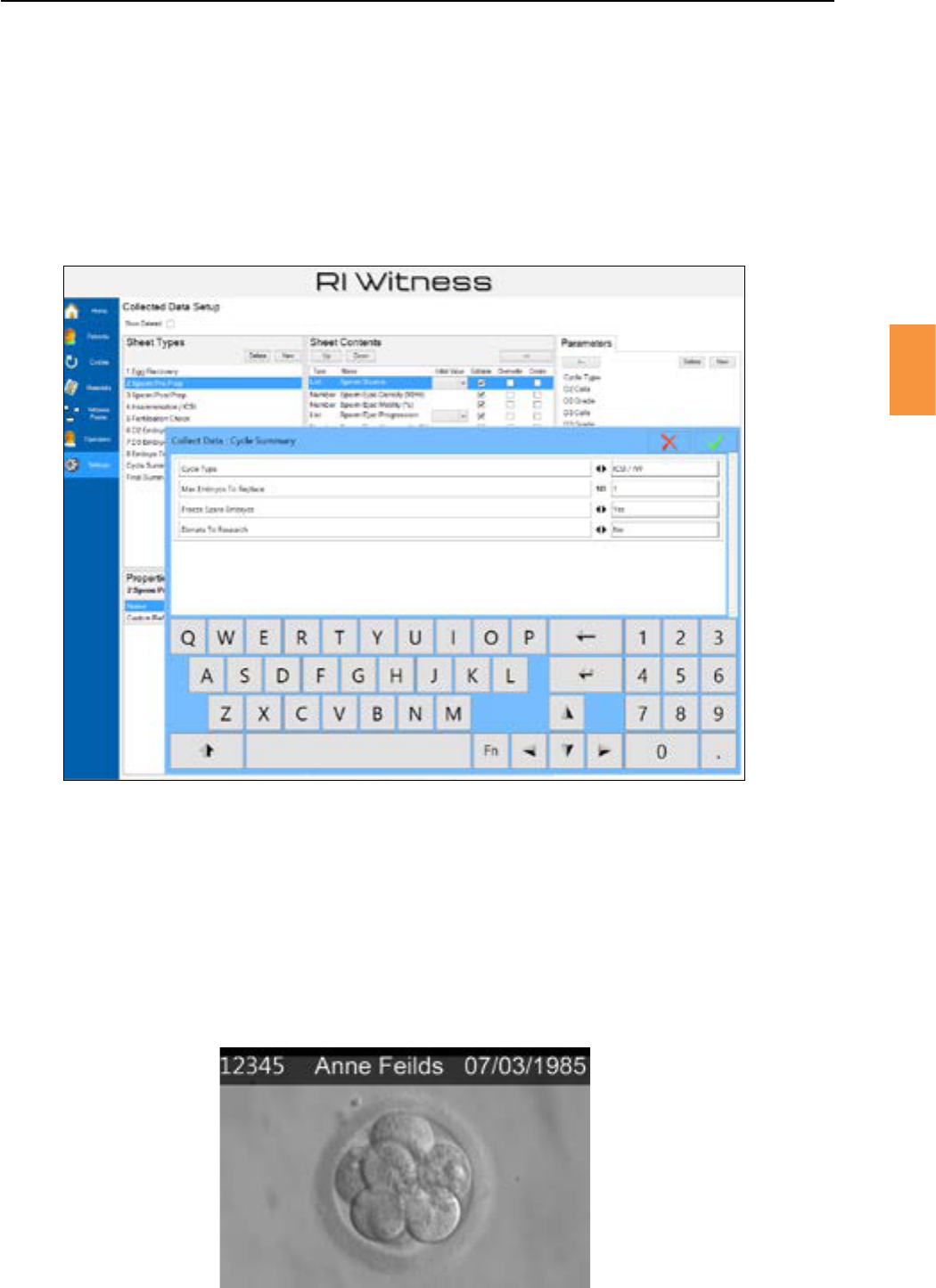
The features of Data Capture allow data sheets to be designed in RI Witness™ Manager and data entry
to be performed in the laboratory using the work area touch screen. See Figure 4-2.
Data entry may also be performed in RI Witness™ Manager.
Figure 4-2
Lower: Data entry using a RI Witness™ WorkArea touchscreen
Upper: Data sheet design using RI Witness™ Manager
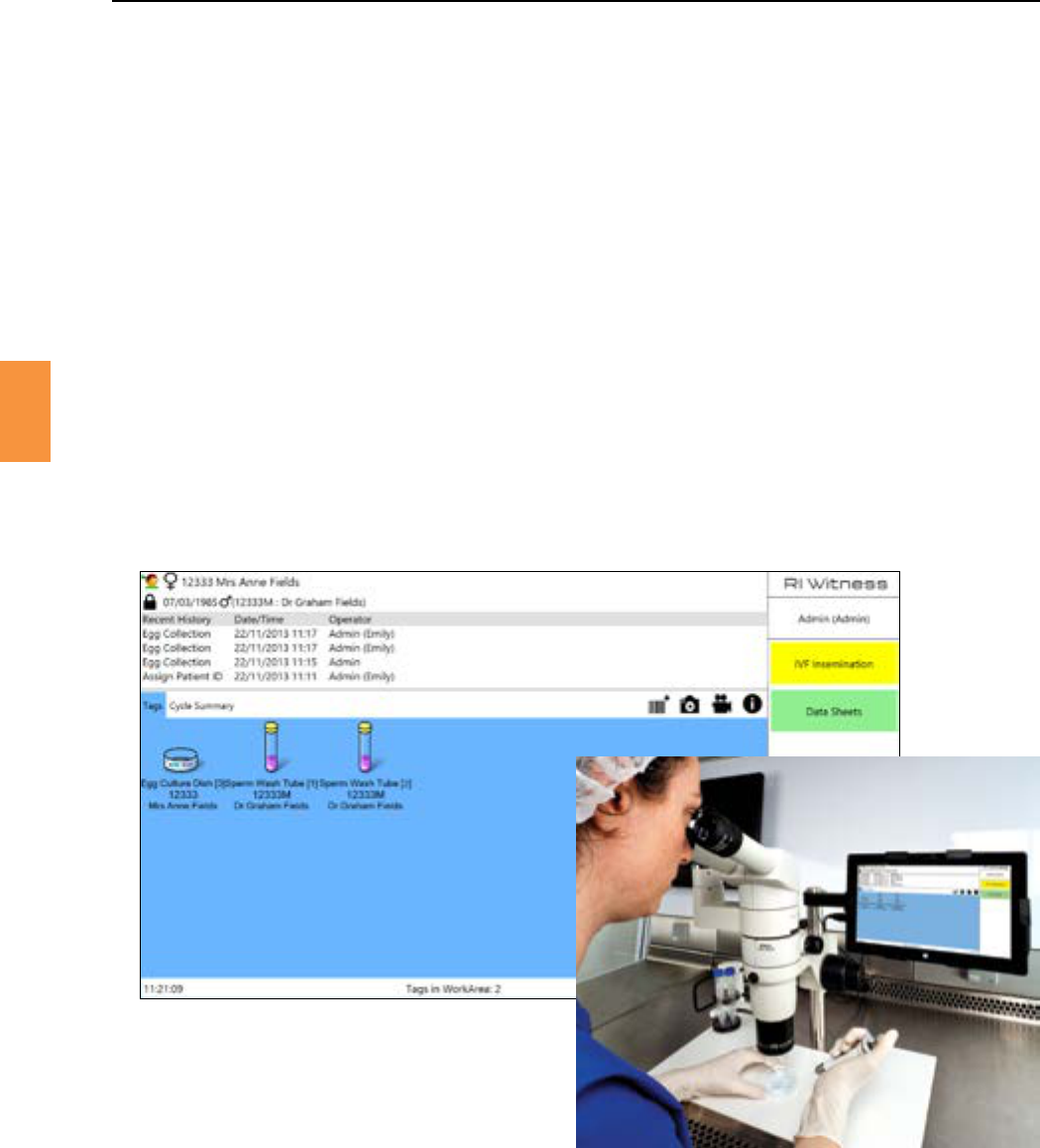
With the Imaging feature, you are able to capture images and videos from every microscope in the
laboratory,ateverystageofthepaentcycle,inrealme.Allthelatestinformaononacyclecanbe
accessed immediately from any networked PC. Images can also be sent to the embryo room to show
thepaentpriortoembryotransfer.
TheImagingfeatureiscompablewithRIIntegra™andSaturn™lasers.
Figure 4-3 Example of paent view shown in embryo room
Secon 4
Product Overview
13
4
Traceabilityisasowareproductthatlinkspaenttreatmentcycleswiththebatchesofmaterialsthat
are in use.
A barcode reader may be used to scan batches as they are delivered or made ready for use.
Thelinksbetweentreatmentcyclesandmaterialbatchesmaybeexploredtogeneratevariousreports,
forexampleareportshowingallpaentsthathavebeenexposedtoaparcularmaterialbatch.
TheCryofeatureextendstheRIWitness™securitysystem,allowingpaentsamplestobetrackedas
theyenterandleavecryostorage,creangacompleterecordofthepaentcycle.
A barcode reader is placed at the work area and used to scan a sample in or out of the cryo storage.
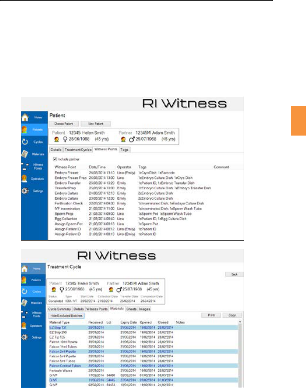
Figure 4-4 An RI Witness™ work area
RFID tagged items are displayed on a touchscreen running RI Witness™ WorkArea soware.
A typical RI Witness™ work area includes a PC, touchscreen, one or more tag readers and an RF control
unit.TheworkareaPCrunsRIWitness™WorkAreasowaretopresentanoperatorinterfaceonthe
touch screen. See Figure 4-4.
The data presented on the touchscreen is generated from the shared Witness database, all work area
events are logged to the shared Witness database.
Secon 4
Product Overview
4
RI Witness™ Manager runs on any Windows PC and provides Witness, Data Capture, Cryo, Traceability
andImagingfunconality.
The“paents”RIWitness™Managerpageisusedbyalloperators,the“materials”RIWitness™Manager
pageisuniquetoTraceabilityoperatorsandthe“witnesspoints”pageisuniquetoWitnessoperators.
See Figure 4-5.
Figure 4-5 RI Witness™ Manager is used by RI Witness™, Data Capture, Traceability, Imaging and Cryo
Secon 4
Product Overview
15
4
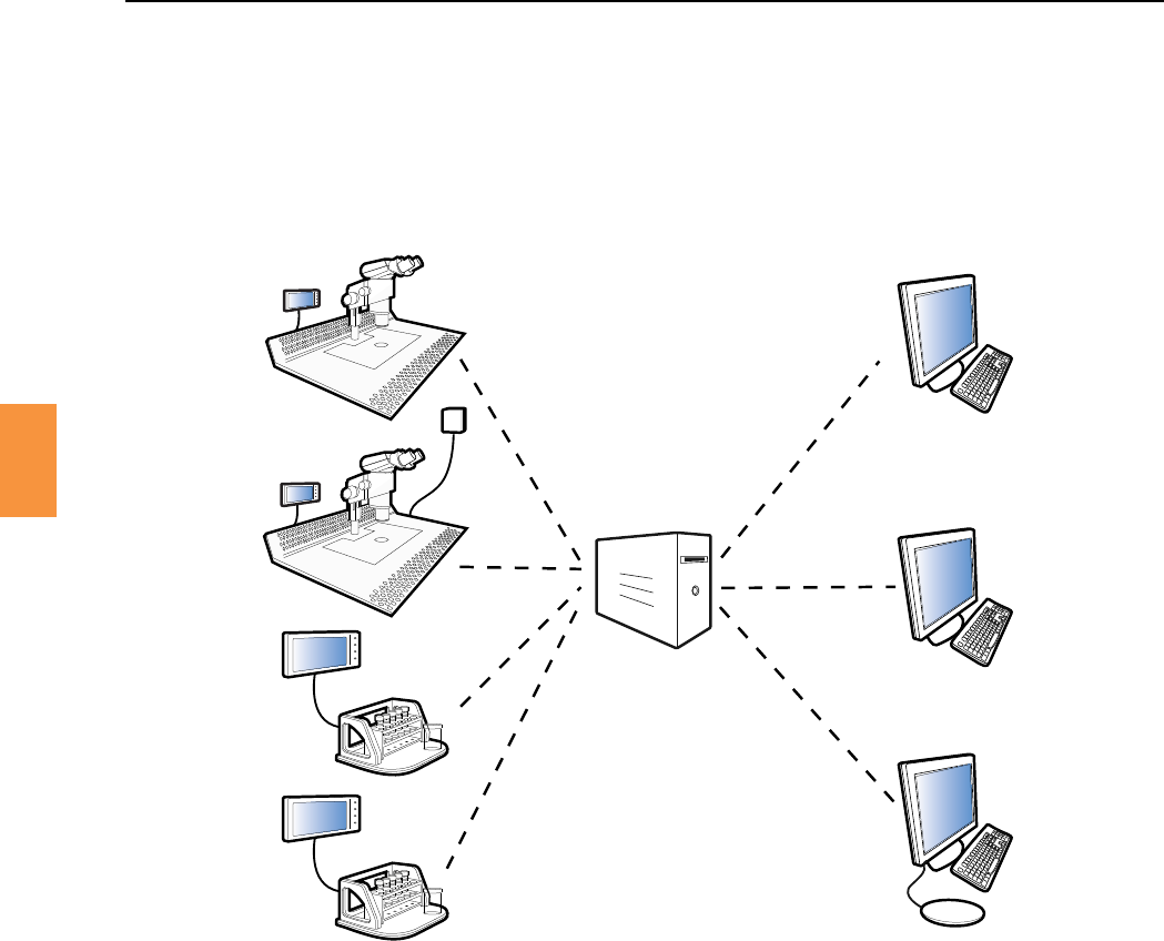
AnexampleRIWitness™installaonisshowninFigure4-6.FourworkareaswithRIWitness™WorkArea
soware, two RI Witness™ Manager PCs and an admin reader PC share a common RI Witness™
database.Traceability, RI Witness™ and DataCapturemanagementfuncons maybe performedat
each RI Witness™ Manager PC.
Lab
Manager
Work Area
Work Area
Shared RI Witness™ Database
Lab
Manager
Admin Reader
Work Area
Work Area
Figure 4-6 The RI Witness™ database is shared by All RI Witness™ WorkArea and RI Witness™ Manager PCs
Radio-frequency idencaon (RFID) is the technology used by RI Witness™ to idenfy tagged
plascware.
AcontrolunitfeedsanRFsignaltoamatchedantenna.AnRFIDtagispassiveunlenergisedbythe
signalfromtheantenna.The energisedtagthentransmitsanidencaon codebacktothe same
antenna. See Figure 4-1.
AnRFIDsystemworksontheprincipleofinducvecoupling,whichrequiresthattheantennabetuned
tomatchthefrequencyinuseandopmisedforthephysicalenvironment.Speciccablelengthsmust
beusedforallRFconnecons.
EachRIWitness™workarearequiresacomputer,acontrolunitandatleastoneantenna.Mulple
antennaworkareasrequireamulplexertoswitchtheRFsignalbetweenantennas.
Antennas are built into RI Witness™ Readers.
Secon 4
16
Product Overview
4
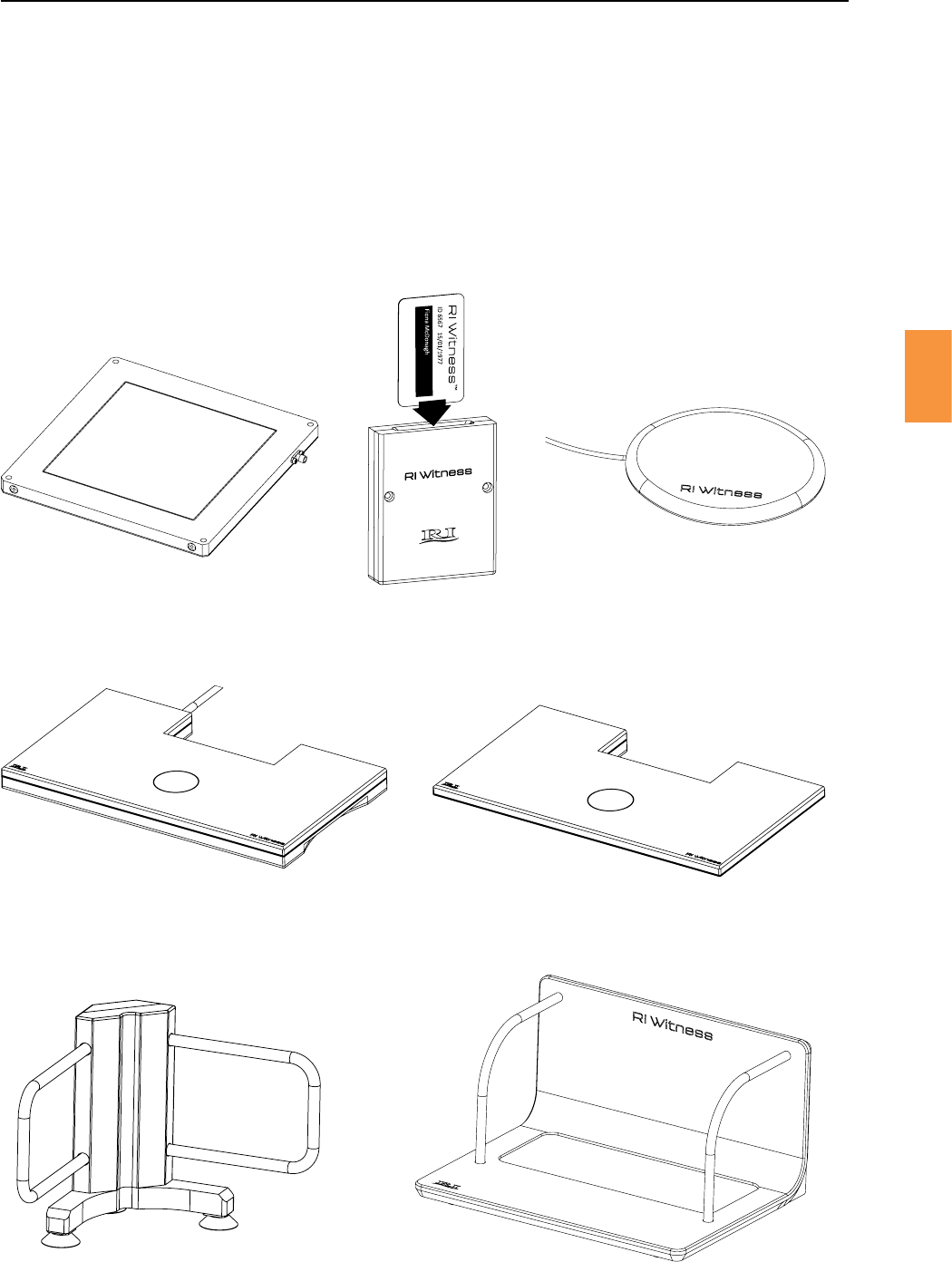
ReadersdetectRFID(RadioFrequencyIdencaon)tagsusingtunedantennas.Thetesttubereader
(2axis)andthespermpreparaonreader(3axis)useonetunedantennaforeachaxis.Allotherreaders
use a single tuned antenna.
Aushngvariantoftheheatedreaderisavailable,thisisintegratedintothesurfaceofthesafety
cabinetforeaseofuse.Legscanbeedtoallowfurtherintegraonwithotherlightbases.
Figure 4-7 ITO reader Figure 4-8 Card reader Figure 4-9 Admin reader
Figure 4-10 Sit on top heated reader Figure 4-11 Sit on top unheated reader
Figure 4-12 RFID Test tube reader Figure 4-13 Sperm preparaon reader
Secon 4
Product Overview
17
4
AmulplexerdistributesRFpowertomulpleantennas.Amulplexercanfeeduptofourantennas.
Control units provide the RF power for readers. They may be used for heated or non-heated work areas
depending on the procedures conducted there.
Figure 4-14 An RI mulplexer
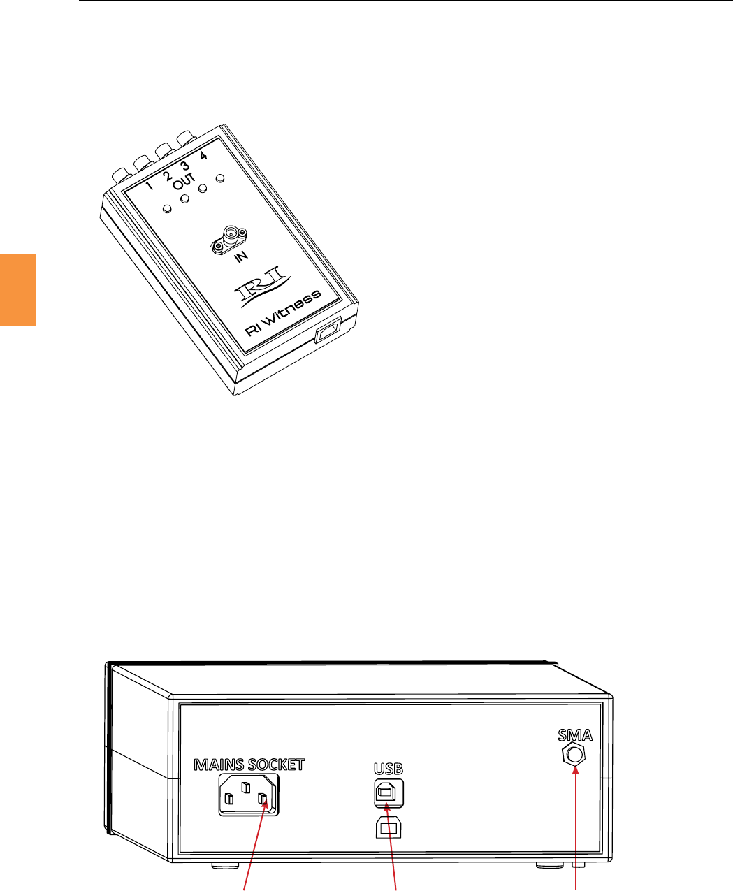
Theunheatedcontrolunitmaybeusedwithamulplexertodriveuptofourantennas.
Mains socket
USB to PC
RFCoaxialOUTtomulplexerorheatedreader
Figure 4-15 Back panel of unheated control unit
1 32
Secon 4
18
Product Overview
4
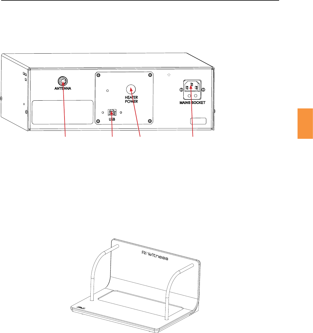
Theheatedcontrolunitcontainsatemperaturecontrollerandmaybeusedwithamulplexertodrive
up to four antennas.
1 2 3 4
1. RFCoaxialOUTtomulplexerorheatedreader
2. USB to PC
3. Heater cable to reader
4. Mains socket
Figure 4-16 Back panel of heated control unit
1. Place the reader in the desired area
2. Remove the cable clamp
3. Connect the power supply
4. Connect the Mini-USB connector
5. Replacetheretainingbracketandghtenscrew
6. Connect the USB-A connector to the PC, Tablet or USB
ConneconsaremadeupofaUSBA-Bcableandapowersupply.Thepowersupplyisa12Vpower
supplyandisexternaltothedevice.TheUSBisastandardUSB2.0cable.Thesearelocatedontherear
of the device and held in place by a retaining bracket and screw.
Figure 4-17 Sperm preparaon reader
Secon 4
Product Overview
19
4
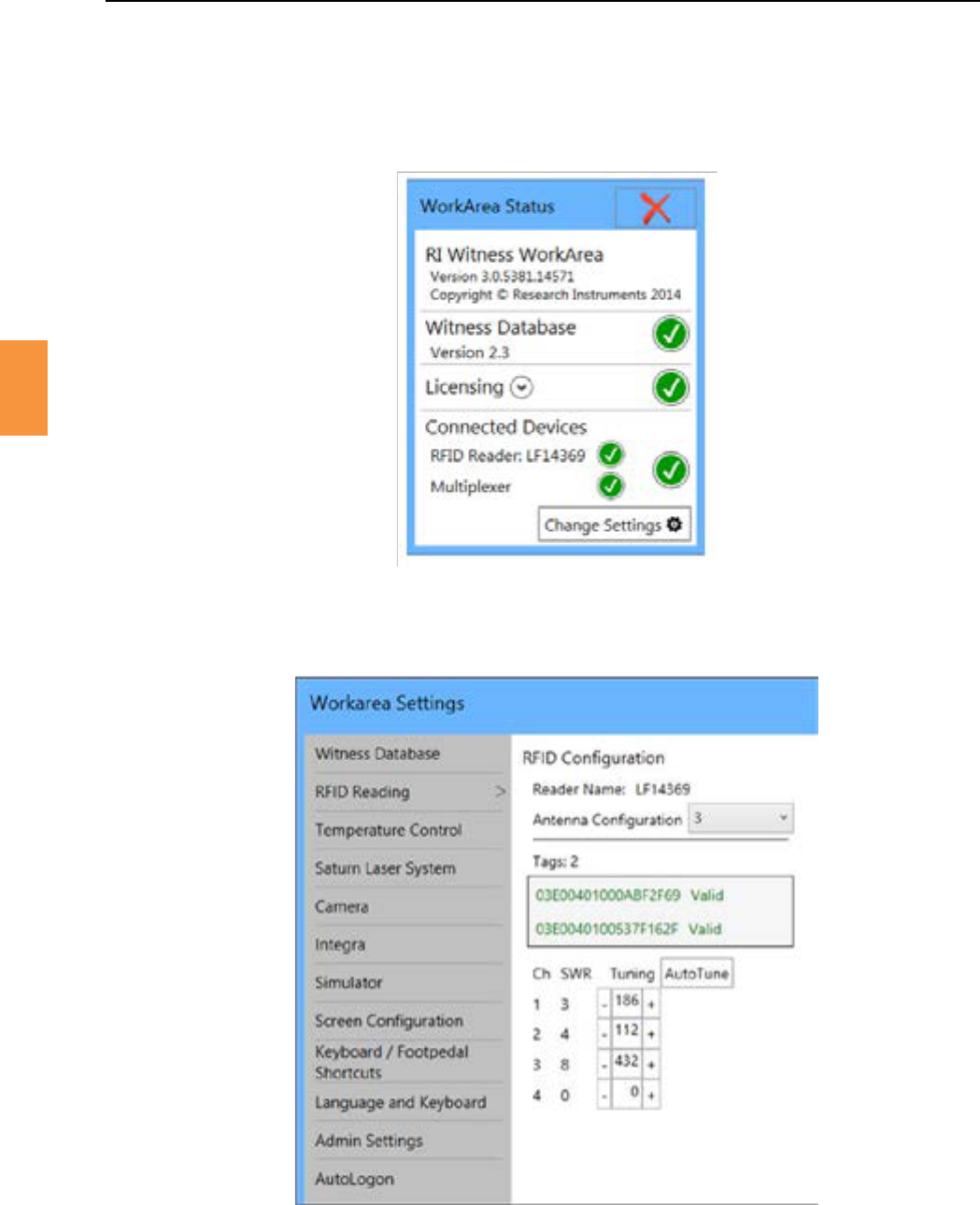
CalibraonoftheRIWitness™SpermPrepReaderismadealotsimplerbyhavinganautomactuning
system. The procedure for this is as follows.
1. OpenRIWitness™WorkArea.MakesuretheRFIDreaderandMulplexeraredetected.
2. Click the buonontheboomrightofthiswindow.
3. FromthisyouwillseetheWorkareaSengswindow.ClickontheRFIDReadingtabtobringup
theRFIDConguraonWindow.
Figure 4-18
Figure 4-19
4. FortheSpermPrep,settheAntennaConguraonto3.Thenextthingtodoistoclickon
.Thiswilltunetheantennasfortheareatheyaresituatedin.Everymethedeviceis
moved this will need to be done. This will take a few moments but when done the SWR for each
channel should show a value of 1-50. If there are any RI tags in the work area, then they will be
displayedinthegreybox.YouarenowreadytousetheRIWitness™SpermPrepReader.

Secon 4
20
Product Overview
4
HeangSystems* Heated metal and glass.
TemperatureSensor* Digital 14-bit SHT-15 or Analogue PT1000.
Displays* LCD Display. Accurate to 1 decimal place.
Connecvity USBTypeBsocketforconnecontoPC.ConnectedPCtobecompliant
with IEC 60950-1.
Supply Voltage 100-240VAC,50-60Hz,Max.2.6A,ClassI.
OperangTemperature* Temperature: 10°C (50°F) to 42°C (107.6°F).
Humidity: 15% to 85% RH (Non Condensing).
HeaterChannels* 2Channel122VDCat6AMax.Channel222VDCat1Amax.
RFID 50ΩLoadat13.56Mhz1.4WMax.I-4Antennas.
*Forheatedworkareasonly

Secon 5
RI Witness™ Basic Operaon
21
5
RI Witness™ uses one or more readers to monitor RFID tagged containers in a work area.
The work area interface is presented on a touch screen. See Figure 5-1. The operator touches screen
buonstologinandselectWitnessPoints.
Figure 5-1 The RI Witness™ WorkArea interface is presented on a touch screen
Secon 5
22
RI Witness™ Basic Operaon
5
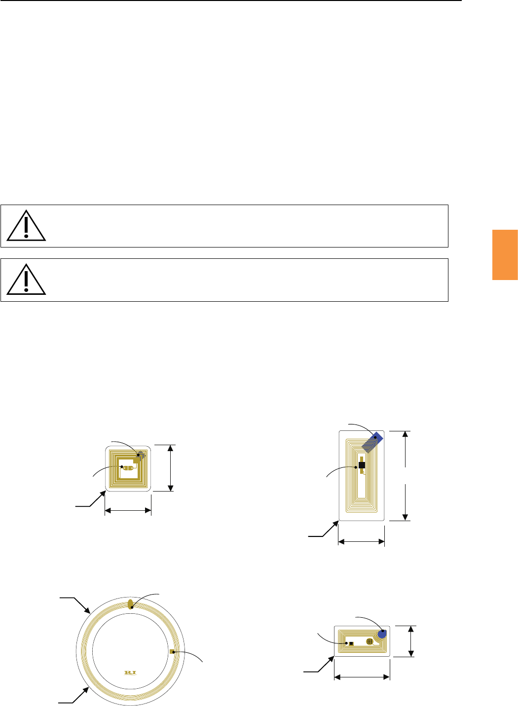
Beforeuseintheworkarea,allplascwaremustbeRFIDtaggedandlabelledwithpaentidenty.
Rectangular,circularandsquaretagsareavailable.SeeFigure5-2.Thesampleidentymaybeassigned
totheRFIDtagoncethetaggedplascwareisplacedinaRIWitness™workarea.
RFIDtagsmustbeposionedonthebaseofdishesandpots.Thesquaretag,posioneddiagonally,is
recommended for a four well dish.
Figure 5-2 RI Witness™ tags
Therectangulartagisrecommendedfortubes.Posionthelongedgeofthetagalongthelengthof
thetubeandholdinplaceusingtapeorapaentidentylabel.Posiontagsnearthetopoftubesto
ensure they are not obscured by thermal blocks or tube warmers.
Rectangular Tag
Square Tag
Circular Tag
Dia 43.8mm Bridge
Chip
Peel from here
36 mm
18 mm
Bridge
Chip
+ UPM
Peel from here
18 mm
18 mm
Bridge
Chip
+ UPM
Peel from here
375_1
+
22 mm
12 mm
Peel from here
Chip
Bridge
Time-Lapse Tag
Secon 5
RI Witness™ Basic Operaon
23
5
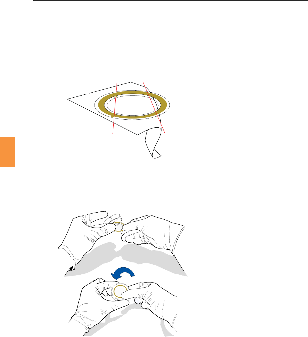
When removing tags, bend the backing strip away from the tag, rather than the tag away from the
backing strip. This will reduce the risk of damaging tags.
1. Startpeelingthebackingstripawayatthe“peelfromhere”pointshowninFigure5-3toachieve
a peel line as shown.
chip and bridge line peel line
Figure 5-3
Figure 5-4
2. Whensckingthetagtothedish,bringthetagintocontactwiththedishatonepoint.Thenuse
yourngerorthumbtoworkthetagontothedishwithacircularmovement,movingawayfrom
theinialcontactpointsoastoavoidanykinksinthetagasitsckstothedish.SeeFigure5-4.
Unusedtagsandunusedtaggedplascwareshouldnotbestoredonornearasurface(safetycabinet
or workbench) where a RI Witness™ reader is located.
Secon 5
RI Witness™ Basic Operaon
5
RI suggests that you keep the RI Witness™ computers and work areas switched on. This means that the
heangandmonitoringisconstant.
IfyouhaveswitchedoaheatedRIWitness™workarea,pleaseallow45minutesfortheworkareato
return to the required temperature. Please check there is power at the wall socket, the PC and touch
screen (or tablet) and control tower.
You may want to check the work area heang and touch screen calibraon for accuracy before
commencingwork.See“Secon12-TemperatureCalibraon”onpage97.
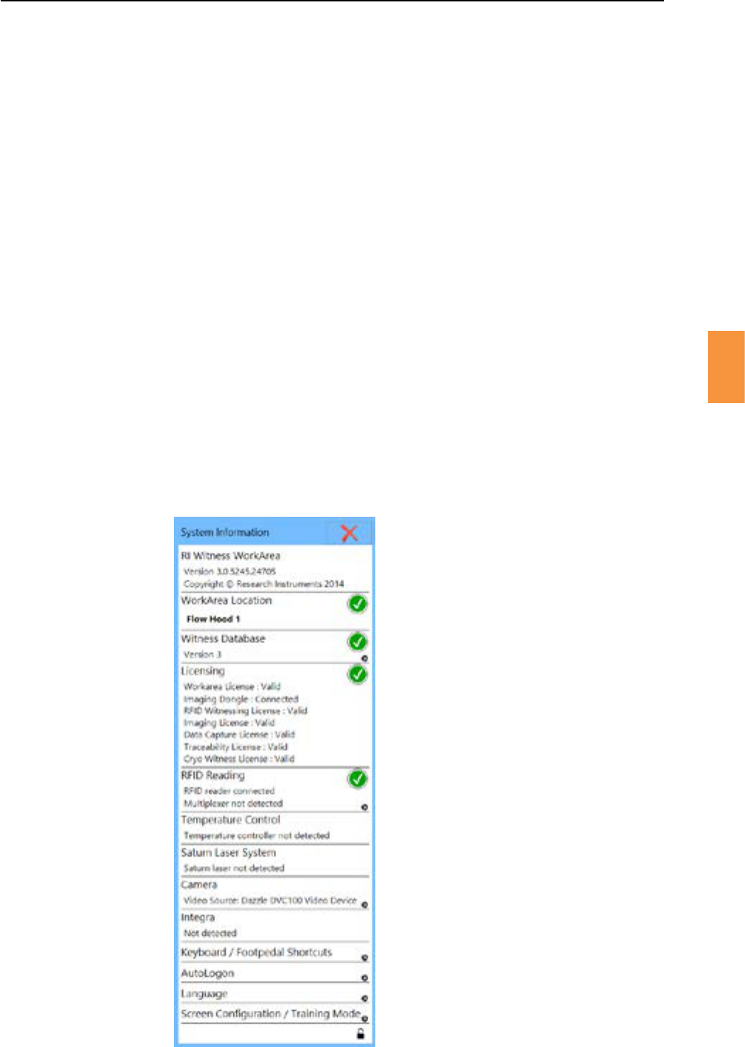
Thesysteminformaonpanelwillshow:
1. Versionnumbersforsowareandrmware
2. Workarealocaon
3. Database version
4. Licensing status including Imaging dongle
5. RFIDreaderstatusandmulplexer
6. Temperature control status
7. Saturn™LaserSystemstatus,serialnumber,rmwaredetails
8. Camera status
9. Integra™ status
6
1
2
3
5
7
8
9
Figure 5-5
Secon 5
RI Witness™ Basic Operaon
25
5
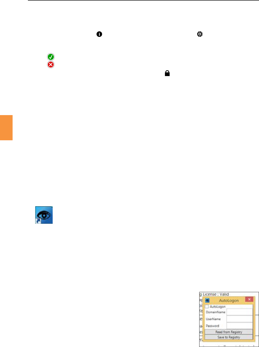
Figure 5-6 RI Witness™ WorkArea icon
1. Press the icon in the work area or click the icon from the Imaging
screen.
2. TheSystemInformaonwindowshowsthecurrentstateoftheRIWitness™system.
3. Indicates there is no problem.
4. Indicates a problem needs resolving.
5. InsystemInformaon,clickingontheclosed attheboomofthepagewillunlock
alltheexisngconguraonsengsandalsorevealthefollowingsengsthatarehiddenwhen
theSystemInformaonislocked:
• Keyboard / foot pedal controls
• Auto logon
• Language
• Screenconguraon
TheSystemInformaonislockedbydefaultandclickingontheagainwillre-lockthesengs.
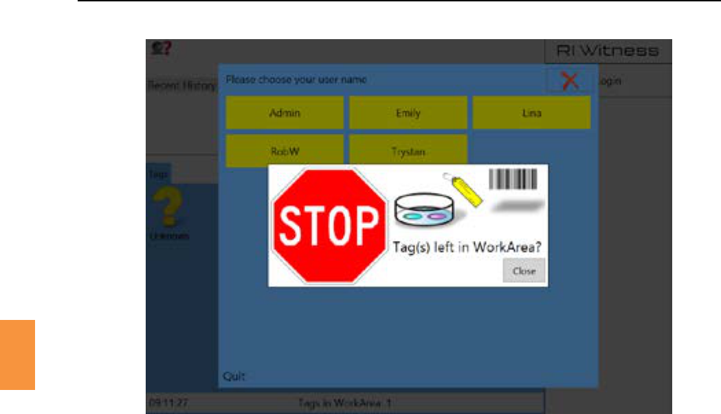
DonotswitchoanyRIhardwarewhilsttheWorkAreasowareisrunning.Tologout,selecttheuser
name, and then select in the user name window. The system will then shut down. See Figure 5-8.
ItisimportanttoensurethatallRIWitness™hardwareisswitchedonbeforetheworkareasoware
isacvated.
TheRIWitness™sowaremaybeacvatedautomacallywhenthecomputerisstarted.Ifnot,double
click the desktop icon.
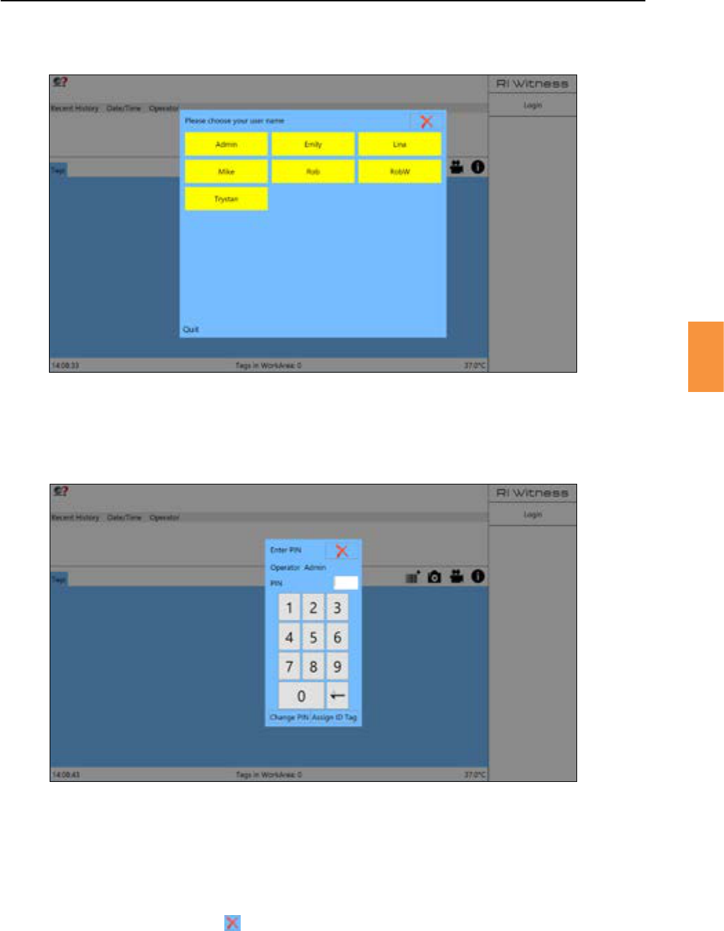
To log in either touch then your username or scan your operator ID tag and enter the appropriate
4 digit PIN if requested.
Operators can change the PIN assigned by the administrator and may assign an ID tag. See Figure
5-9.
Aerunlockingthesysteminformaon,screennavigatetotheautologonsecon.Thereyoucansetup
the username and password (of the machine) for RI Witness™ to auto logon the PC.
1. Click
2. Unlocksengs.
3. Click
4. Click to the user message.
5. Enter the details required (contact IT department if unsure).
6. Click
7. Tick
8. Click the close window cross.
Oninstallaonoftheapplicaontheapplicaonshortcutisplacedinthestart-up.Thiscausesthework
areatoautomacallystartwithwindows.
Figure 5-7 AutoLogon
Secon 5
26
RI Witness™ Basic Operaon
5
Logoutoftheworkareawhenyouhavenishedyourproceduresbypressingyour in the
top right corner, then the .Anautomaclogoutmaybeprogrammedaeraperiodof
inacvity.ThisissetusingtheRIWitness™ManagerSengspage.
Figure 5-9 RI Witness™ WorkArea logon and PIN entry windows
Figure 5-8 Logging into RI Witness™
Secon 5
RI Witness™ Basic Operaon
27
5
The WorkArea interface screen is divided into 7 regions. See Figure 5-10 .
Thisregionshowsthecurrentpaentname,dateofbirthandID.Whentagsfrombothpartners
arepresentthenameshownwillbethefemalepaent.Thepartner’snamewillappearin
brackets.
Therecenthistoryregionpresentsthefourmostrecentaconsthathavebeenrecordedagainst
thecurrentpaent,egwitnesspoints(acon/protocolstep),operatormismatches,etc.A
mestampandoperatornamearealsoshown.
The work area region displays an icon for each RFID tag detected by the work area. As
tags progress through the witness points of a procedure they are assigned and reassigned
appropriately.Aquesonmarkiconwillbeshownforanytagsthathaveyettobeassignedan
identybytheRIWitness™system.
The status region summarises the work area contents. It is recommended that the number of
tagsdisplayedinthestatusareaisvisuallyconrmedateachstageofaproceduretoverifythat
each tag has been detected.
For heated systems this region displays the temperature of the work area. Click the temperature
readout to show a window from where the temperature may be set.
Emily
Figure 5-10 The WorkArea interface
1
2
3
5
6
7
Secon 5
28
RI Witness™ Basic Operaon
5
Thewitnesspointsregiondisplaysoponsavailableforthenextstepasspeciedbythelab
denedprotocol.Thetoponeistheprecedingaconandthecurrentcontentsoftheworkarea
determinewhatnextstepsarepossible.Anadministratorwillalsoseeanoponto
assign or reassign dishes outside of the prescribed protocol.
Thecurrentoperatorregionshowswhoisloggedon.Asux(Admin)isaddedforoperatorswho
belongtotheadministratorgroup.Allwitnesspointsperformedwillbeaributedtotheoperator
whoisloggedinatthatme.
Bringthedishortubeyouwishtoworkonintotheworkarea.Ifthetaghas beenidenedbyRI
Witness™thepaentandthehistorywillbeshownonthescreen.Theoponsforthenextaconswill
be shown in yellow on the witness point region.
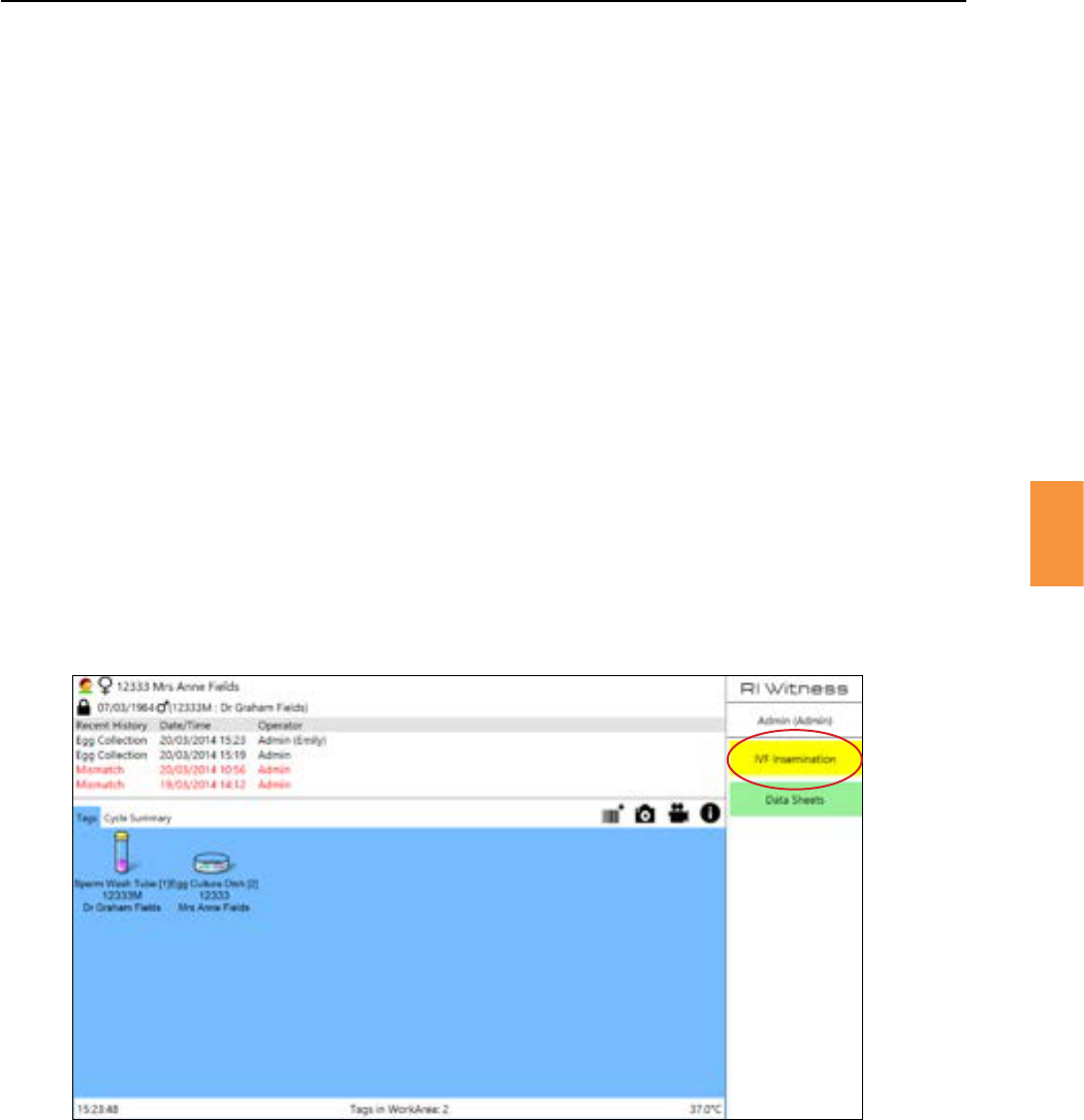
Intheexampleshownbelowa“SpermWashTube”andan“EggCultureDish”havebeenplacedinto
the work area and RI Witness™ has determined that the only appropriate procedure is represented by
the witness point. See Figure 5-11.
Figure 5-11 The IVF inseminaon witness point is the only match for the contents of this work area
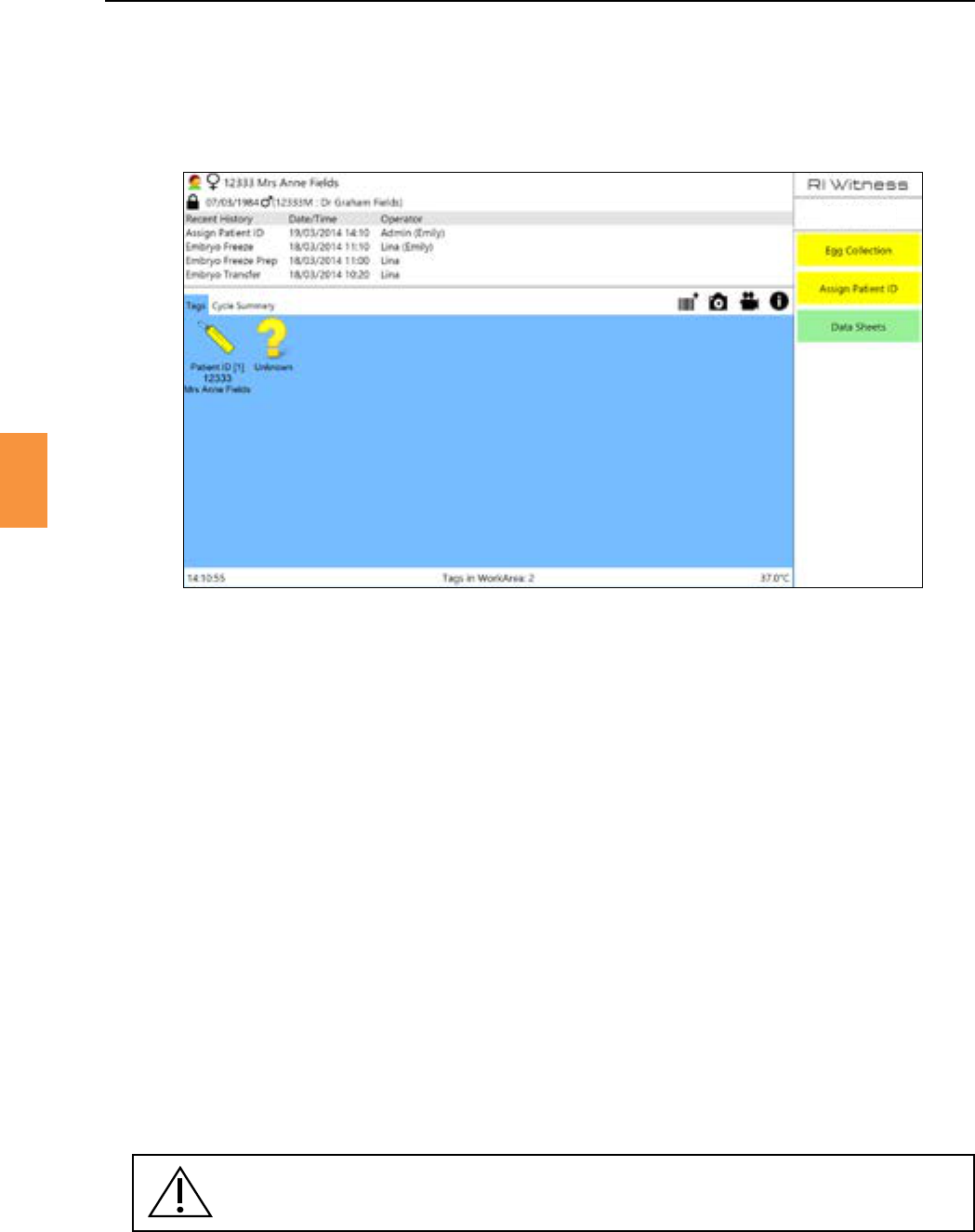
TherststepintheRIWitness™procedureiswhentheidentycardforthepaentisassigned.This
isthemostimportantstepintheprotocolasiftheidentyofthepaentiscorrectlyassignedatthis
point, the security of the cycle is assured.
Secon 5
RI Witness™ Basic Operaon
29
5
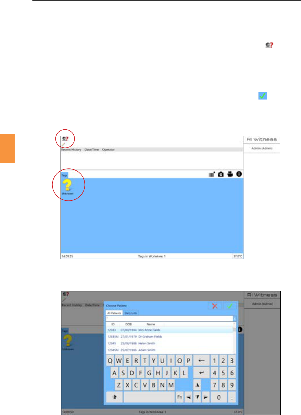
Figure 5-12 Unassigned tag has been detected
Figure 5-13 Choose Paent/All Paents window to assign ID
1. To start a new procedure, log in then place one or more unassigned, tagged items into the work
area(usuallyapaentIDcard,eggcollecondishorspermpot).Ayellowquesonmarkwill
show that the tag has been detected and is unassigned. See Figure 5-12. Press the icon.
2. In the tabtypethepaentnameorIDnumbertolocatethecorrectpaentinthe
database. See Figure 5-13.
3. Alternavely,thetabshowsallEggColleconsandEmbryoTransfersscheduledfor
theday.ClickthepaentcycleforeitherEggColleconorEmbryoTransfer,thiswilldisplaythe
chosenpaentsdetailsintheworkarea.
4. Choosewhichaconyouintendtoregister/performandthenclickthe icon again.
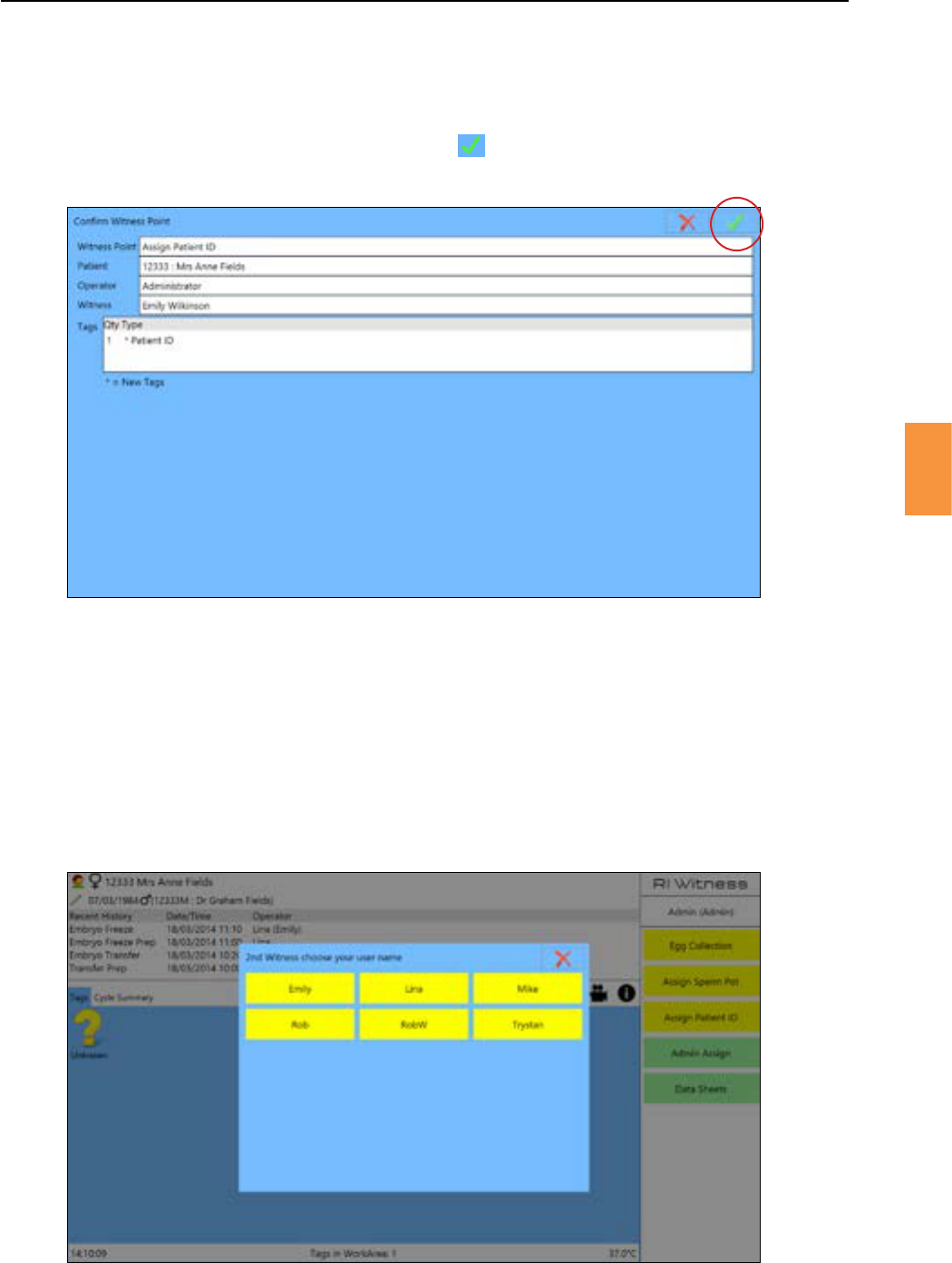
5. If a double check by another person has been set at this point, a 2nd Witness window will
appear.ThisrequiresacolleaguetoverifytheaconbyinpungtheirnameandPIN.See
“DoubleWitnessPoints”onpage30.
Secon 5
30
RI Witness™ Basic Operaon
5
Ateverystepintheprocedure,awitnesspoint(acon)mustberegisteredinthesystem.Therefore
whenanaconisperformed,selecttherelevantwitnesspointandconrmbycheckingthedetailsin
theconrmaonwindowandclickingthe icon .
Figure 5-14 Conrming a witness point
Figure 5-15 A double witness point
Cricalpoints,asdenedbytheadministrator,mustbewitnessedbyasecondoperator.Thesecond
witness must enter their PIN. See Figure 5-15.
Secon 5
RI Witness™ Basic Operaon
31
5
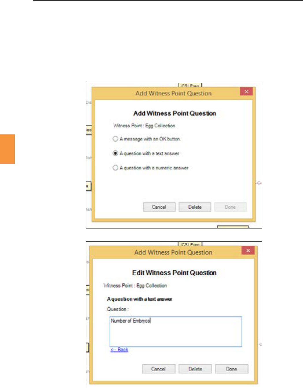
Queson Witness Points, as dened by the administrator, require a response from the operator.
ExamplesoftextandnumericquesonsareshowninFigure5-16andFigure5-17.
The Witness Point queson and the operator response is displayed during the nal witness point
conrmaonwindow.Thequesonandresponsealsoformpartofthehistoryloggedforthisevent.
Figure 5-16 Add witness point queson
Figure 5-17 Edit witness point queson
Secon 5
32
RI Witness™ Basic Operaon
5
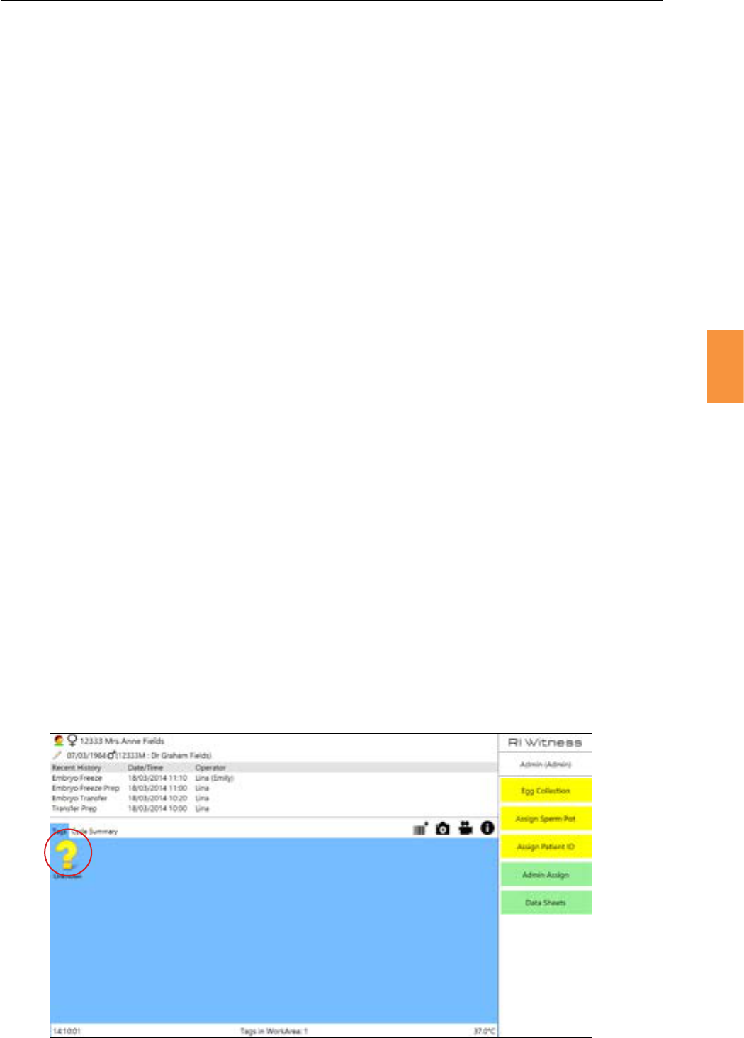
Thetagsonunusedplascwareareunassignedandareshownasaquesonmarkiconintheworkarea
display. SeeFigure5-18.Whenselecngawitnesspointunassignedtagsareautomacallyassignedto
thepaentcurrentlydisplayedonthescreen.Theywillbeidenedasthesampletagdenedbythe
witness point.
Figure 5-18 The queson mark icon represents an unassigned tag
Gatherallthe(tagged)plascwarethatarerequiredtoperformaprocedureandplacetheminthe
work area.
Awindowrepresenngtheworkareawilldisplayallthetagsandshowtheidentyofanytagsalready
“known”tothesystem.
An acve paent is selected either manually or automacally; manually by clicking on the
seconoftheworkareaandchoosingapaentfromthelist,orbythesystemautomacally
selecngthepaentidenedbythetagsintheworkarea:
• Ifthereisonepaentintheworkareathenthisisthecurrentpaent.
• Ifthereare2paentsintheworkareawhoaremale/femalepartnersthenthefemalepaentis
thecurrentpaent.
• Ifthereare2ormorepaentsaeradonaonwherethepaentsaredonor/recipient(s)then
thedonoristhecurrentpaent.
Alistofpossiblewitnesspointsisshown,determinedbytheselectedpaentandvisibletags.Choose
the appropriate witness point.
Ifthewitnesspointisataggeddonaontype,thentherecipientwillneedtobechosenfromalistat
this point.
Ifthewitnesspointrequiresfurtherinformaonenteredbytheoperator,thenthiswillbeaskedfor.
If the witness point requires a 2nd witness, then another operator will now need to choose their name
and enter their PIN.
Aconrmaonwindowsummarisesallthedetailsrelangtothewitnesspointthatwillberecorded.
Ifallthedetailsarecorrect,thenselecngtheckwillrecordthewitnesspoint.
If any new tags are added to the work area during the processing of a witness point (or admin assign)
then the witness point will be cancelled. Also, if during the processing of a witness point one of the tags
in the work area drops out of range of the reader(s), then the witness point can be completed and the
tag(s) will be reassigned successfully.
Secon 5
RI Witness™ Basic Operaon
33
5Figure 5-19 Unassigned tag removal
A warning is displayed when an unassigned tag is removed from the work area. See Figure 5-19.
Thismessageinformstheoperatorthatanunassignedtagenteredandexitedtheworkareawithout
being registered in the current procedure. If that is correct selectandconnue.Ifnot,replace
the sample/labware in the work area and perform a witness point.
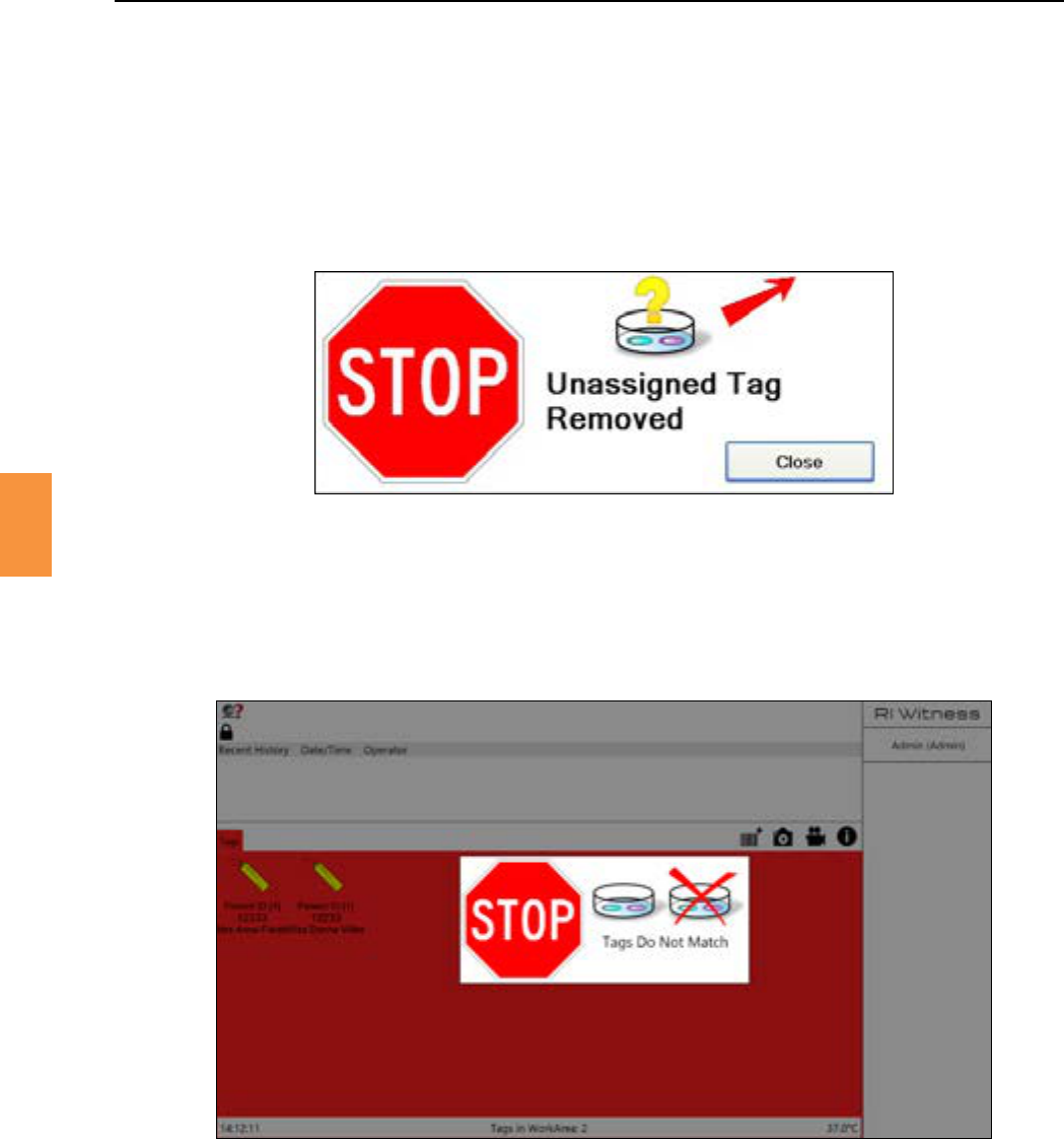
TheRIWitness™systemwillonlyallowonepaent(withdonor)oracouple’ssamplestobeplacedina
workareaatanyme.Ifanunlinkedsampleisplacedintheworkarea,aconnuousalarmwillsoundand
a mismatch window will appear immediately. The message is displayed.
Figure 5-20 Tag mismatch
1. Remove the samples in order to stop the alarm and select to close the window.
2. Amismatchreasonwindowisdisplayed.Theoperatormustenteranexplanaonforthemismatch
beforeworkcanconnue.Theexplanaonwillappearinbothpaents’cyclehistoriesandwillbe
visibleintheRIWitness™Managersoware.
:Ifthemismatchoccurredwhilenooperatorwasloggedin,anexplanaonforthemismatchis
associatedwiththeoperatorexplainingbutnotthemismatchitself.
Secon 5
RI Witness™ Basic Operaon
5
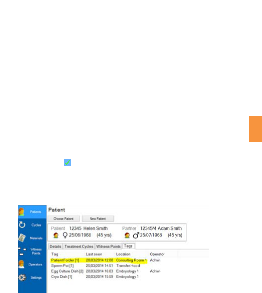
Ateachworkarea,alocaonnamecanbesetthroughtheSystemInformaonwindowthatuniquely
idenesthatworkarea.InRIWitness™Manageralistofalltheconguredlocaonscanbeviewed.
Whenatagisplacedintoaworkarea,thelocaonwillbestoredwiththetagdetails;thenwhenthe
tagsassociatedwithapaentaredisplayed,theirlastknownlocaonwillalsobedisplayed.SeeFigure
5-21.
Thenameofeachworkareacanbecongurediniallybyanyuser.Anadministratorcanmodifyany
locaonname.AlistoflocaonscanbeseeninRIWitness™Managerfromwheretheycanbedisabled
andenabled.Disablingalocaonwillcausetherelatedworkarea’snametoberesettoUnknownsoit
canthenberenamedbyauser.Anydisabledlocaoncanbere-enabled.Thiswillsetitsnamebackto
the previous value.
To name a work area:
1. Whentheworkareaisstartediniallyyouwillberequiredtogivetheworkarealocaona
name.Anyusercaniniallysetthenameofaworkarea.Aredcrossiconwillappearaswellas
the icon as a warning triangle.
2. Click the toopensysteminformaon.
3. Unlockthesengs.
4. Click .
5. Enteralocaondescripon/name.
6. Click the Icon .
Whenawitnesspointiscompleted,thelocaonatwhichittookplacewillberecorded.
PCs connected to the RI database must have unique computer names, if connected to a domain
this will be set, otherwise please check.
Figure 5-21 Tags tab
Secon 5
RI Witness™ Basic Operaon
35
5
Fortrainingandtesng,anyRIWitness™workareamaybesettoTrainingMode.
1. Log in as an admin operator.
2. Open .
3. Select .
4. Thenckthebox.
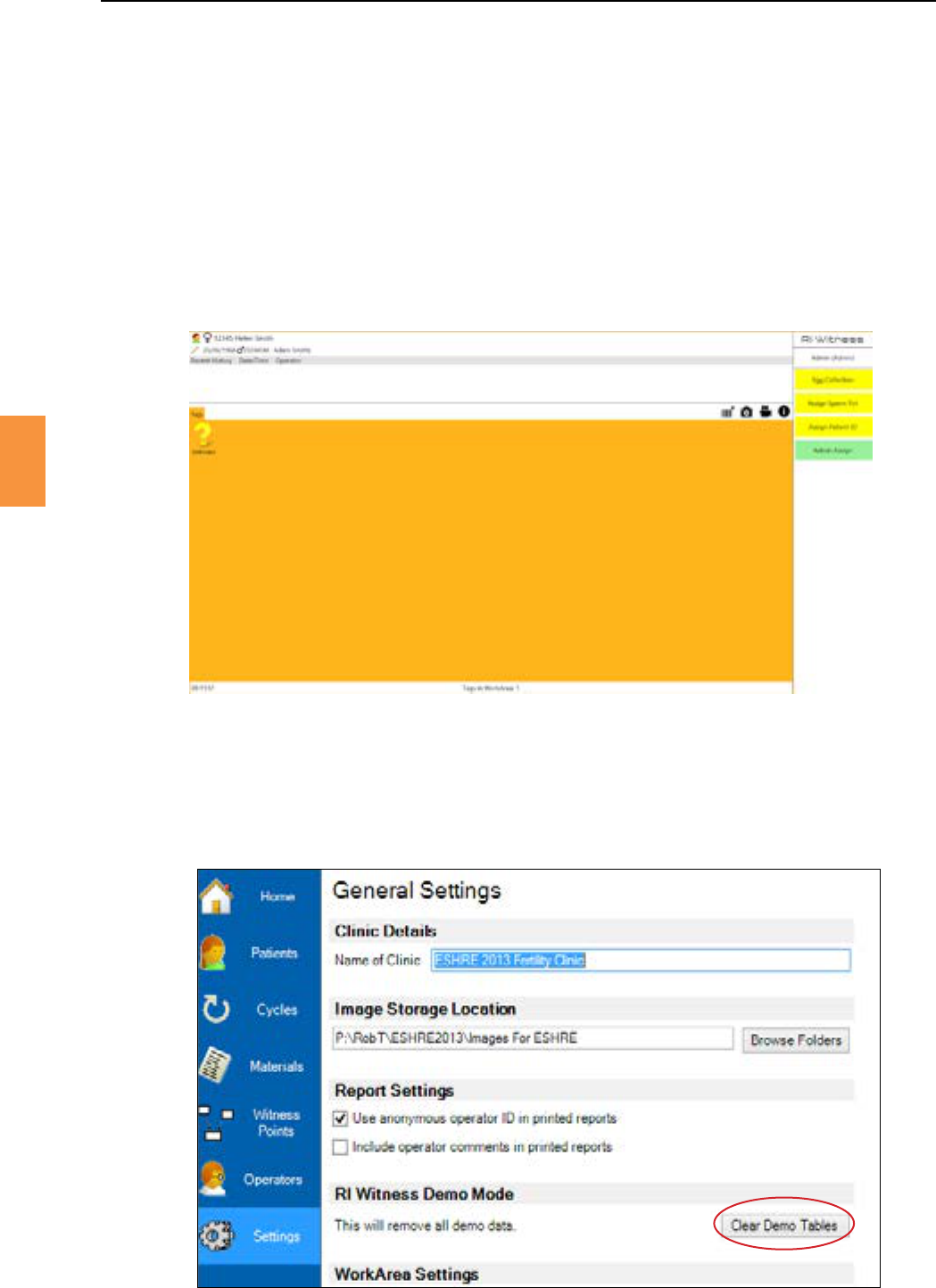
In Training Mode, the normal work area screen is replaced with an orange background. See Figure 5-22.
OnloggingoutofTrainingMode,thetrainingworkareaeventswillautomacallybedeleted.
Figure 5-22 Training mode
Figure 5-23 The RI Witness™ Manager general sengs page
Training work area events are stored in a demonstraon database which may be cleared using RI
Witness™ Manager. An admin operator may click on the page of
RI Witness™ Manager. Figure 5-23.
Secon 5
36
RI Witness™ Basic Operaon
5
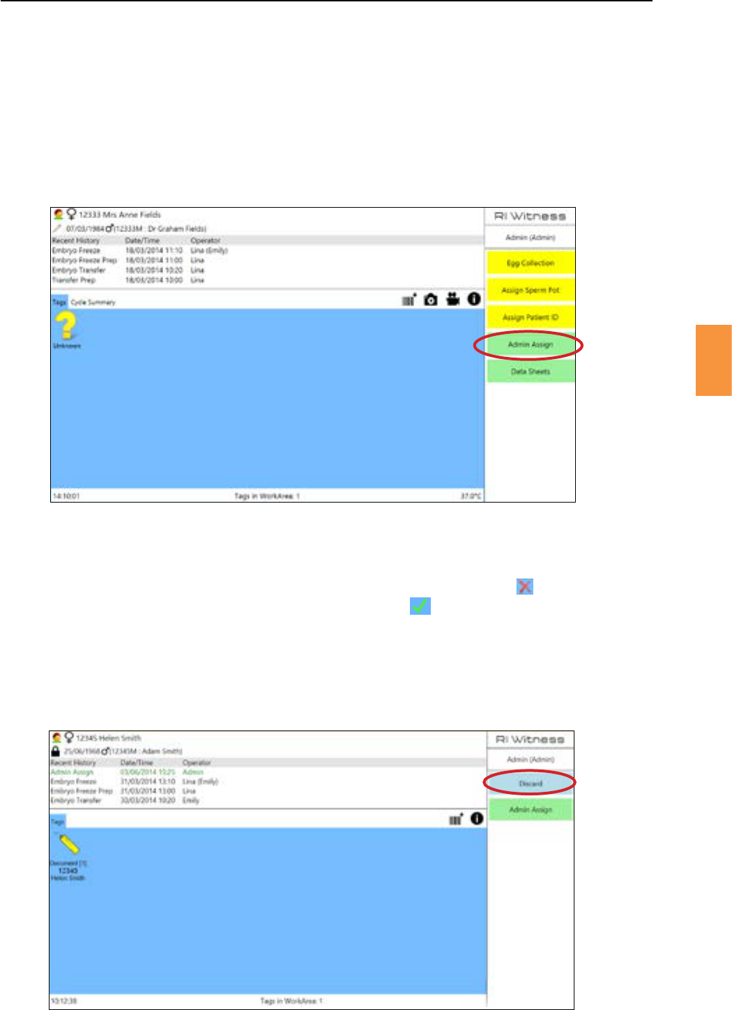
Designated operators may use the buon,seeFigure5-24,toassignanytagtype(sperm
pot, inseminated dish, sperm wash tube, etc) to an unassigned tag at any point.
:AdminAssignshouldonlybeusedunderexceponalcircumstancesandbytrainedpersonnel
only.
WithAdminAssignyoucanalsochangethetypeofdishalreadyassignedtoapaent.
Figure 5-24 Admin assign
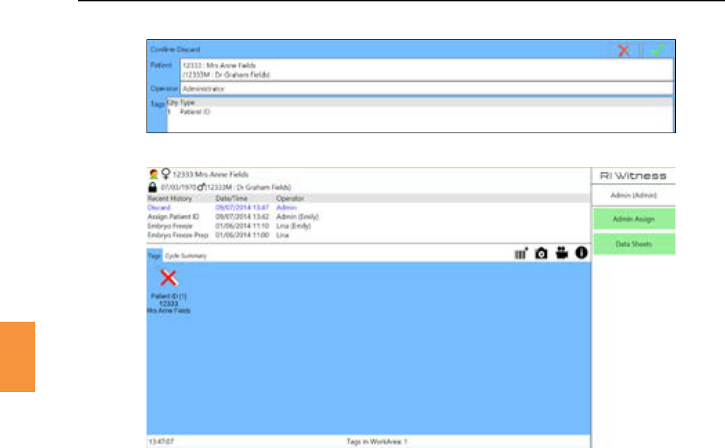
When a single tag is placed in the work area the buonisenabled,seeFigure5-25.Pressingit
willdisplayaconrmaonscreenwithagreenckandredcross.The will cancel the
discardandclosetheconrmaonwindow,whilstthegreenck will mark the tag as discarded -
changinghowitisdisplayedintheworkareaandprevennganywitnesspointstakingplacewhilstitis
in the work area.
ThereisalsotheoponfromwithinRIWitness™ManagertoenableDiscardstorequireaWitness.
Onceenabled,awitnesswillbepromptedtologinonthescreenfollowingtheoperatorselecngthe
buon,aerasuccessfullogintheconrmaonwindowwillbedisplayedasusual.
Figure 5-25 Discard
Secon 5
RI Witness™ Basic Operaon
37
5
Thecyclesummaryisdisplayedintheworkareaatallmes;itisadatasheetthathasbeenselectedto
beshownfromtheRIWitness™Manager.Ifapaentisnotselected,orthereisnocyclesummaryfor
aselectedpaent,thecyclesummarydisplaywillsay.Iftheselectedpaent
contains a cycle summary sheet, this sheet will be displayed in the area.
Onthepaentselectwindow,youcanselectthedailylistwhichshowinglistofpaentsfortoday.The
dateisdisplayedinthetopleofthewindow.Tochooseanotherdateandviewitsrelatedprocedures,
clickontheleandrightarrowsatthetopofthewindow.(Thelearrowmovesthedatebackoneday
andtherightarrowadvancesthedatebyoneday).Toselectapaent,clickonthepaentIDnumber.
Foradminstaonswithadminreaders,theWorkAreaapplicaoncanbewindowedtoalloweasyaccess
tothetagreadingfunconality.
1. OpentheRIWitness™WorkAreaapplicaon.
2. Click
3. Unlockthesengs.
4. Click / .
5. Tick .
6. Click and .
7. Ifyouhavemulplescreenssetup,theworkareawillnowreverttoonesingleworkarea
screen.
Figure 5-26 Conrm discard
Figure 5-27 Discard in the work area
Secon 5
38
RI Witness™ Basic Operaon
5
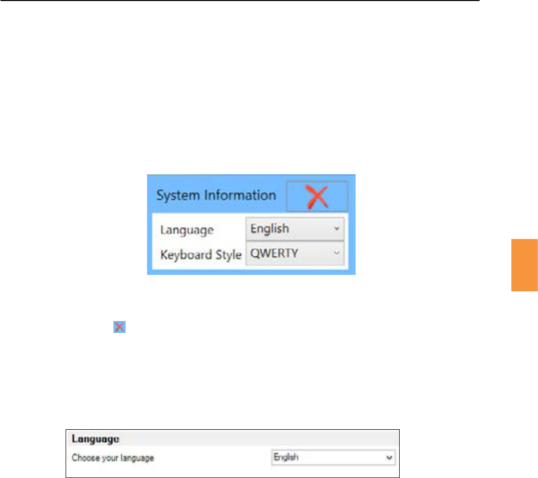
Aerunlockingthesysteminformaonscreen,navigatetotheLanguageandKeyboardsengs.From
there the language on-screen and keyboard style can be changed using a drop-down menu. If the
selected item in either drop down menu is changed, then clicking the will save these changes
and modify the language and keyboard.
1. Click
2. Unlockthesengs.
3. Select your required language from the drop down list.
Inthe workareatheSystem Informaon Panelcontainsa buon
which launches the dialog.
Withinthekeyboardshortcutconguraondialog,eachavailablecommandislistedfollowedbyan
inputboxandclearbuon(withacross).
Toassignakeyboardshortcuttoacommand,clickinthecorrespondingtext/inputboxandthenhold
down the keys you want to assign to this command. The input boxwill change from “PleaseEnter
ShortcutKey”toalistofthecurrentlyhelddownkeyboardkeysseparatedby+s.Oncethekeyboard
keysarereleasedthosekeysaresavedtotheinputbox.
Pressing the buonwillremovethekeyboardshortcutforthatcommand.
In order to save these changes you must press the buonattheboomofthedialog.
Intheworkarea,oncetheshortcutsaresetup,simplypresstheshortcutkeystoacvatethecommand.
Figure 5-29 RI Witness™ Manager Language Seng
Figure 5-28 Language selecon
4. Select your required keyboard style from the dropdown list.
5. Click the to save and close the window.
The language used can also be changed from RI Witness™ Manager
1. Click
2. ChooseyourrequiredlanguagefromthedropdownlistintheLanguagesecon
Secon 5
RI Witness™ Basic Operaon
39
5
List of commands:
• Fire / Enter Laser Mode.
◦Enters laser control mode.
◦ Ifalreadyinlasercontrolmodethiscommandresthelaser.
• Preset Laser Down.
• Preset Laser Up.
• Start / Stop Recording.
• Take Picture.
• Zoom In / Zoom Out.
◦Zooms out fully if already zoomed in.
◦If zoomed out zooms into pre-set zoom value at centre.
• Zoom In.
◦Zooms into centre one step.
• Zoom Out.
◦Zooms out from centre one step.
• Freeze Frame.
Shortcut keys should be limited to the funcon keys to avoid conicts with typing or
barcodes.
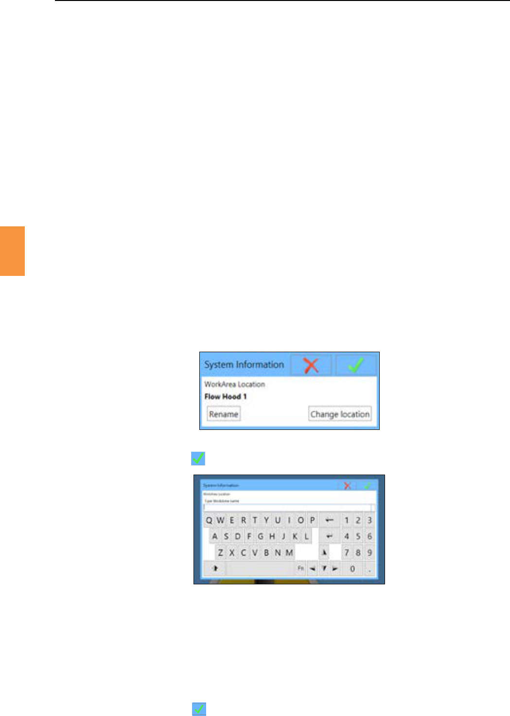
1. Log in as an Admin user.
2. Click
3. Click
4. Type the name of the work area using the on screen keyboard.
5. Click the Icon.
Figure 5-30
Figure 5-31
1. Log in as an Admin user.
2. Click .
3. Click .
4. Click
5. Choosethelocaonrequiredfromthelistorclicktosetanotherlocaonname.
6. Click the Icon to accept the change.
Secon 5
RI Witness™ Basic Operaon
5
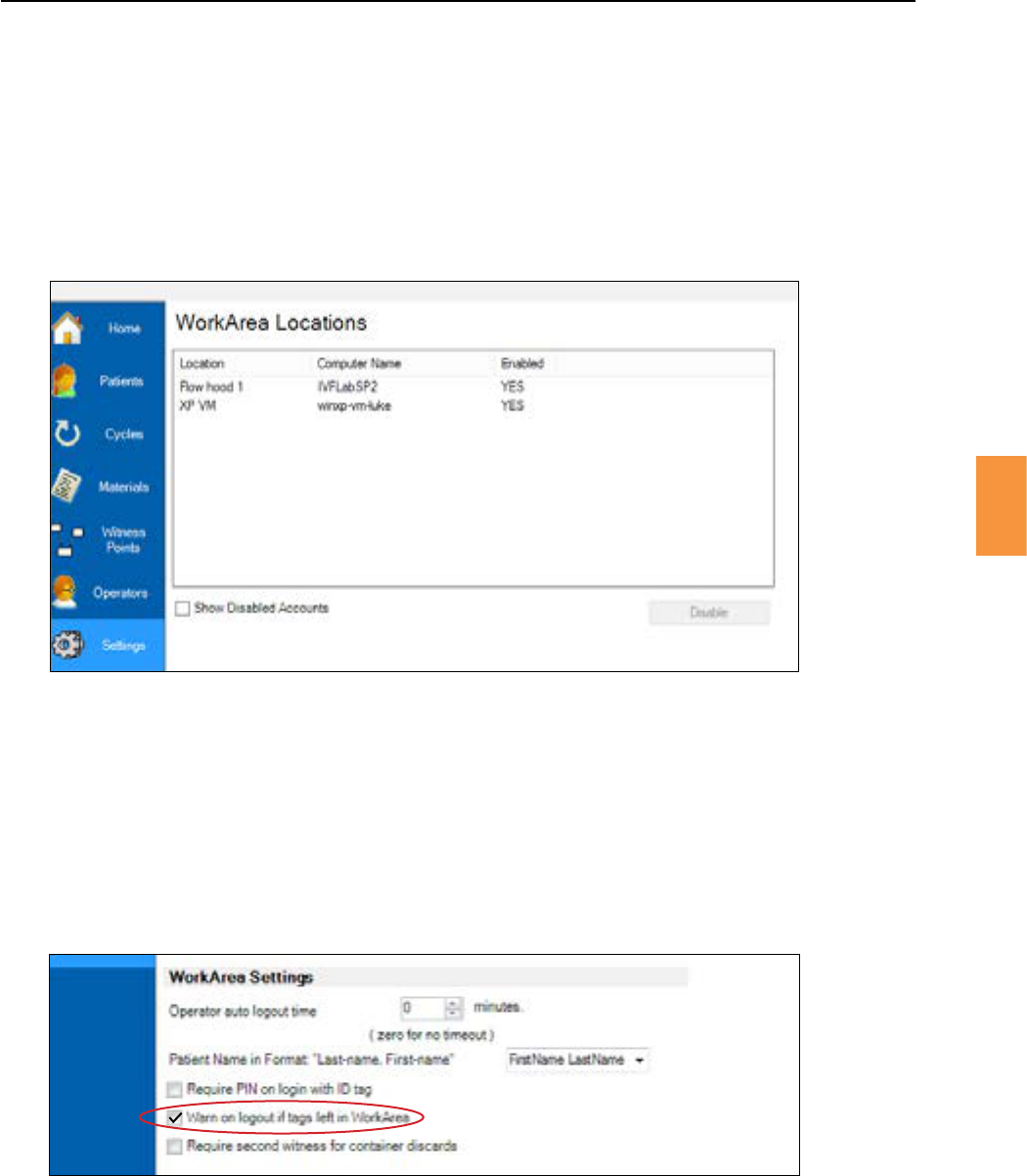
1. Open RI Witness™ Manager.
2. Click .
3. Click ,youwillnowseeallnamedworkarealocaons.
4. Highlight the work area and click .
5. Disabledaccountscanbeviewedbycking
Tohelpavoidmismatchesbeingrecorded–“CardLeinReader”.
1. Open RI Witness™ manager.
2. Click .
3. Click .
4. Underworkareasengsck
Figure 5-32
Figure 5-33
Secon 5
RI Witness™ Basic Operaon
5
Figure 5-34
Secon 6
RI Witness™ Manager
6
RI Witness™ Manager can be used on PCs or tablets outside of the RI Witness™ work areas, predominately
foradministraonpurposes.
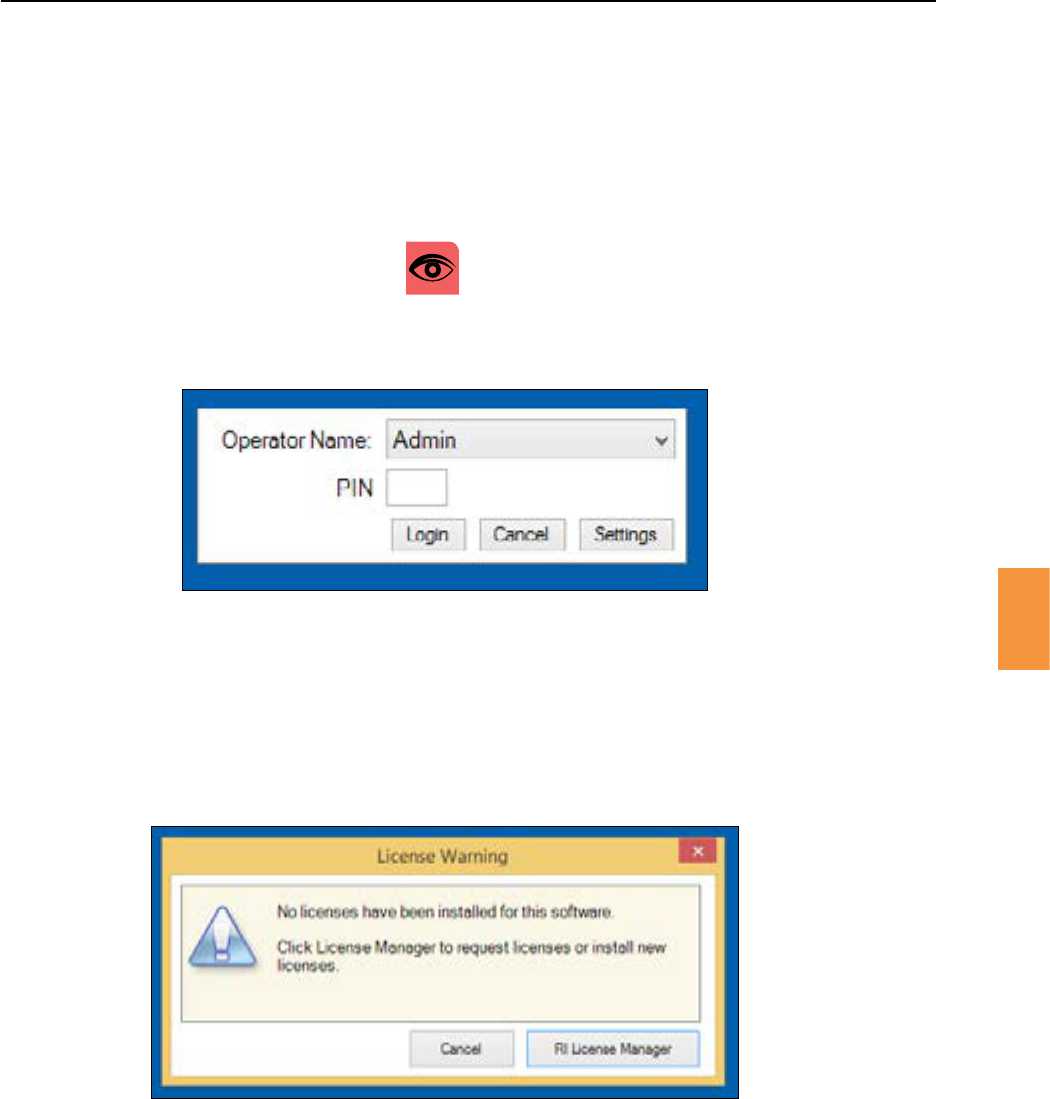
1. Double click the desktop icon.
2. Choose your assigned operator name from the list.
3. Enter your 4 digit PIN.
4. Click
Figure 6-1 Logging in
Figure 6-2 License warning
RI Witness™, Traceability, Data Capture, Cryo and Imaging must be licensed.
LicensinginformaonisstoredinthesharedRIWitness™database.
On each subsequent use of RI Witness™ Manager, a license check is made and a similar license warning
windowwillinformtheoperatorifanylicensesareclosetoexpiraon.
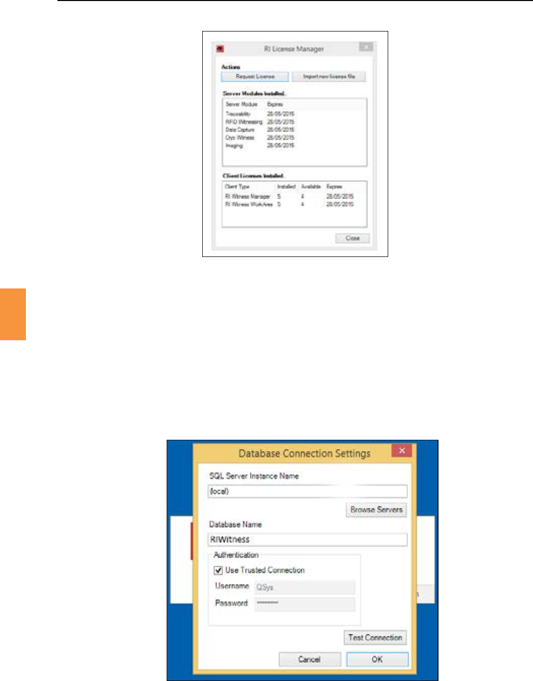
Atanyme,theRILicenseManagermayalsobeinvokedasaseparateapplicaonbyclicking
and then RI License Manager.
Secon 6
RI Witness™ Manager
6
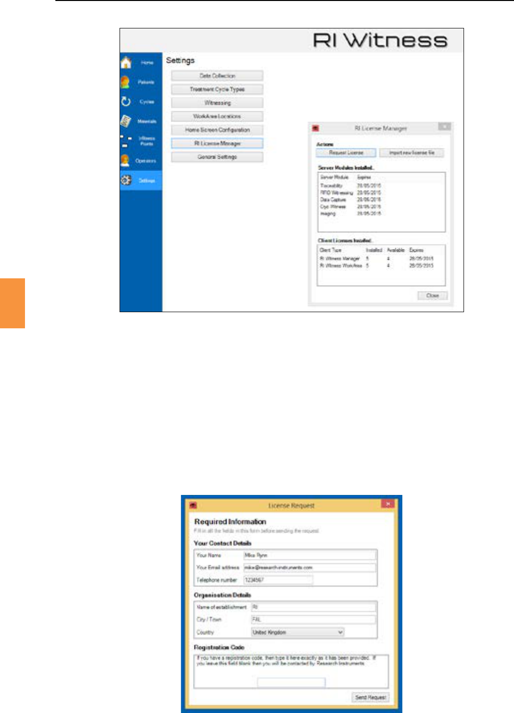
Figure 6-3 RI License Manager
Ifyourlicenseisclosetoexpiraon,youcanquicklyrenewyourlicense.
1. Click in the RI Witness™ Manager license warning window. A license request
form will open. See Figure 6-4.
2. Complete the details on the form.
3. IfyouhaveaRegistraonCodeissuedbyRI,enteritattheboomoftheform.
4. Click aercomplengalltheelds.
5. If internet access is available, a response will be returned by the RI Licensing Server. See Figure
6-5.
Figure 6-4 The license request form
Secon 6
RI Witness™ Manager
6
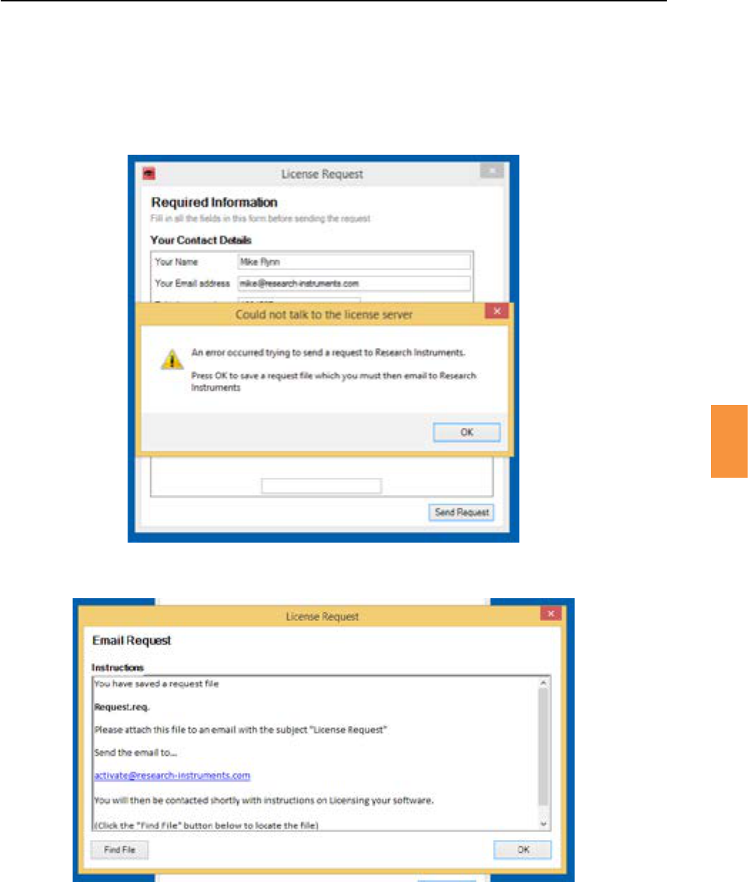
6. Ifinternetaccessisnotavailable,pleasefollowthedisplayedinstruconstosavealicense
requestle.TheleshouldthenbeemailedtoRIatacvate@research-instruments.com.
7. OnceRIhasreceivedyourrequest,aLicenseDatalewillbeemailedbyreturn.
Figure 6-5 A response from the RI license server
Figure 6-6 The license request email
8. TheLicenseDataleshouldbemadeavailabletotheRIWitness™ManagerPCwherelicensing
is performed.
9. EachmeRIWitness™Managerisopenedfollowinglicenserequest,LicenseManagerwindow
will be displayed. See Figure 6-7.
10. OnreceiptoftheLicenseDatale,clickin the license manager
dialoguebox.Browsetotheemailedlicensedataleandselect.TheLicenseManagerwillnow
be updated with the new license details.
Secon 6
RI Witness™ Manager
6
Figure 6-7 The License Manager window
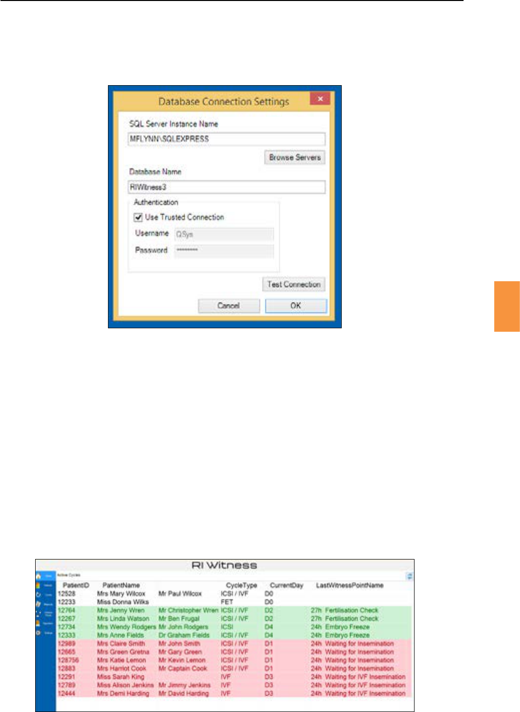
RI Witness™ Manager must connect to the shared RI Witness™ database.
1. AtRIWitness™Managerlogin,adatabaseconneconswindowwillbeshownifaconnecon
cannot be made. See Figure 6-8.
Figure 6-8 The RI Witness™ database connecon is unavailable
Secon 6
RI Witness™ Manager
6
2. Click the pagebuontoshowthedatabaseconneconsengswindowand
entertheappropriateservername,databasenameandauthencaondetails.SeeFigure6-9.
See the IT Requirements Manual for more details on database management.
Aerlogin,aninialscreenshowsanumberofmainmenubuons.Themainmenubuonspresented
will depend on operator group membership (administrator, normal) and the mixture of installed
products (RI Witness™, Traceability, Data Capture, Imaging and Cryo).
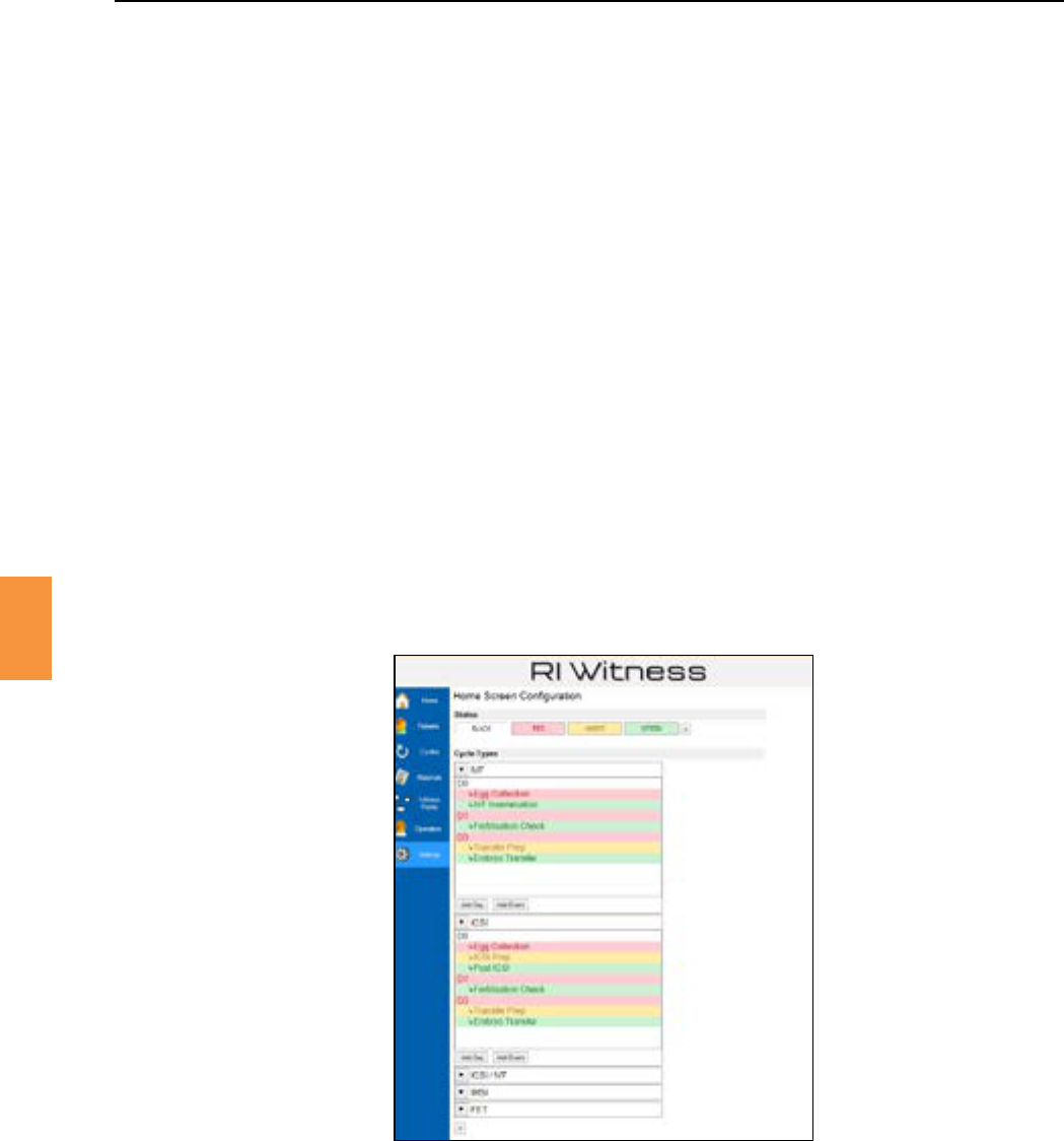
When rst logging into RI Witness™ Manager the Cycles Overview Board is displayed. Clicking the
buononthelehandtoolbarwillreturntheusertotheHomescreen.Thebuonon
theHomescreencausesthedisplaytorefreshbyre-queryingthedatabasetondtheacvetreatment
cycles.
1. Toseethecycledetailsofapaent,doubleclickontherowwiththepaent’sdetails.A
page will open.
Figure 6-9 Database connecon sengs
Figure 6-10 Home screen
Secon 6
RI Witness™ Manager
6
Eachdayofacycleoraneventcanbegivenadierentcolourcodetoaideasyandquickidencaon
of the cycle status. This can also assist the ordering of procedures.
TocongurethecolourcodingwithintheHomescreen,followthestepsbelow.ExactspellingsofCycle
Types and Events used in the Witness Point Diagram must be used.
1. Click
2. Click
3. Firstlyyouwillneedtosetup“States”.Thesecanbedaysoreventsandarecolourcoded.
YoucouldsimplydoDay1,2,3,4,5tostartwith.
4. Click +withintheStateseld.
5. Type the name of the State, eg Embryo Freeze, Day 0, Day 1, etc.
6. Onclickingthebackgroundorforeground(TextColour)box,acolourpickerwillappear.Select
the desired colours.
7. Press
8. Nextaddacycletype.Clickthe + buonwithintheCycletypeseld.ACycleTypeboxwill
appear. Type in the cycle type carefully, ensuring there are no spelling mistakes. The cycle type
willneedtomatchwhatyouhavealreadysetwithintheTreatmentCycleTypeseldswithinthe
database(See“CycleTypes”onpage70.)AnexampleofacycletypecouldbeIVF,ICSI/IVF,
FET, ICSI, etc.
Figure 6-11 Home screen
9. Click .
10. Select the drop down arrow you would like to colour code.
11. Click or
12. Assign a day number, ie 3 for Day 3.
13. WithintheMessageeld,typetheDaydescripon,ieDay3.
14. IntheStatedropdowneld,choseoneoftheStatesthathasbeensetup.
15.
16. Repeat for each Cycle Type.
Secon 6
RI Witness™ Manager
6
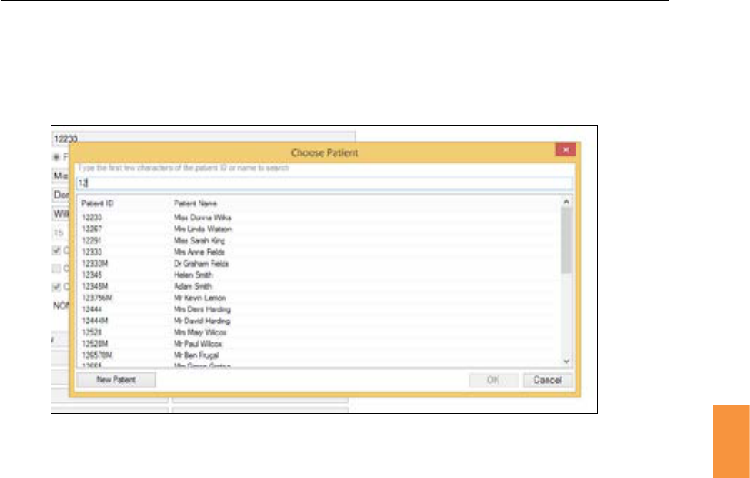
Click the buontoshowthewindowifnopaenthasbeenselectedortoview
detailsofaselectedpaent.
1. TypetherstfewcharactersofanameorpaentIDtobrowseaseleconofmatchingpaents.
2. Highlighttherequiredpaentandclickordoubleclicktherequiredpaenttoviewtheir
details.
3. Treatmentcycles,witnesspointsandtagsfortheselectedpaentcanalsobeviewedby
selecngthetabsinthisscreen.
4. ClinicswithCryoenabled,canprintbarcodesfortheselectedpaentbyclicking
. Barcodes printed from here will be recognised by the RI Witness™ system as belonging
totheselectedpaent.
5. Click tocreateadhesivesheetswiththeselectedpaentdetails.Thesecanbe
aachedtoplascwareforthispaent’ssamples.Forfurtherdetailsregardinglabelprinngsee
“PrinngPaentLabels”onpage54.
1. Click thebuontoshowthewindow.
2. Click on buon.
3. Enterdetailsintoappropriateelds–alleldswhichhavebeeneditedarehighlightedinpink.
4. Save all changes.
FromthePaentspagethereisalsoanopontoaddorchooseanewpaent.
A paent cannot be assigned to a partner unl the partner has also been entered into the
RIWitness™Managersowareseparately–See“AssigningPartners”onpage50.
Label sheets and barcodes can be printed from this page.
Figure 6-12 Choose paent screen
Secon 6
RI Witness™ Manager
6
Figure 6-13 New paent details
OpenPaentdetailsasoutlinedabove.
1. Click the buon to change to the editable window.
2. Click the buontosavechanges.
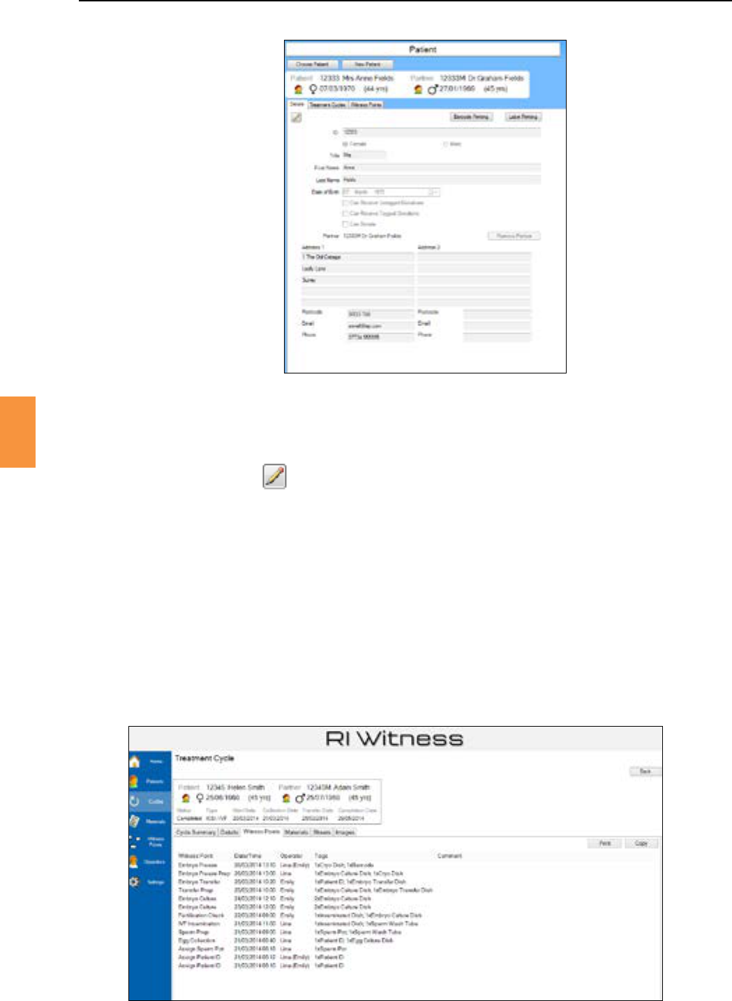
1. FromthePaentspage,selectthe tab to view all previous cycles undertaken
forapaentorcouple.
2. Select the tab to view all witness points registered in an open cycle.
3. Select the tabtoseealllocaonsthattagsassignedtothepaenthavebeenseenbyRI
Witness™.
RefertoFrequentlyAskedQuesonsifnecessary.
Figure 6-14 Looking up paent histories
Secon 6
50
RI Witness™ Manager
6
Figure 6-16 Assign Partners
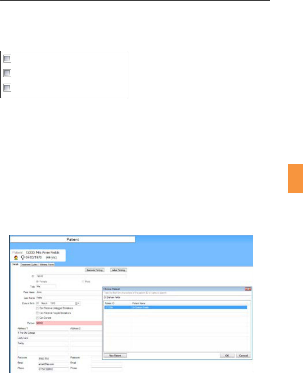
1. Createanewpaententry,orchooseexisngpaent,leavingthepartnereldblank.
2. Createanewpaentforpartner.
3. Tolinkthe2paents,selectthebuontoshowtheChoosePaentwindow.
4. LocatepartnerbytypingtherstfewcharactersofanameorpaentIDinthesearchwindowto
browseaseleconofmatchingpaents.
5. Clickonthepaentnameandthenconrmseleconbyclicking. See Figure 6-16.
InthePaentdetailswindowselectrelevantdonoropons.
Can Receive Untagged Donations
Can Receive Tagged Donations
Can Donate
Figure 6-15 Assign Donor Status
Theavailability of the donatecheckboxes will dependonthegenderof the paent,ie only female
paentscanreceivedonaons.
Secon 6
RI Witness™ Manager
51
6
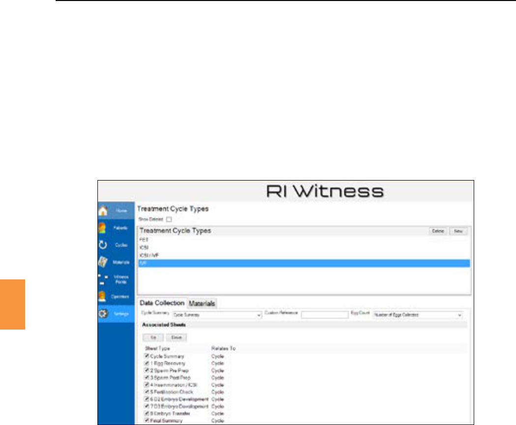
Acyclerelatestoaspeciccourseoftreatment(IVF,ICSI,IUI,etc).
Only“administrator”operatorsmaycreatecycletypes.
1. Click the mainmenubuonandthenclick to view all treatment cycle
types. See Figure 6-17.
2. Click to add each cycle type.
3. Use a right click to a cycle type.
Traceability operators may specify the range of materials that are used in a cycle type. Data Capture
operators may specify the data sheets that are used in a cycle type.
Figure 6-17 The Treatment Cycle Types Window
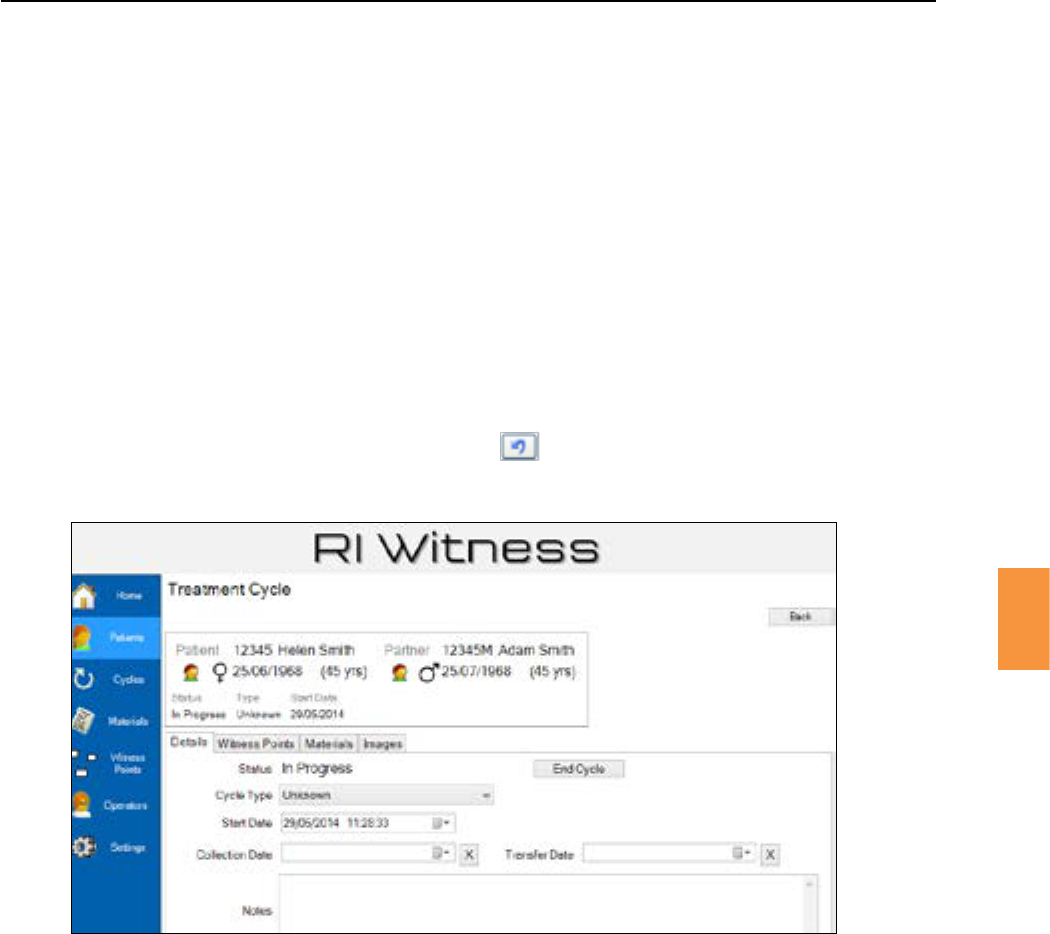
1. Click the mainmenubuonandselectapaentbyenteringanameorpaentID.
2. Click the tabtoshowthelistoftreatmentcyclesforthispaent.Fora
newpaentthislistwillbeempty.
3. On the tabofthepaentscreenclick to create a new
cycle.Thenewcycleisshownwithastatusof“InProgress”andacycletypeof“Unknown”.See
Figure 6-18.
4. Traceability operators may click the tab to view a list of material batches related to
this cycle.
5. All operators may click the tab to view a list of witness points performed during
this cycle.
Select a cycle type from the pulldown list.
Secon 6
52
RI Witness™ Manager
6
Figure 6-18 Starng a new cycle.
1. Click fromthePaentswindow.
2. Select a Cycle Type from the pulldown on the window.
IfEggCollecon/EmbryoTransferdatesareenteredonthe tab of a treatment cycle then these
events will be available from the work area touchbuon.
See“PerformingAProcedureinRIWitness™”onpage28formoredetailsofpaentseleconusing
.
Anewlycreatedcyclewillbeassignedthestatus“InProgress”.Whenthepaenttreatmenthasbeen
completed click tochangethestatusto“Completed”.
An administrator operator may click the buonofa“Completed”cycletoreturn
thestatusto“InProgress”.
Secon 6
RI Witness™ Manager
53
6
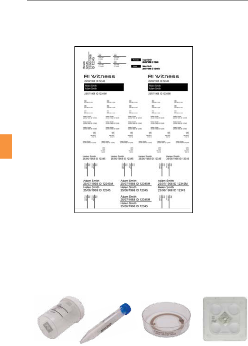
LaserprintableadhesivepaentidentylabelsareavailablefromRI.
Thesheetprovidesarangeoflabelsizeswithaseleconofnormalandreverseprinng.SeeFigure
6-19.
Figure 6-19 RI laser printable label sheet.
Reverse printed labels are viewable through the base of containers.
Label categories such as “Petri Dish” and “Test Tube” are for guidance only. Please select a label
appropriatetoyourplascware.
“Testtube”labelsmaybeusedtoholdarectangularRFIDtaginposionalongthelengthofatube.
Thereverseprinted“4welldish”labelandthesquareRFIDtagaretherecommendedchoicefora4
well dish. See Figure 6-20.
RILabelsareanoponalcomponentofRIWitness™.
Figure 6-20 Posioning of paent identy labels
Secon 6
RI Witness™ Manager
6
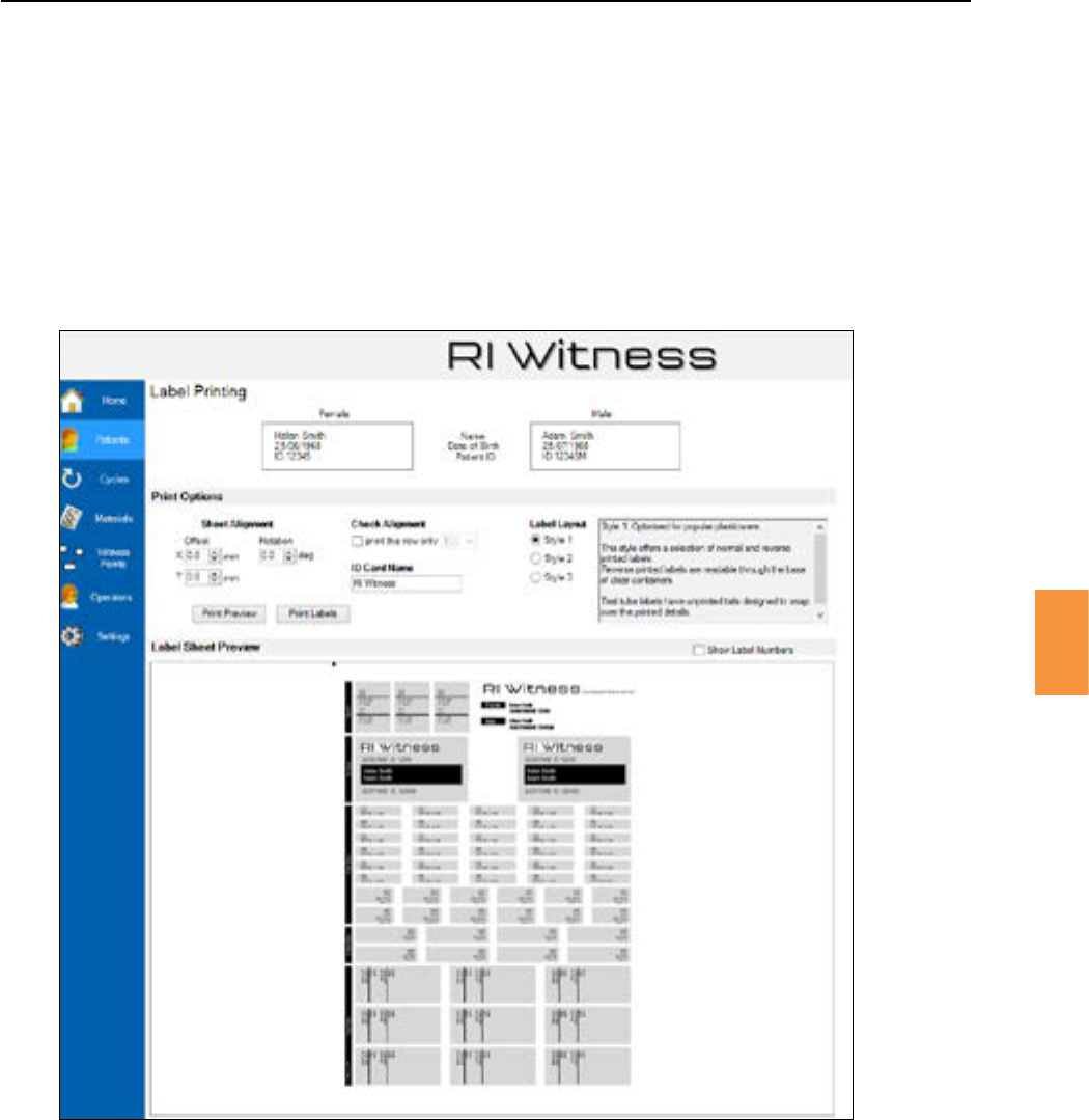
1. FromthepaentdetailswindowclickSee Figure 6-21.
2. Load a blank label sheet into a laser printer. For repeatability of alignment use a manual feed
path and take care when placing each sheet.
3. Setall“SheetAlignment”valuestozeroandclick.
4. Checktheprintedsheet.Measuretheosetsrequiredtocorrectlyposiontheprinteddetails
withinalabelboundary.Payparcularaenontovercalposioningwithinthesmallestlabel.
See Figure 6-22.
Figure 6-21 The label prinng manager
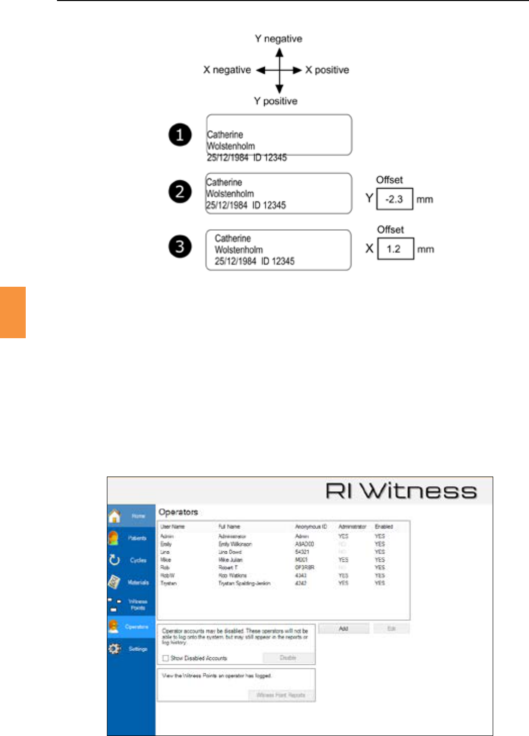
TheexampleshowninFigure6-22showsdetailsofanalignmentcorreconwithintheboundaryofthe
smallest label.
5. Therstprintshowsincorrectalignment.
6. VercalalignmentiscorrectedbyanegaveYoset.
7. HorizontalalignmentiscorrectedbyaposiveXoset.
Secon 6
RI Witness™ Manager
55
6
Figure 6-22 Label text alignment
UsetheLabelLayoutbuonstoselectanappropriatestyle.
Style1isopmisedforpopularplascware,Style2maximisestheuseofavailablespaceandStyle3is
amixtureofStyles1and2.
Arotaonalignmentcorreconisrarelyrequired.
Check and select a row number to print a single row of the smallest labels
only. This may be useful if reusing a sheet during the alignment process.
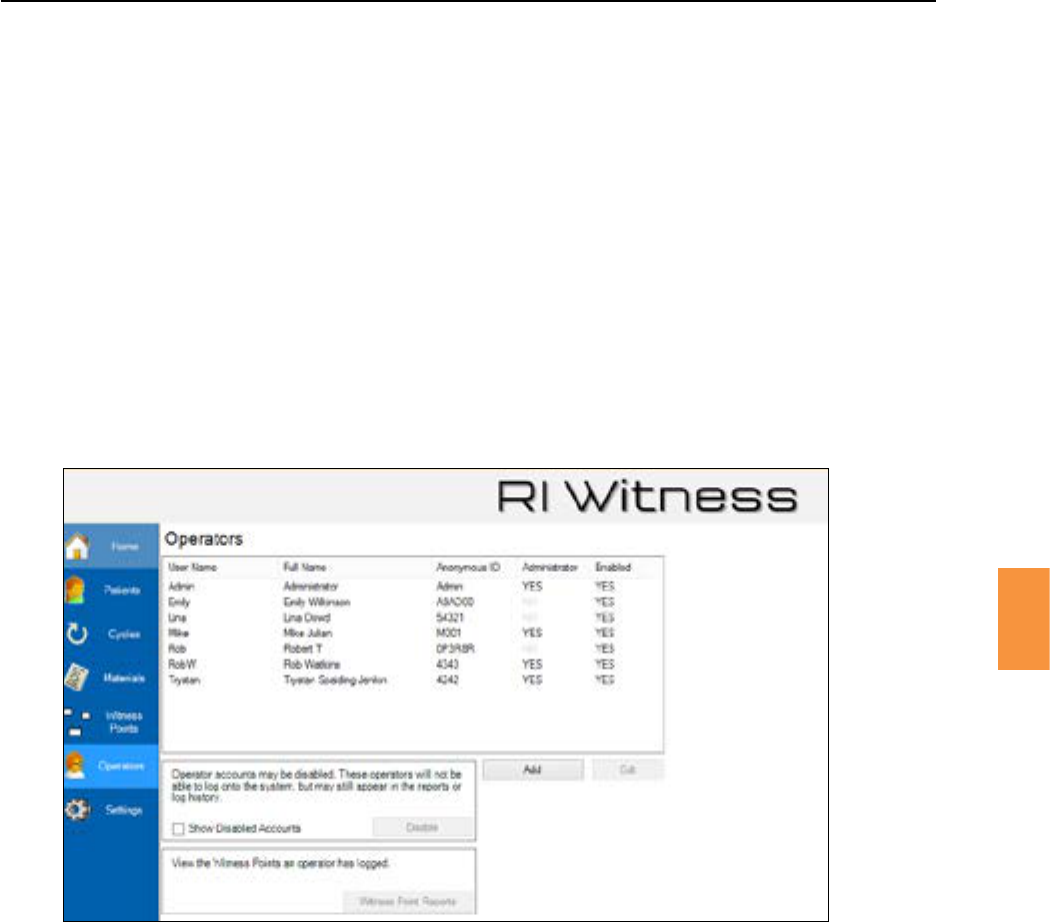
Click to display a list of all enabled operators. See Figure 6-23.
Figure 6-23 Operator management
Secon 6
56
RI Witness™ Manager
6
1. Click to specify details for a new operator. See Figure 6-24.
2. Select an operator and click to change operator details.
An operator must have a Username, Full Name and Anonymous ID. The Anonymous ID is used for
printed reports.
Groupmembershipisspeciedas“normal”or“administrator”.
Some RI Witness™ features are only available to an “administrator” operator. Administrator only
features include the use of admin assign and making changes to the witness point diagram.
Figure 6-24 Operator Details
Only enabled operators may log in. Click to remove an operator from the enabled list. Check
“ShowDisabledAccounts”toviewalloperators.
The operator PIN must be a sequence of 4 numbers.
Click the mainmenubuonthenclick to specify the Name of Clinic that will
appear in all printed reports. SeeFigure 6-25.
Secon 6
RI Witness™ Manager
57
6
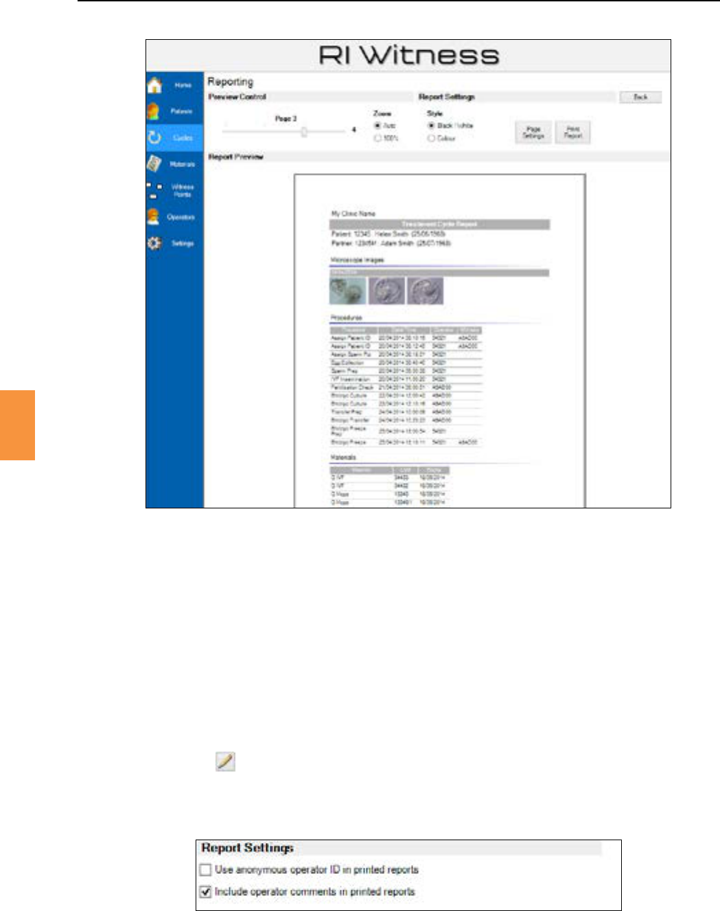
Figure 6-25 The heading of a printed report will show “My Clinic Name” as specied by “Name of Clinic” on the
general sengs page.
Userscanaddextracommentstofurtherexplainanymismatchesinthehistory
1. Open RI Witness™ Manager.
2. Click the buon.
3. From double click the cycle required to view. This can be seen by clicking
paentsalso.
4. Click the tab.
5. Double click the witness point.
6. Click the icon.
7. Enteraddionalcomments.
8. Click
Figure 6-26 Report sengs
Secon 6
58
RI Witness™ Manager
6
ThewitnesspointsthatarepresentedtoallworkareaoperatorsaredenedinRIWitness™Manager
by a witness point diagram.
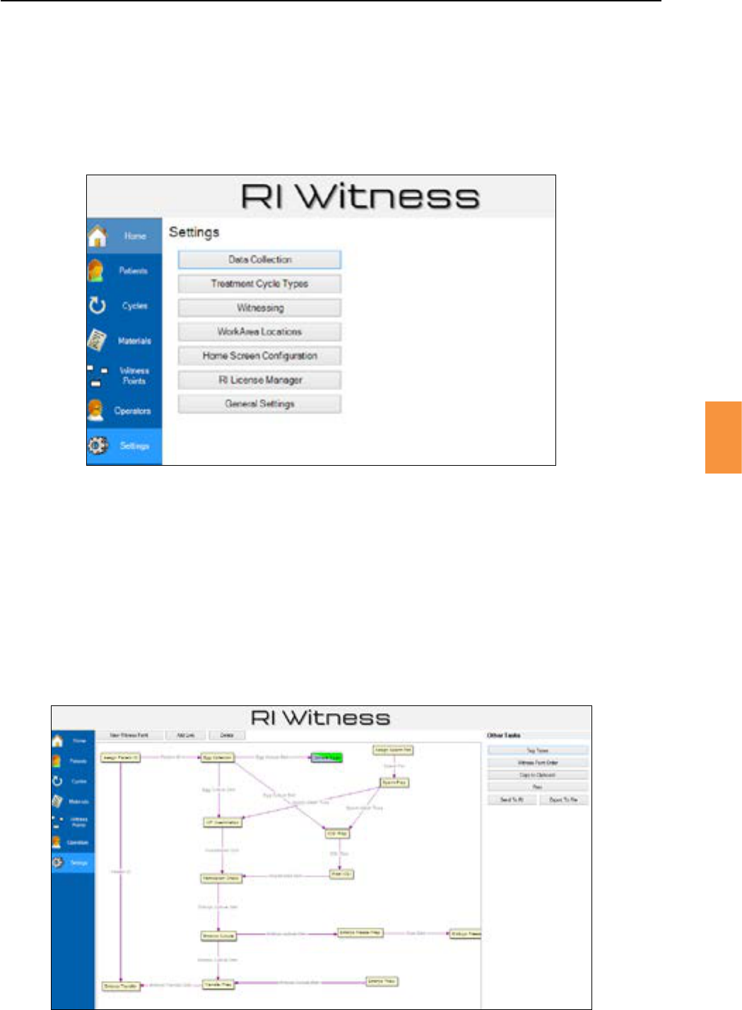
To view the witness point diagram click the mainmenubuonandthenclick. See
Figure 6-27 and Figure 6-28.
Figure 6-27 The sengs screen
Click “Witnessing” to view the witness point diagram
To add a new witness point, click and then click anywhere in the diagram. Enter a
nameforthewitnesspoint,eg“IVFInseminaon”
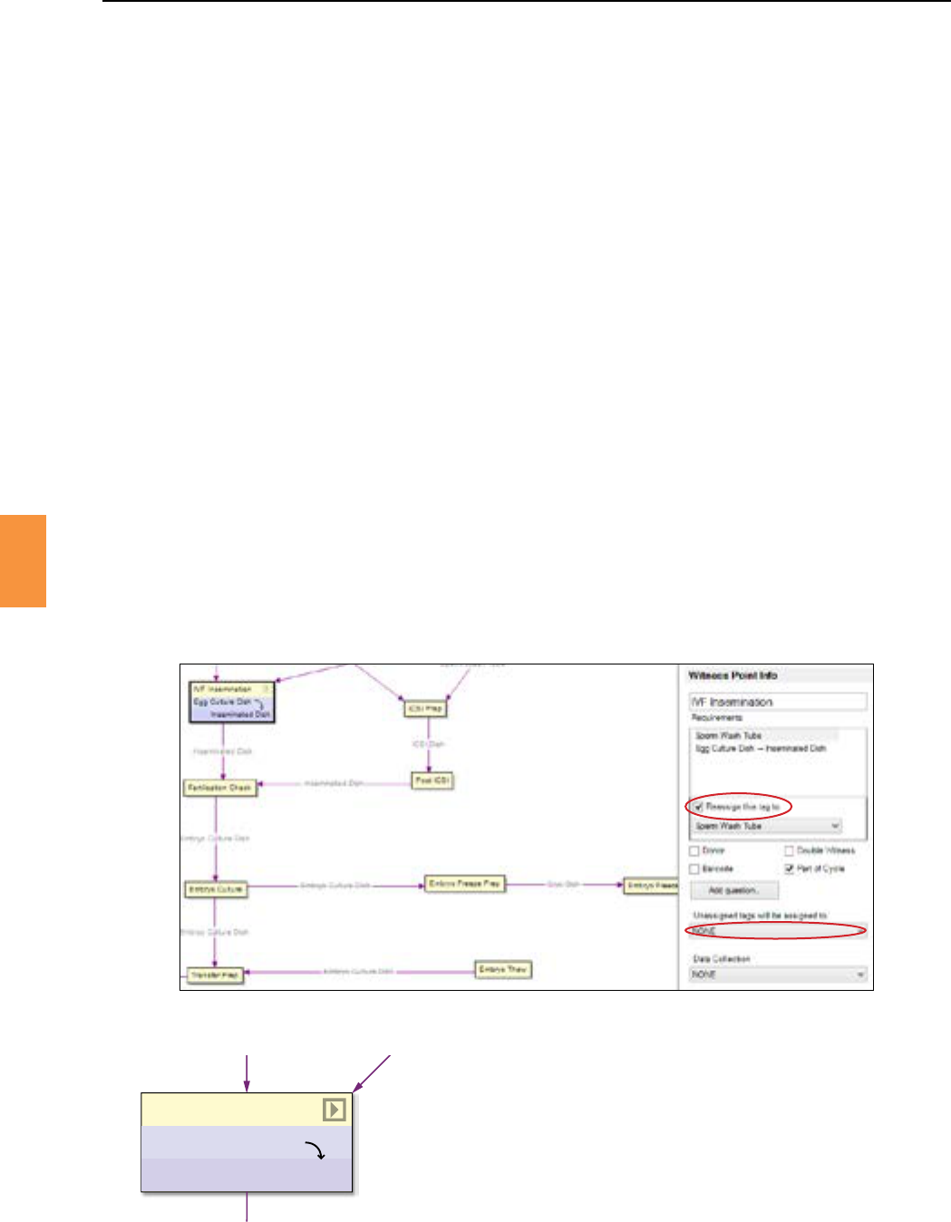
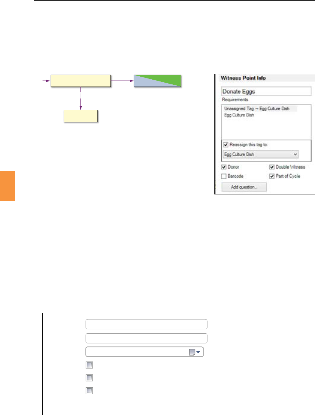
UsetheWitnessPointInfopaneltospecifytheaributesofawitnesspoint.Witnesspointaributes,
egreassignan“eggculturedish”tagtobecomean“inseminateddish”tag,aredescribedbelow.
Tagnamessuchas“inseminateddish”mustbedenedbeforetheymaybereferencedbyawitness
point.See“TagTypes”onpage63.
Figure 6-28 The witness point diagram.
Secon 6
RI Witness™ Manager
59
6
Figure 6-29 Detailed informaon for the “IVF Inseminaon” witness point
Thelinks(arrows)betweenwitnesspointboxesrepresenttags(dishes,testtubes,etc)thatarethe
requiredinputsandproducedoutputsoftheproceduredenedbythatwitnesspoint.
To create a link, click and then drag between two witness points.
Awitnesspointmayrepresentthereassignment(transformaon)ofonetagtypeintoanother,egan
“EggCultureDish”becomesan“InseminatedDish”asthespermisintroduced.
A reassignment is illustrated in Figure 6-29 where the checkboxischeckedtospecify
thattheselectedtagtype“EggCultureDish”willbereassignedasan“InseminatedDish”whenthis
witnesspointisexercisedbytheworkareaoperator.
Witness points may require that unassigned (empty, unused) tags be introduced into the work area.
The“IVFInseminaon”WitnessPointdoesnotrequireanunassignedtagasthe“Unassigned
tagswillbeassignedto:”pulldowninFigure6-29shows“none”.
Whereawitnesspointrequirestheintroduconofanunassignedtag,usethe“Unassignedtagswillbe
assignedto:”pulldowntoselectthetargettagtype.
Paent ID (female)
IVF Inseminaon
Egg Culture Dish
Inseminated Dish
Figure 6-30 A reassigned tag is represented by a curved line between
the two tag names
Anunassignedtagisrepresentedbyastraightlinebetweenaquesonmarkandthetargettagname.
A witness point may specify both a reassignment and the use of an unassigned tag.
Secon 6
60
RI Witness™ Manager
6
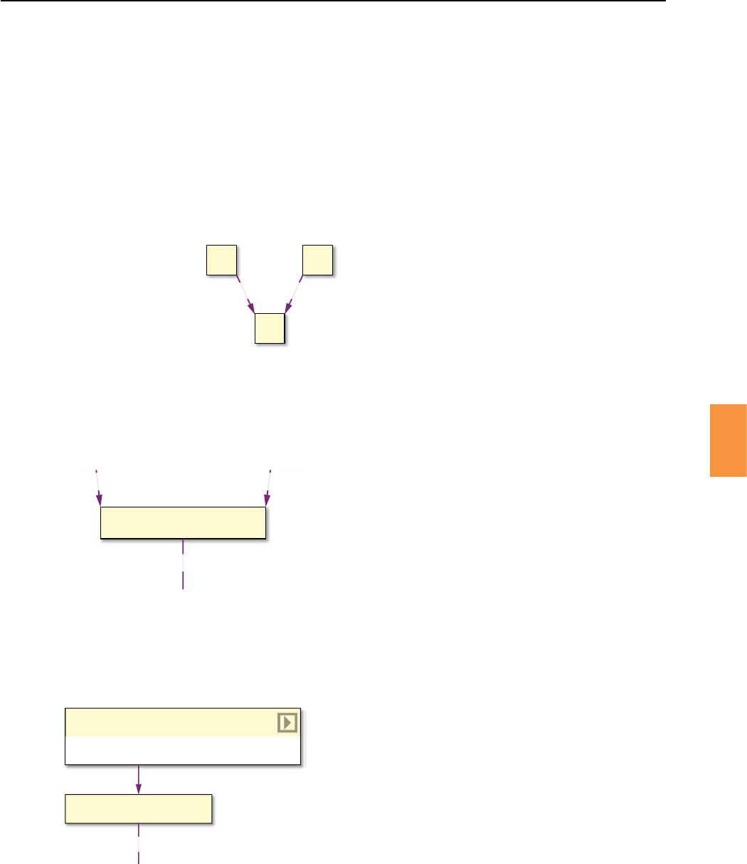
Incoming links to a witness point specify the tags that must be present before the procedure represented
bythewitnesspointcanbeperformed.Ifanunassignedtagisspeciedthenthatcontainermustalso
be present before the procedure can be performed.
Awitnesspointwithmulpleinputlinksofthesametagtypeeg“dishX”,representsanORoperaon,
ie the required container may be sourced from the procedure represented by witness point A OR B.
A B
C
Dish X Dish X Figure 6-31 Dish X must be available to
witness point C
Witness point A OR B may be the source
AwitnesspointwithmulpleinputlinksofdieringtagtypesrepresentsanANDoperaon,iethistag
type AND that tag type are required to perform the procedure represented by this witness point. See
Figure 6-32.
A B
IVF Inseminaon
Sperm Wash Tube Egg Culture Dish
Inseminated Dish
Figure 6-32 The “IVF Inseminaon” witness point
represents a procedure that requires a “Sperm
Wash Tube” AND a “Egg Culture Dish”
Entry(inial,starng)witnesspointshavenoincominglinks.Anentrywitnesspointwillalwaysrequire
anunassignedtagwhichwillbecomeassignedoncompleon.SeeFigure6-33.
Figure 6-33 “Assign Paent ID (female)” is an
entry witness point as it has no input links
An unassigned tag (here an unassigned ID card )
is required
Assign Egg Wash
Egg Wash Dish
Paent ID (female)
Assign Paent ID (female)
? → Paent ID (female)
Checking the box,seeFigure6-29,changesthecompleonsequenceforawitness
point. A second operator must log in to approve the procedure. Entry witness points are generally
double witness points.
Secon 6
RI Witness™ Manager
61
6
Amismatchalarmwillbegeneratediftagsassignedtopaentswhoarenotspeciedaspartnersare
introduced to the work area.
Theexcepontothisruleisprovidedbydonorwitnesspoints.Checkingtheboxwillcreatea
donor witness point which is given a diagonal colouring. See Figure 6-34.
Assign Egg Wash
Egg Wash Dish
Egg Prep
Donate Eggs
Figure 6-34 A known donor witness point
Anincominglinktoadonorwitnesspointspeciesataggeddonaonandcoversproceduressuchas
egg/embryodonaon/sharingaswellassurrogacy.
Whenthewitnesspointisselectedtheoperatorchoosesthedonaonrecipient.Therecipientidenty
isassignedtothetagcontainingthedonatedmaterial.Theworkareanowcontainstagswithamixture
ofdonorandrecipientidenes.Thisdoesnottriggeramismatchbecausethetagshavethedonor
witness point in common.
TaggedDonaonsrequirethatthedonorandrecipientbespeciedassuchviathe and
checkboxesavailableinthepaentdetails.SeeFigure6-35.
Can Receive Untagged Donations
Can Receive Tagged Donations
Can Donate
First Name
Last Name
Date of Birth
Wendy
Rogers
27 October 1967
Partner 36734M Mr John Rodgers
Figure 6-35
The checkbox species
theabilitytomakeataggeddonaon.
The
checkbox must be checked for the
recipient.
The donor witness point ensures
that donated tagged material is only
available to paents that have the
box
checkedintheirpaentdetails.
Secon 6
62
RI Witness™ Manager
6
Spermdonaonsareusuallyuntagged.
An donor point will be an entry witness point for a female recipient of donated sperm. The donated
sperm will be transferred to an unassigned tag that is then assigned to the female recipient when the
donor witness point is selected.
Thedonorwitnesspointensuresthatuntaggedspermisonlyavailabletopaentsthathavethe
boxcheckedintheirpaentdetails.
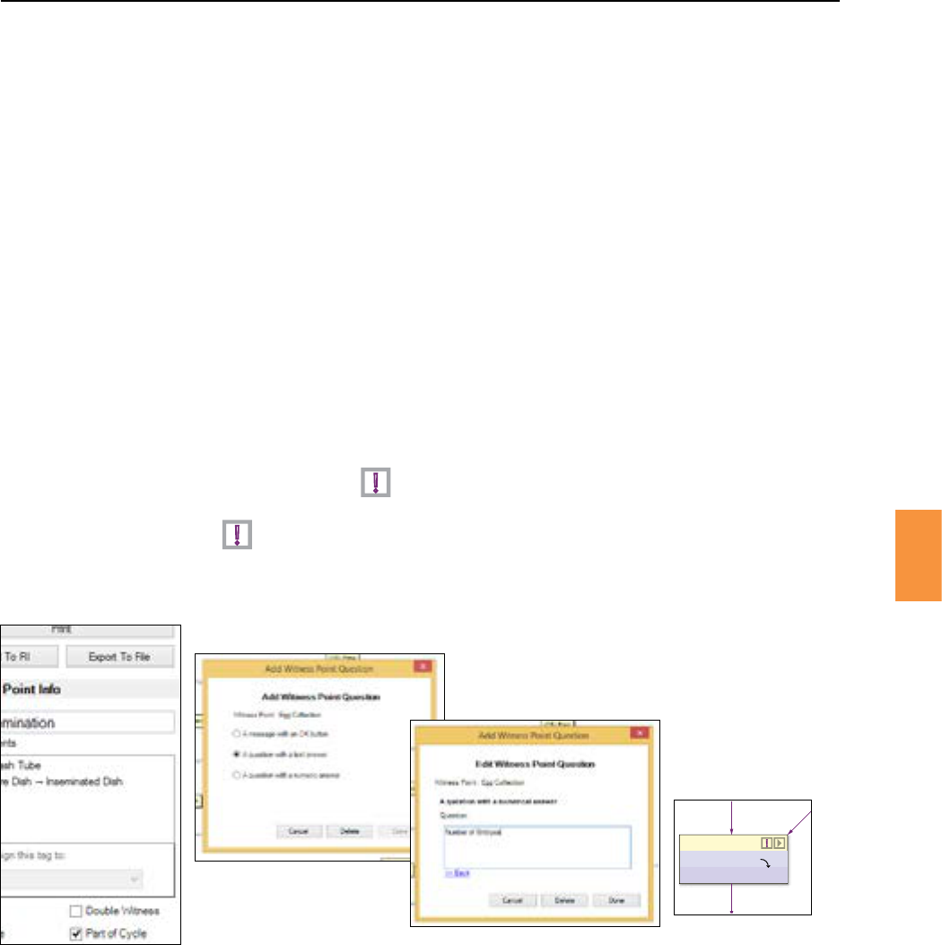
Aquesonmaybepresentedtoaworkareaoperator.Thequesonandresponsewillberecordedin
the history log.
Tosetaquesonfortheselectedwitnesspoint:
1. Click the buon.
2. Chooseaquesontypeandenterthequesontext.SeeFigure6-36.
3. The diagram will show an appendedtothewitnesspointnameifaqueson
has been added.
4. Click the toeditthequesondetails.
Figure 6-36 Adding a witness point queson that requires a numerical answer
Note the exclamaon aer the witness point name
Paent ID (female)
IVF Inseminaon
Egg Culture Dish
Inseminated Dish
!
!
!
Secon 6
RI Witness™ Manager
63
6
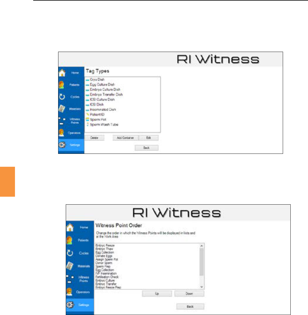
Click to specify the name and icon for each RFID tagged item used in the witness point
diagram. See Figure 6-37
Figure 6-37 Tag types
From the witness point diagram page click to specify the order in which points will
be displayed to the work area operator. Click or to change the order. See Figure 6-38.
Figure 6-38 Seng the witness point order.
Workareaevents,egwitnesspointseleconandtagmismatches,areloggedintheshareddatabase.
Thewitnesspointlog maybeexplored in detailor viewed as a summary. A printedreport maybe
generated from any view of the witness point log.
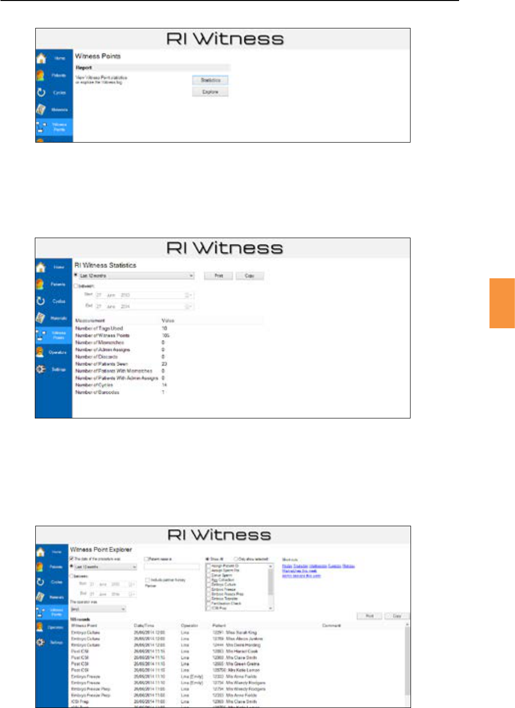
Click the mainmenubuonthenclick or to view the witness point
log. See Figure 6-39.
Secon 6
RI Witness™ Manager
6
Figure 6-39 The witness points screen
Click stascs or explore to view the witness point log
TheWitnessPointExplorershowseventsfromthewitnesspointlog.
Theviewmaybelteredbydate,operator,paentandtagtype.Shortcutlinksareprovidedforcommon
lters,eg“Monday”,“Adminassignsthisweek”.SeeFigure6-40.
Figure 6-40 Exploring the witness point log
Thestascsviewsummarisesthewitnesspointlogbypresenngsignicanttotals,eg“Tagsused”,
“Paentsseen”,etc.Theviewmaybelteredbydate.SeeFigure6-41.
Figure 6-41 Stascs from the witness point log
Secon 7
Cryo Witnessing
65
7
Many embryology labs wish to extend witnessing and reporng to include samples stored in cryo
storage.TheCryofeatureisabarcodelabellingsoluonforcryostraws.
Clinicshavetheoponofscanningbarcodesthattheyhavealreadybeenassignedtosamples,andRI
barcodesthathavebeenprintedfromRIWitness™Managerandareassignedtoaparcularpaent.
IfacliniconlywishestobeabletoscanabarcodeprintedfromtheRIWitness™Managerapplicaon
1. Open .
2. Click
3. Click
4. TickthecheckboxundertheBarcodesecon.
Figure 7-1 Only use RI barcodes
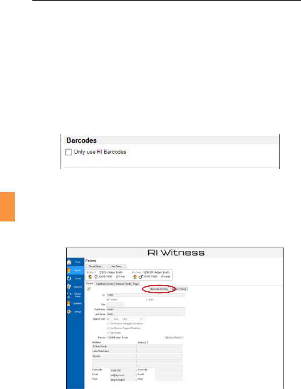
1. Open
2. Fromthepaentdetailswindowclick. See Figure 7-2.
Figure 7-2 RI Witness™ Manager
Secon 7
66
Cryo Witnessing
7
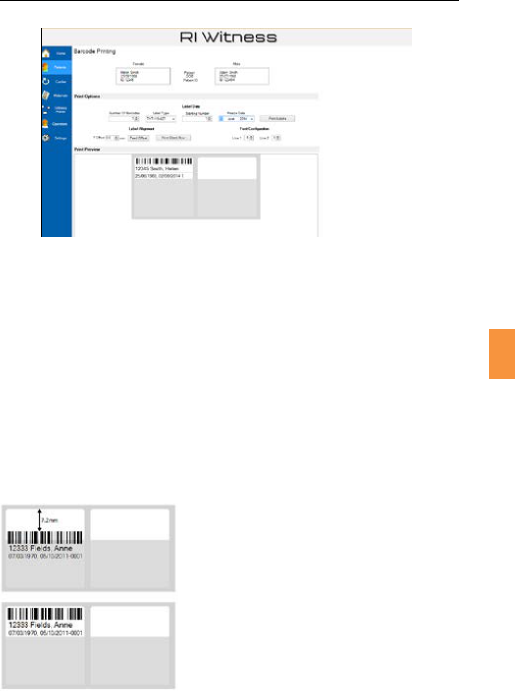
Figure 7-3 Barcode prinng window
3. To print barcodes make sure that a correct label printer is plugged into the computer with the
correct label stock loaded into it.
4. Select
• The required number of barcodes
• Thestarngnumber
• The freeze date of the barcodes.
5. A preview of the barcodes that will be printed is shown in the . The last number
onthesecondlineisthesamplenumberforthispaent.Thiscanbeeditedallowingreprinng
ofaparcularbarcode,forexampleiftheinialprinngwasmisaligned.
6. Click .
7. If you are using small style labels you may need to print a blank row to gain access to the printed
labels. To print a blank row of labels, click .
8. Tochecktheprintedlabels,measuretheYOsetbetweenthetopofthebarcodeandthetopof
thenextlabelandsettheprintheadposionontheprintertothisvalue.
Printheadpos.Y
+7.2 mm
1
2
Figure 7-4 Aligning the label print stock
1. The rst print shows incorrect alignment.
2. Alignment is corrected by seng the
printhead Y posion
Secon 7
Cryo Witnessing
67
7
Intheworkareaapaentcanbechosenbyscanninginasamplebarcodethathaspreviouslybeen
assignedtothispaent.
When compleng a witness point that includes a barcoding step, the barcode, either a brand new
barcodeorabarcodepreviouslyassignedtothecurrentpaent,mustbescannedpriortotheWitness
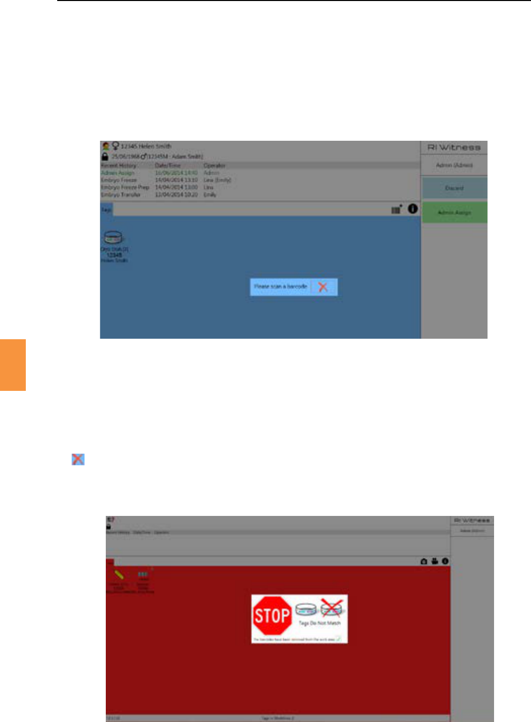
PointConrmaonscreen.SeeFigure7-5.
Figure 7-5 Scanning a barcode
Ifthebarcodehasnotbeenseenbythesystembeforeitwillbeassignedtothepaentaerthewitness
pointisconrmed.
Ifthebarcodehasalreadybeenscannedandassignedtoadierentpaent,themismatchalarmis
acvatedandthedieringpaentisshownonthemismatchscreen.Clickingonthesmall
nexttothedisplayedmismatchedpaentwillallowthemismatchscreentobeclosedandareason
aached.SeeFigure7-6.
Figure 7-6 Barcode mismatch
Secon 8
68
RI Witness™ Manager for Traceability
8
Materialtypes,egdishes,pipeesandmediamustbedenedforusewithinTraceability.Abarcode
readermaybeusedtoidenfybatchlotnumbers,expirydates,etcorthesedetailsmaybeentered
manually.Batchesareopenedorclosedtoreecttheiravailabilitywithinthelab.
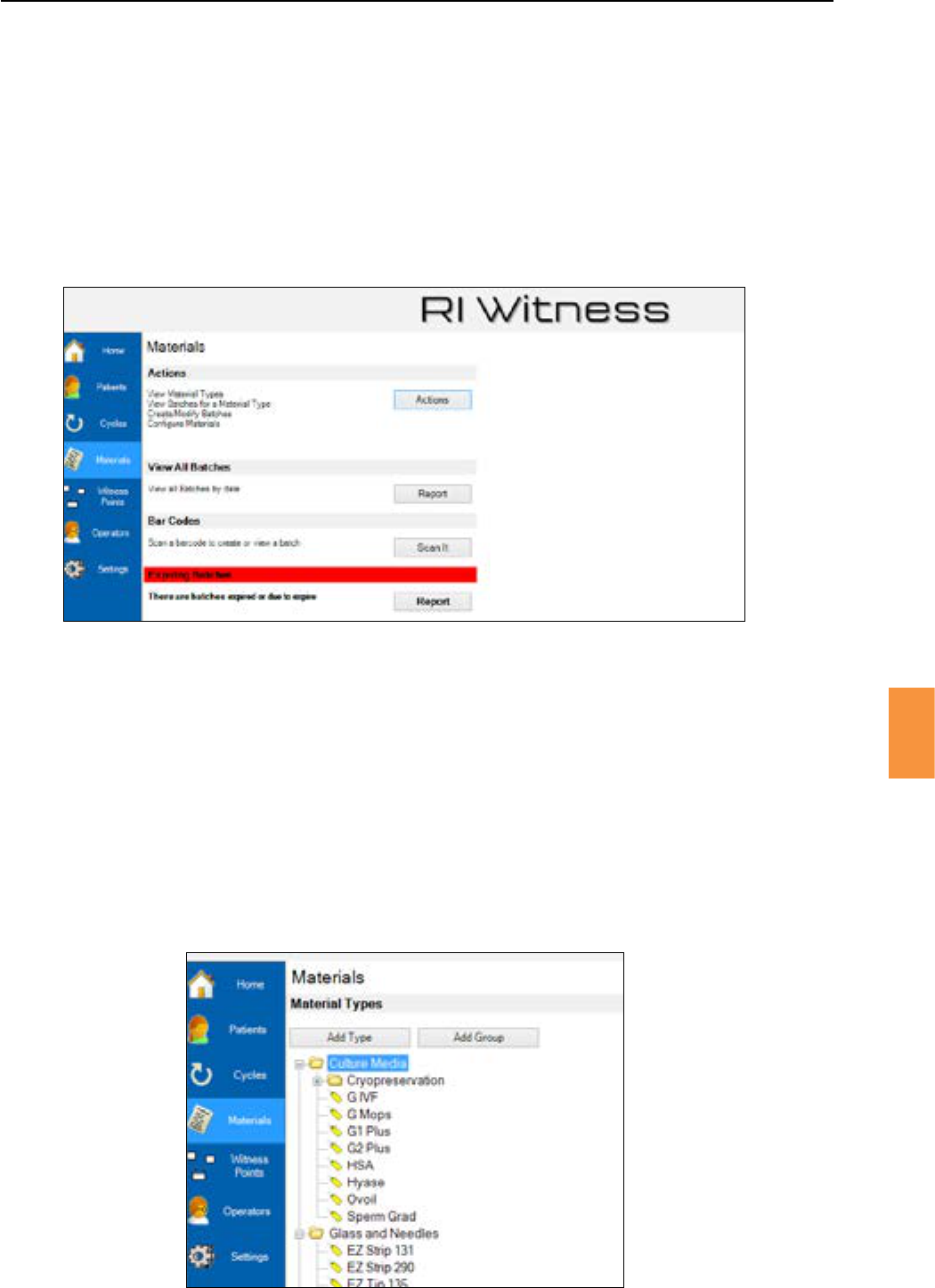
Click the mainmenubuontoviewthematerialsrelatedfeaturesofTraceability.SeeFigure
8-1.
Figure 8-1 Materials management
Materialtypesmustbeconguredbeforethedetailsofadeliveredbatchmayberecorded.
1. Click the mainmenubuon.
2. Then click to view a list of all material types.
3. Use and to specify the top level of your materials hierarchy. See
Figure 8-2.
4. Right click a group and select toextendthehierarchy.
5. Right click a group and select to add a new material type to that group. See Figure 8-3.
Figure 8-2 Viewing all material types
Secon 8
RI Witness™ Manager for Traceability
69
8
Figure 8-3 Right click to add a sub group
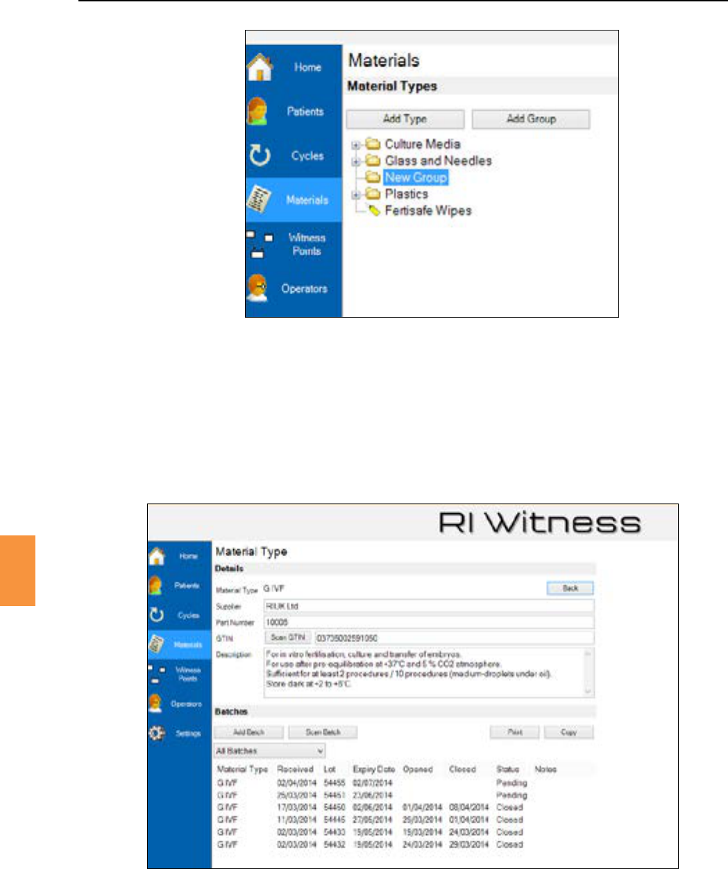
Double click a material type, or right click and select to view the material type
details. See Figure 8-4.
Figure 8-4 Material type details
SomematerialsaremarkedwithaGS1barcode.AGS1barcodemaycontainvariouscombinaonsof
expirydate,lotnumberandauniqueproductidenerknownasaGTIN.Hereweareonlyinterested
inaproductidener.
1. If you have a barcode, click and scan the barcode.
2. Manually enter a unique product part number if no GTIN is available.

Secon 8
70
RI Witness™ Manager for Traceability
8
GS1isaglobalbarcodestandardthatmaycontainaUniqueProductIdener(GTIN)andmayalso
containlotnumberandexpirydateinformaon.Someproductshaveabarcodethatdoesnotadhere
totheGS1standard.SomeGS1barcodesdonotcontainalltheinformaonhighlightedabove,egabox
ofbolesmayhaveabarcodethatcontainsGTIN,lotandexpiryinformaonbutanindividualbole
barcodemayonlyhaveLotandExpiryinformaonbutnoGTIN.
Traceability can interpret GS1 barcodes.
A Traceability buon must be clicked to interpret a GS1 barcode, eg click or or
.
Treatmentcycletypesmustbeconguredandlinkedwithmaterialtypes.
1. Click .
2. Then .
3. Then the tab to view the materials linked to a cycle type.
4. Tick the materials within the list that are to be associated with the treatment cycle type.
5. Press .
Aspreviouslydescribedin“Secon6-RIWitness™Manager”onlyadministratoroperatorsmaycreate
cycletypes. Traceabilityadminoperatorsmayaddionallyconguretherangeofmaterialsthatare
used when performing a treatment cycle type.
Anewlycreatedcycletypewillnotbeassociatedwithanymaterials.Usethematerialscheckboxesto
specify the range of materials that will be used for the selected cycle type. See Figure 8-5.
A new batch of a GTIN barcoded material may be scanned directly into Traceability.
1. Click themainmenubuonandthenclickthebuon.
2. Youwillbepromptedtousethebarcodescannertoreadthebarcode.Scanthebarcode.
3. As the materials type is already logged in the system, it will recognise the GTIN barcode and add
thenecessarydetailsofthatbatchofmaterialstothesystem,eglot,expirydate,etcwithinthe
Batch Details page.
Materials that are not GTIN barcoded are selected by navigang to the appropriate “material type
details”screen.
1. Click the mainmenubuonthenclick to show a list of all materials.
2. Double click the material that is being processed to show the Batch Details page for that
material. See Figure 8-7.
3. Alistofexisngbatchesofthismaterialisshown.Click to open the batch
detailswindowforanewlycreatedbatchandllinthebatchdetails.SeeFigure8-6.
4. Click to create a new batch if a GS1 barcode is available.
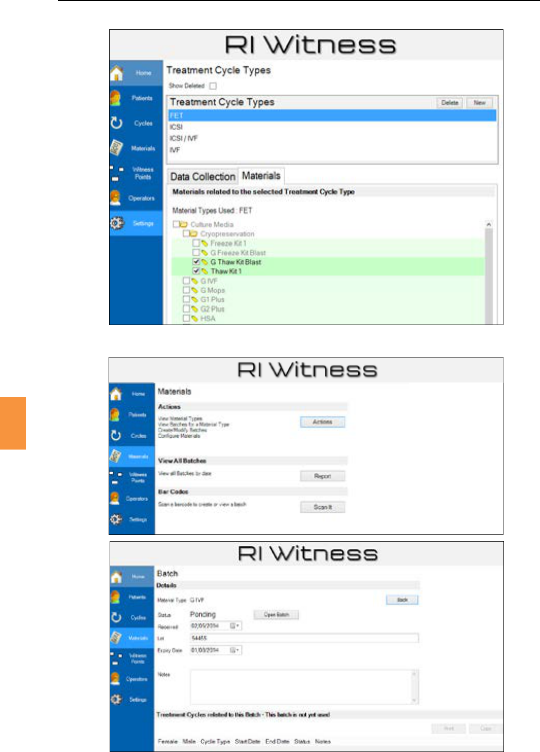
Secon 8
RI Witness™ Manager for Traceability
71
8
Figure 8-5 Material type details checkboxes specify the range of materials associated with each cycle type
Figure 8-6 Creang a new batch by scanning a barcode
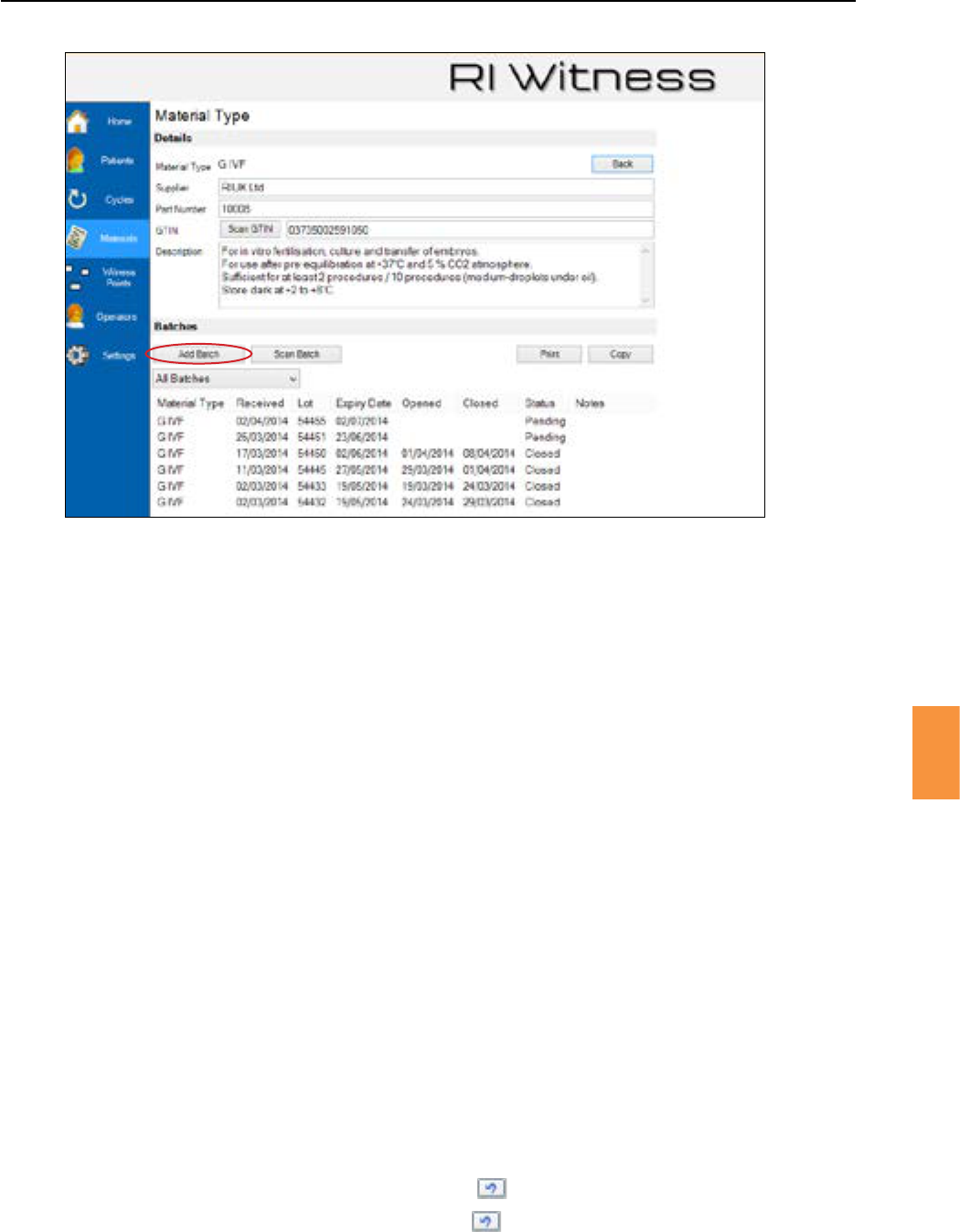
Secon 8
72
RI Witness™ Manager for Traceability
8
Normalbatchoperaonsarestatuschanges,eg
• : The batch of materials will shortly be opened and used
• The batch of materials has been opened and is in use within the lab
• Thebatchofmaterialshasbeenclosed,hasallbeenusedup,hasexpired,cannolonger
be used.
Batchesarenotrounelydeleted.
If a batch is created in error then an admin operator may delete it.
1. Click the mainmenubuon.
2. Click .
3. Double click the material type to be deleted.
4. The list of batches will be shown. Right click the appropriate batch and select .
Anewlycreatedbatchwillbeassignedastatusof“Pending”.Click when the batch is made
availableforuse.Thedetailsdisplayedforanopenbatchwillincludeallpaenttreatmentcyclesthat
are in progress. See Figure 8-8.
When a batch is no longer in use, click tochangethebatchstatusfrom“Open”to“Closed”.
If a batch is opened in error, click the buon toreturnthebatchstatusto“Pending”.
If a batch is closed in error, click the buon toreturnthebatchstatusto“Open”.
Figure 8-7 Lisng all batches of a specic material type
Click “Add Batch” to manually create a batch
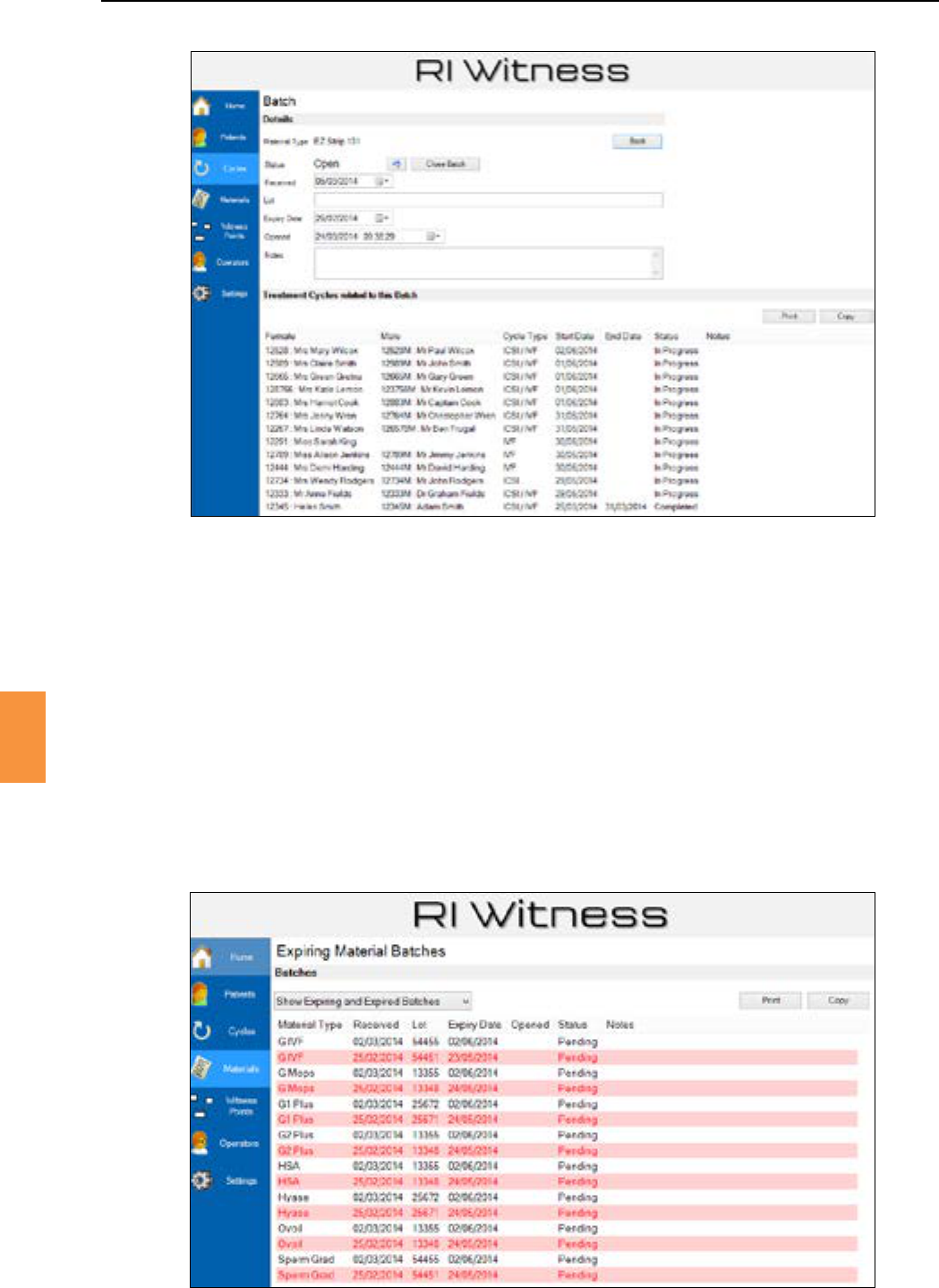
Secon 8
RI Witness™ Manager for Traceability
73
8
Figure 8-8 Paent treatment cycles related to a batch of materials
Whenbatchesarecreatedanexpirydateisrecorded.Ifanycurrently“Open”or“Pending”batchesare
expiredorwithin7daysofexpirythenanexpirybuonwillbeavailableonthemainMaterials
screen. See Figure 8-9.
Doubleclickanexpiredbatchtoshowthebatchdetailsscreenfromwhichthebatchmaybeclosed.
Now remove the batch from use.
Theexpiryperiodcanbesettoyourrequiredmeperiod,ieextendedto10daysorshortenedto5
days.
1. Click in the main menu.
2. Click .
3. WithintheMaterialsseconamendthebatchexpirywarningeld.
Figure 8-9 Expired and expiring batches
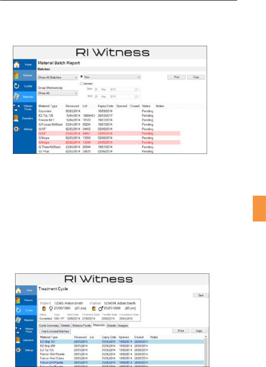
Secon 8
RI Witness™ Manager for Traceability
8
From the main Materials screen click toviewallbatches.Alteredlistofallbatchesisshown,
expiredbatchesarehighlightedinred.Thislistmaybelteredbydateandbybatchstatus.SeeFigure
8-10.
Figure 8-10 A ltered view of all batches
See“Secon5-RIWitness™Basicoperaon”fordetailsofcreangandmanagingatreatmentcycle.
When viewing the details of a treatment cycle Traceability operators may click the Materials tab to
show material batches related to this cycle. See Figure 8-11.
Batchescanbeexcludedfromcyclesbyrightclickingonthebatchandchoosing on the
contextmenu.
Excludedbatchescanbeviewedorhiddenbyclickingthebuonabovethe
batcheslist.Excludedbatcheswillbehighlightedblue.
Anexcludedbatchcanbeincludedagainbyrightclickingonanexcludedbatchandfromthecontext
menuleclicking. The batch will now be visible in the list of batches for the
cycle.
Figure 8-11 Material batches related to this cycle
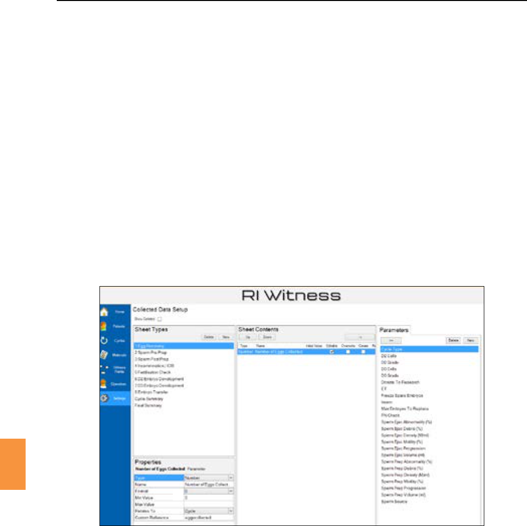
Secon 9
Data Capture
75
9
Hand wrien notes are oen taken whilst performing laboratory procedures. For example embryo
scoresandspermvolumesmightbewriendownonadatasheetandlatermanuallytranscribedinto
aclinicferlitydatabase.
The features of Data Capture described in this chapter allow data sheets to be designed in RI Witness™
Manager and data entry to be performed in the laboratory using the work area touch screen. Data entry
may also be performed in RI Witness™ Manager.
1. Click
2. Then click toenterthesetupscreenfordatacollecon.Sheetdesignis
performed using this screen.
The Collected Data Setup screen, Figure 9-1, is divided into 4 regions. Note that region 4 shows the
properesofanentryselectedfromregions1,2or3.
Figure 9-1 Collected data setup
1
3 2
Region 1 shows a list of all the sheet types that have been created. Click to add a new sheet,
setthenameofthenewsheetusingtheproperesinregion4.
Parametersareeldsthatmaybeplacedonadatasheet.Forexample,aparameternamed
“SpermVolume”thatrequiredanumericalvaluemightbeaddedtoan“Andrology”datasheet.
Region 2 lists the parameters that have been created and may be added to the contents of a
sheet.
Click the buontoaddaparametertoasheetcontents.Theparameterwillmovefrom
region 2 to region 3.
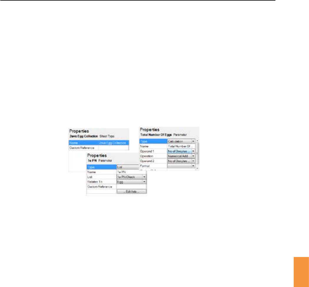
Secon 9
76
Data Capture
9
Region 3 shows the content layout of the selected sheet type. The contents of a sheet are
parameters that have been added to the sheet from region 2. To change the layout order,
highlight the parameter by clicking it. Then use the and buonstoposionitinthe
order required.
Onceaparameterhasbeenaddedtoasheetcontents,addionalaributesmaybeset.For
example,andefaultvaluecanbesetoraparametercanbemarkedasrequiredsothatan
operator must provide a value.
See“ParameterAributes”onpage87formoredetails.
Theproperesshowninregion4reectthemostrecentlyselectedentryfromregions1,2or3.
See Figure 9-2.
Figure 9-2 Examples of parameter properes and sheet properes shown in region 4
The contents of a sheet are called parameters.
1. Click intheparametersregion(2)tocreateanewparameter.Theproperesregion(4)will
show details of the newly created parameter. See Figure 9-3.
2. Enteranameforthenewparameter,eg“SpermVolume”.
3. Therstacontoperformonanewlycreatedparameterwillbetoselectaparametertypefrom
theProperesTypedropdownmenu.Parameterproperesdependontheselectedparameter
type.Forexamplethetexttypehasproperesminandmaxlengthwhereasacalculaonhas
twooperandsandanoperaon.
Figure9-3showstheproperesofeachparametertype.Figure9-4showstheParameterTypedrop
down menu.
Theproperesofanumericalparameterincludeaminimumvalue,amaximumvalueandanoutput
format.Theformatspeciesthenumberofdecimalplacestobeusedwhendisplayingnumbers.
Format meansthatthevalueenteredbyanoperatorwillnotbeformaed.Figure9-5showsthe
Format pull down.
Theproperesof a textparameter include a minimum length and a maximumlength.Leavethese
properes blank if length restricons are not required when the operator enters a value for this
parameter.
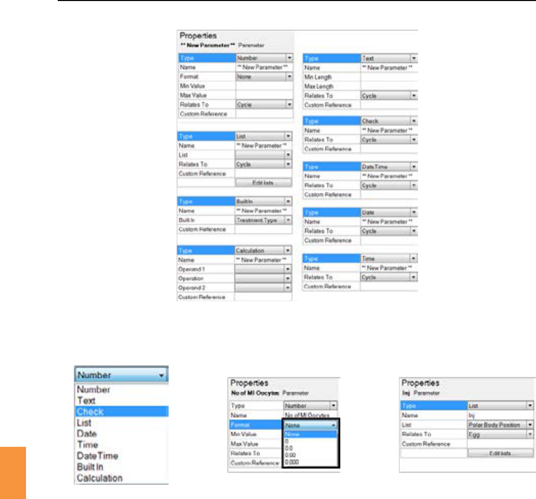
Secon 9
Data Capture
77
9
Figure 9-3 Parameter properes depend on the selected parameter type
Select from: Number, Text, Check, List, Date, Time, Date Time, Built In and Calculaon
Figure 9-4 Selecng a
parameter type
Figure 9-5 Selecng a
numerical format
Figure 9-6 The properes of a list
parameter
Listparametersallowtheoperatortochooseavaluefromapre-denedlist.Theproperesofalist
parameter are shown in Figure 9-6.
Click the buontoshowtheManageListswindow.TheexampleshowninFigure9-7highlights
the“PolarBodyPosion”listthatcontainsthe3values, and .The“Polar
BodyPosion”listisassignedtothe“”listparameter.SeeFigure9-6.
CheckparameterstakeYes/Novalues.
SheetspresentedbyRIWitness™Managerwillshowcheckboxes.Aworkareatouchscreenwilloer
aseleconof or .
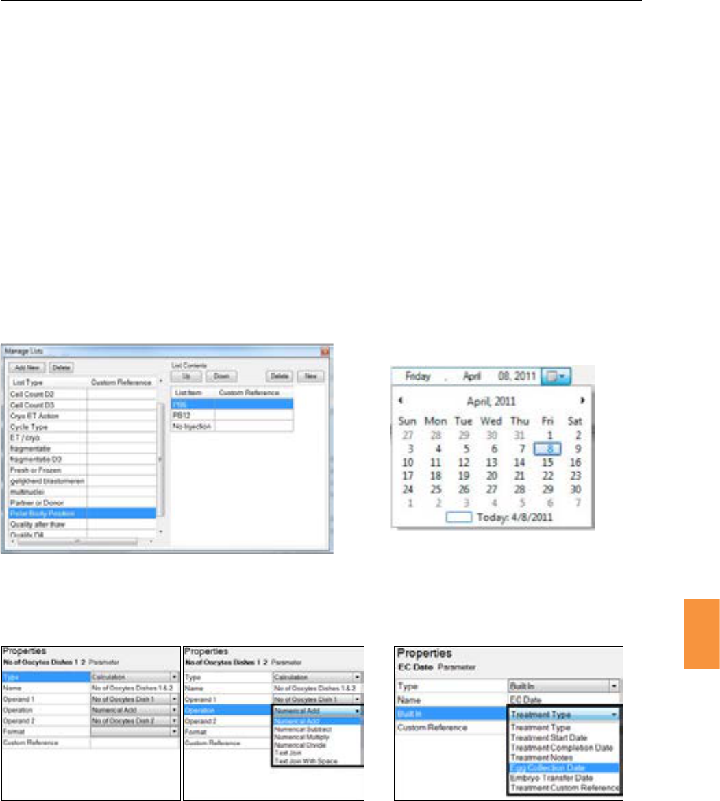
Secon 9
78
Data Capture
9
Figure 9-7 The manage lists window Figure 9-8 Seng a date me value
Figure 9-9 Adding two numbers using a calculaon parameter Figure 9-10 Selecng a built in value
DateandmevaluesareviewedandeditedusingRIWitness™Manager.Anoperatormaytypeavalue,
eg 12:30 or 14/08/2010 15:35. A date picker window is also available. Figure 9-8.
Calculaonsperformanoperaonontwooperands,egaddtwonumbersorjointwopiecesoftext.
Theoperandsofacalculaonmaybeparametersofanytypeincludingcalculaontypes.Aexample
calculaonisshowninFigure9-9.
Builtinparameterswilldisplayvaluesderivedfromtheassociatedtreatmentcycle,egtheeggcollecon
date. Figure 9-10 shows the available built in values.
Click the parameters buontomoveparameterstoasheetcontents(region3).Intheexample
shown in Figure 9-11, four list parameters have been added to the contents of the
sheet.
Figure 9-12 shows another example of sheet contents where two list parameter and four number
parameters form the contents of the Sperm Pre Prep sheet.
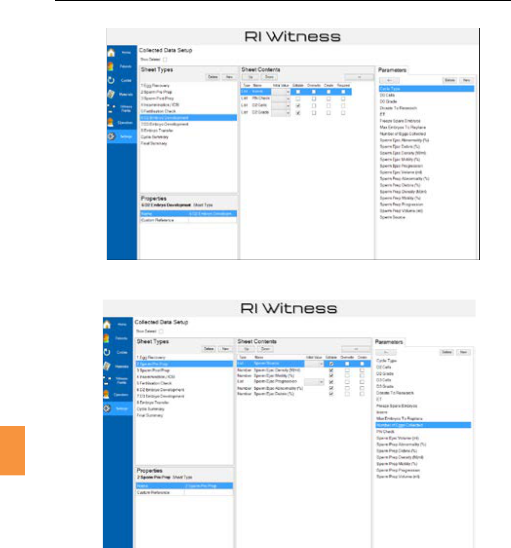
Secon 9
Data Capture
79
9
Figure 9-11 Adding parameters to the Embryo Development sheet
Figure 9-12 Adding parameters to the Sperm Pre Prep sheet
A parameter may be part of the contents of many sheets. The same parameter may be editable on
sheet A and sheet B and but not editable on sheet C. A parameter that appears on many sheets has
asinglesharedvalue.IntheaboveexampleavaluechangeonsheetAwouldautomacallyappear
changed on sheets B and C.
Thecontentsofasummarysheetmighttakeparametersfrommanyothersheets.See“CycleSummary
Sheets” on page 86 for more details. See “Parameter Aributes” on page 87 for more details of
theeditable/noneditableparameteraribute.
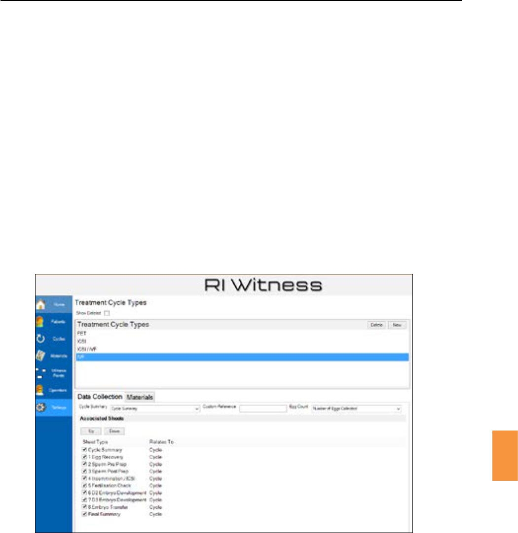
Secon 9
80
Data Capture
9
Figure 9-13 Use the checkboxes to associate sheets with the selected treatment cycle type
Sheets may be viewed and edited on a laboratory work area touch screen.
If sheets have been associated with the treatment cycle type being performed, then a
buonwillbeshownonthetouchscreen.SeeFigure9-14.
Touch the buontoseealistofavailablesheets.Touchabuontovieworedit
the sheet values. See Figure 9-15 and Figure 9-16.
Use the touch screen and arrowbuonstohighlightthesheetvaluetobeedited.Nocethat
thetypeofthevaluerequiredisindicatedtotheleofthevalueentrybox,eg123fornumericalinput,
ABCfortextinputandindicanguseofthearrowkeysforlistandYes/Noinput.
Treatmentcycletypes,egIVF,ICSIorIUI,willhavedierentdatacolleconrequirements.Forexample,
a sheet designed for IUI would not be used during an ICSI treatment.
1. Click then to associate sheet types with a treatment cycle type.
2. TheDataCollecontablistsallavailablesheets.Checktheboxesofthosethatareassociated
with the selected cycle type. See Figure 9-13.
3. Click .
Whenalistofsheetsispresentedtoanoperator,theywillbeorderedasspeciedhere.Usethe and
buonstochangethatorder.
During a treatment cycle an operator may view and edit the values on a sheet. Each treatment cycle
will start with blank copies of the sheet types that have been associated with the treatment type being
performed.
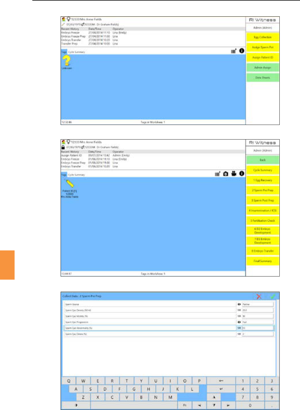
Secon 9
Data Capture
81
9
Figure 9-14 Touch the “Data Sheets” buon to view or edit all sheets associated with this treatment
Figure 9-15 Touch buons for each available sheet are shown in the work area
Figure 9-16 Use the touch keyboard to edit sheet values
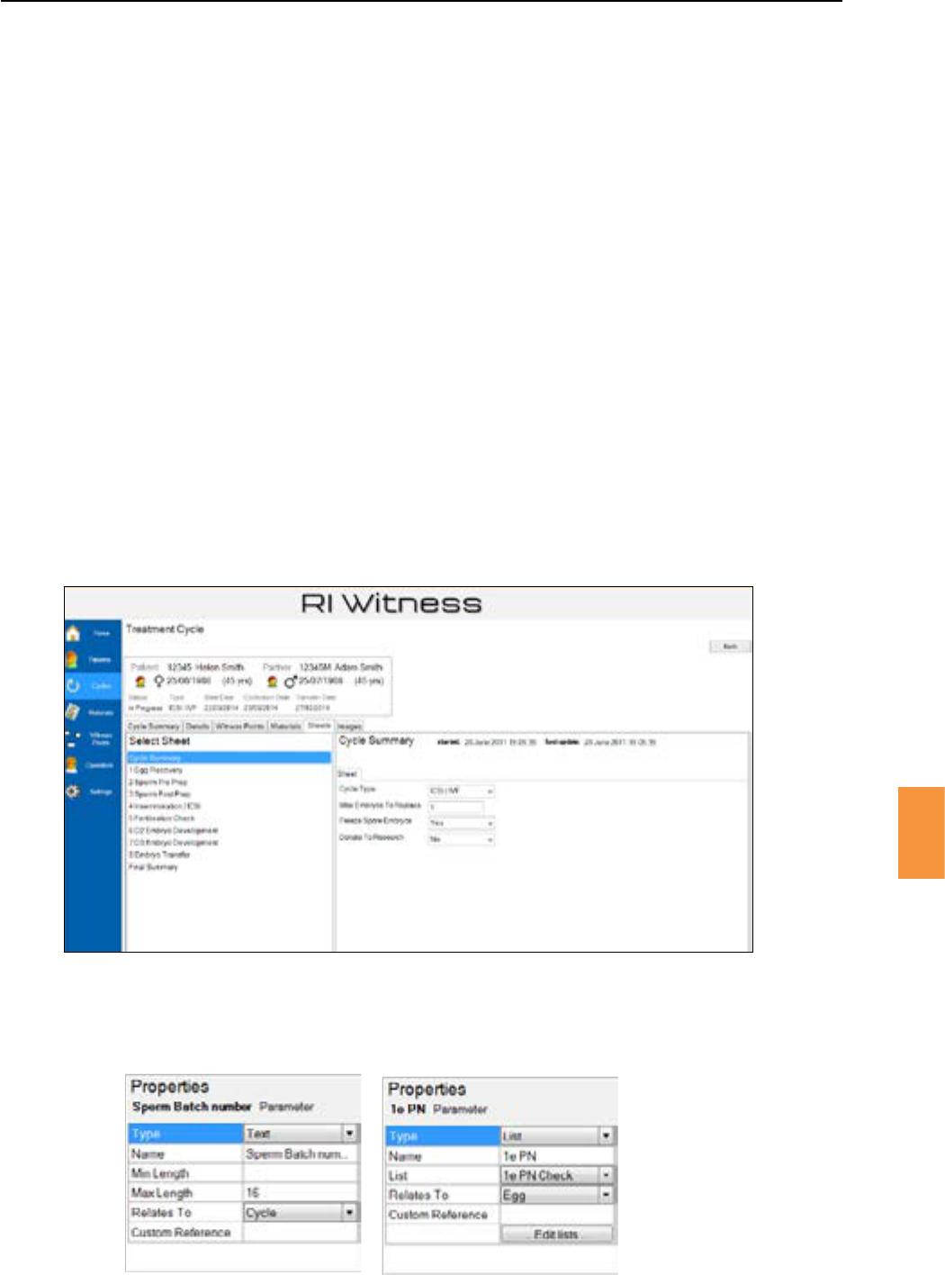
Secon 9
82
Data Capture
9
Data values will most likely be entered at the work area touch screen but sheets may also be viewed
and edited using RI Witness™ Manager.
1. Selectapaent.
2. Click the tab and then double click a cycle to show the Treatment Cycle
screen.
3. Click the tab to view or edit any sheet associated with this treatment shown in Figure
9-17.
TheproperesofaparameterincludeasengthatdefaultstoCycle,ieatreatmentcycle
doesnothavemulplevaluesforthisparameter.SeeFigure9-18.
However many parameter values will relate to an individual egg. Change the sengfrom
“Cycle”to“Egg”forsuchparameters.Eggrelatedparametersaredisplayedtotheoperatorasatable
containing one row for each egg. See Figure 9-19 and Figure 9-20.
On the work area touch screen, touch a row of the egg table to edit the values for that egg. See Figure
9-21. The circulararrowbuonsatthetopof thescreenmaybeused toselect anotheregg
without returning to the table view.
Figure 9-17 Eding sheet values with RI Witness™ Manager
Figure 9-18 The relates to seng defaults to cycle
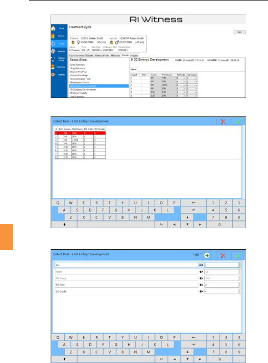
Secon 9
Data Capture
83
9
Figure 9-19 A RI Witness™ Manager view showing a table of egg related parameters.
Figure 9-20 A RI Witness™ work area touch screen view showing a table of egg related parameters
Figure 9-21 Entering values for egg number 1 at the work area touch screen
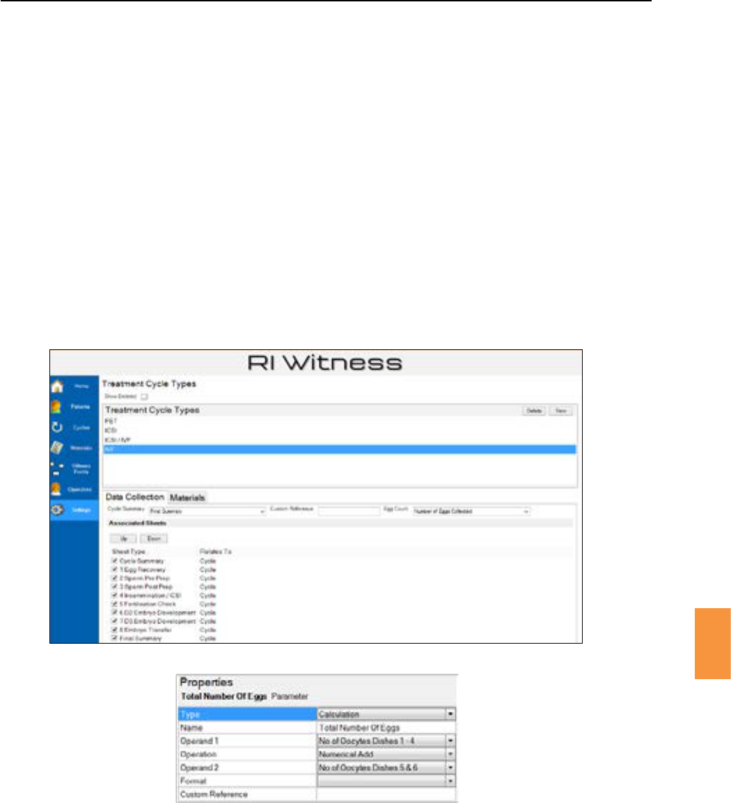
Secon 9
Data Capture
9
1. Click .
2. Then to view a list of treatment types.
TheDataCollecontabisusedtoassociatesheettypeswithatreatmenttypeasdescribedearlierinthis
chapter.TheDataCollecontabalsooersanEggCountParameterseng.Thedropdownmenufor
the Egg Count Parameter is a list of all parameters. Select one parameter that will contain a numerical
value. The selected parameter will control the number of rows in any table of egg related parameters.
The parameter selected to represent the egg count can be any parameter with a numerical value that
relatestoacycle.InFigure9-22theparametercalled“TotalNumberofEggs”hasbeenselectedfrom
a list of all parameters.
Asanexample,“TotalNumberofEggs”mightbeacalculaonparameterwhoseoperandsareother
parameters. See Figure 9-22.
Figure 9-22 The number of eggs involved in a treatment is set using the egg count parameter
Figure 9-23 This calculaon parameter has been selected as the egg count parameter in the example
shown in Figure 9-22
Changes to the value of the parameter set as the will change the number of rows
in any table of egg related parameters.
Ifthenumberofeggsisincreased,thenthenumberofrowsinalleggtableswillautomacallyincrease.
Ifthenumberofeggsisdecreased,thenthenumberofrowsinalleggtableswillnotautomacally
decrease. A decrease in the number of eggs will be indicated in RI Witness™ Manager as an
. See Figure 9-24.
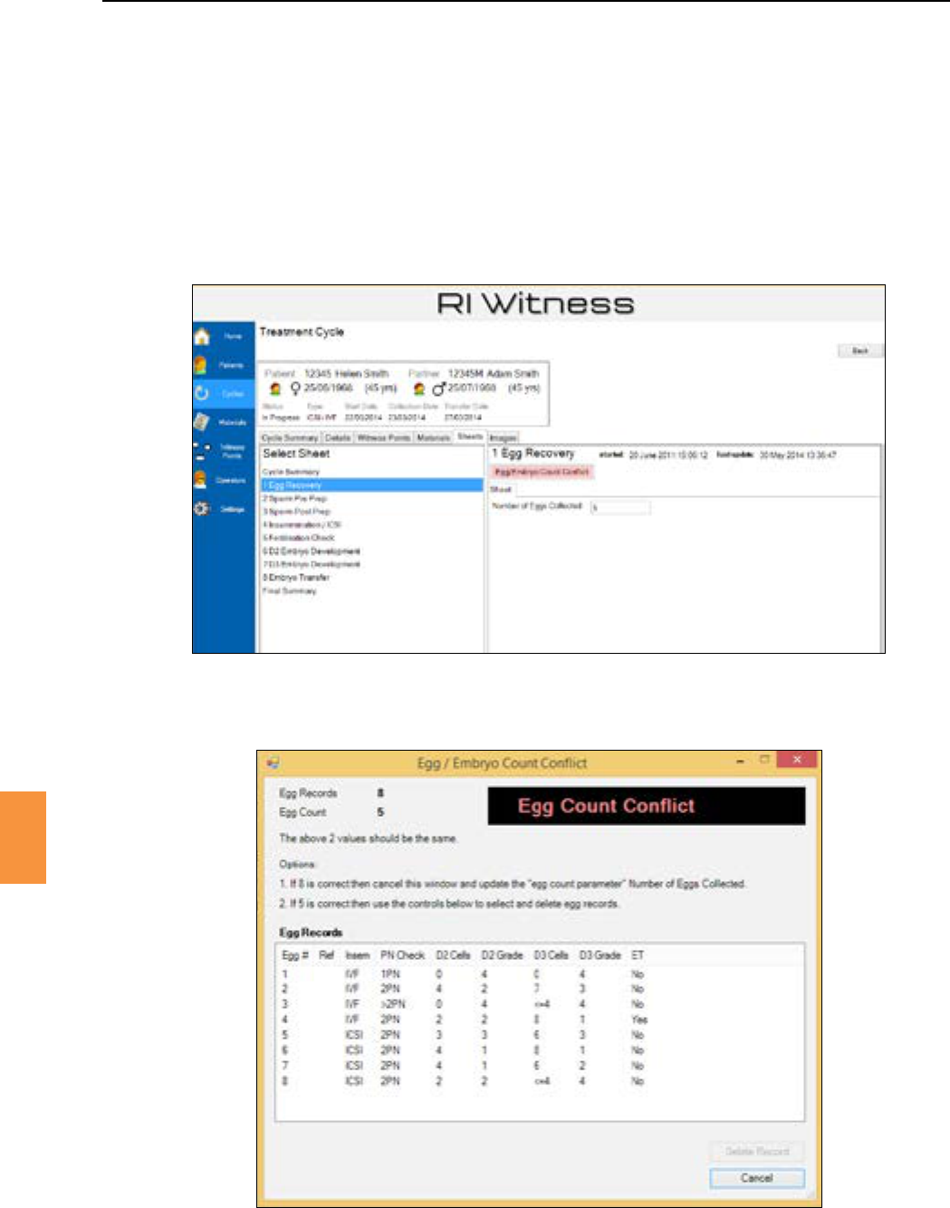
Secon 9
Data Capture
85
9
A conict resoluon window is shown when the buon is clicked. See
Figure9-25.Theconictresoluonwindowallowstheoperatortomanuallyselecttheeggrecordsthat
willbedeletedtoachievetherequireddecreaseineggcount.Theconictwillberesolvedwhenthe
number of egg records equals the value indicated by the Egg Count Parameter.
If it is decided that a decrease must be “undone”, then click the buon to exit the conict
resoluonwindowandincreasethevalueoftheEggCountParametertomatchthenumberofegg
records.
Figure 9-24 The Egg/Embryo Count Conict buon is shown if the value of the parameter selected as the egg
count parameter is decreased
Figure 9-25 The Egg/Embryo Count Conict window
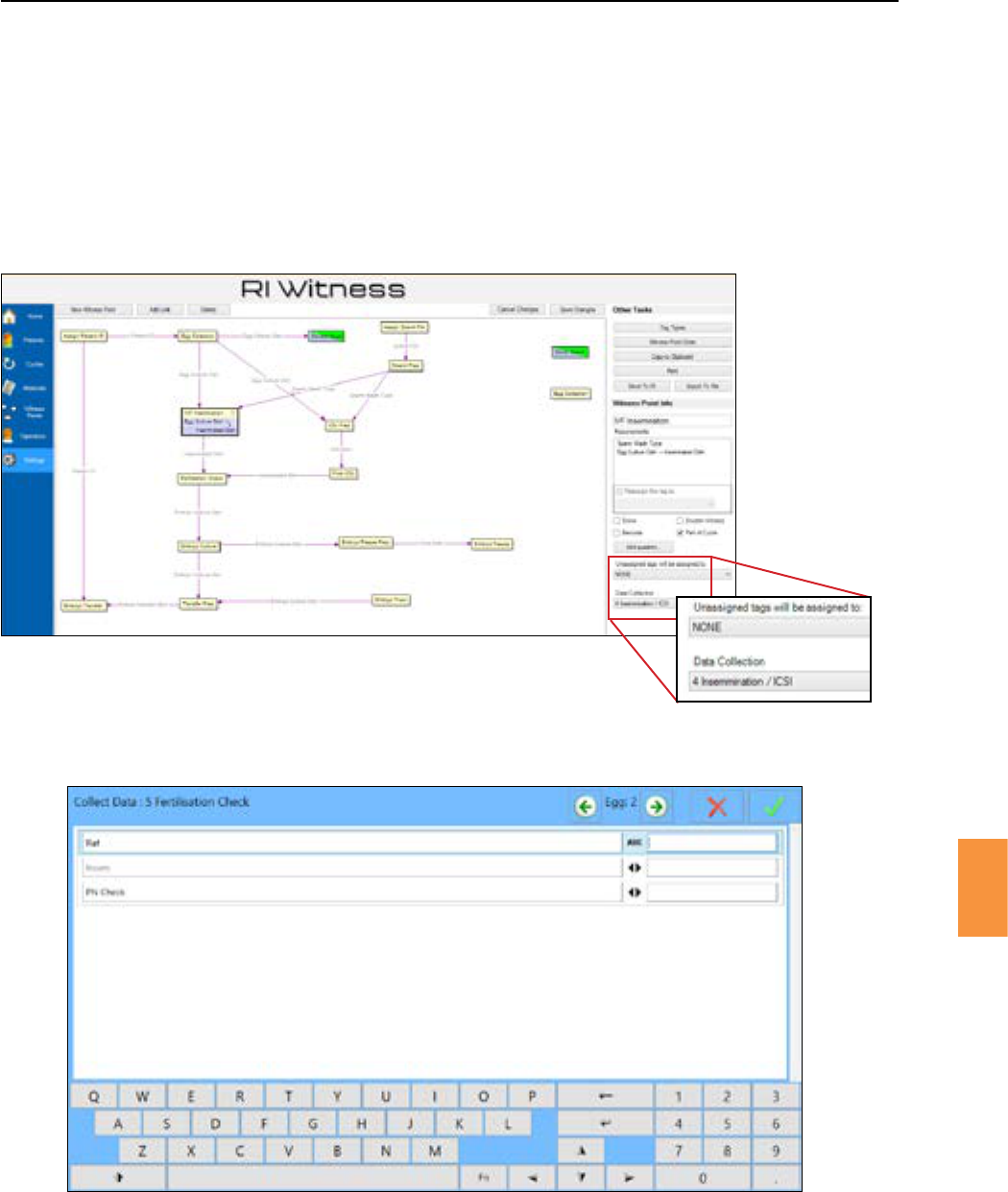
Secon 9
86
Data Capture
9
The work area touch screen buonoersaccesstoallthedatasheetsthathavebeen
associated with a treatment type.
Amoreselecveapproachtodatacolleconispossiblebylinkingasheettypetoawitnesspoint.See
Figure 9-26.
When a touch screen buonistouched,thelinkedsheetwillbeautomacallypresented
so that the operator may enter data related to the procedure being performed. See Figure 9-27.
Figure 9-26 The selected witness point “IVF Inseminaon” is linked to the data collecon sheet
“ 4 Inseminaon/ICSI”, see above at boom right
Figure 9-27 A witness point will trigger the presentaon of a linked data collecon sheet
Any sheet type may be selected as the cycle summary sheet.
1. Click in the main menu bar.
2. Then click .
3. Use the drop down menu to select the sheet type that will become the
summary sheet for this treatment type. See Figure 9-28.
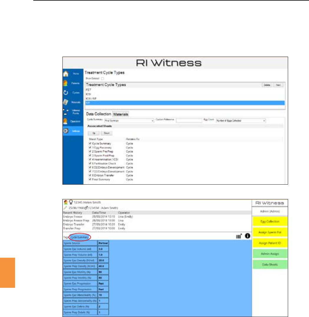
Secon 9
Data Capture
87
9
Figure 9-28 Select one sheet to become the cycle summary sheet
Figure 9-29 Touch the cycle summary buon to see the cycle summary sheet
Touch again to return to the original display
Atypicalsummarysheetwouldshowparametervaluesfrommanyothersheets.See“SharedBetween
Sheets”onpage79formoredetails.
Quick access to a read only view of the cycle summary sheet is visible in the work area via the touch
screen Buon.SeeFigure9-29.
Parameters that have been added to a sheet contents may be given sheet specic aributes. Click
then . See Figure 9-30.
Click in the column and enter a value.
Inialvaluesarelinkedwiththe and checkboxes.
Aninialvaluesengwillbeignoredunlessacombinaonof and or is also checked.
See Figure 9-31.
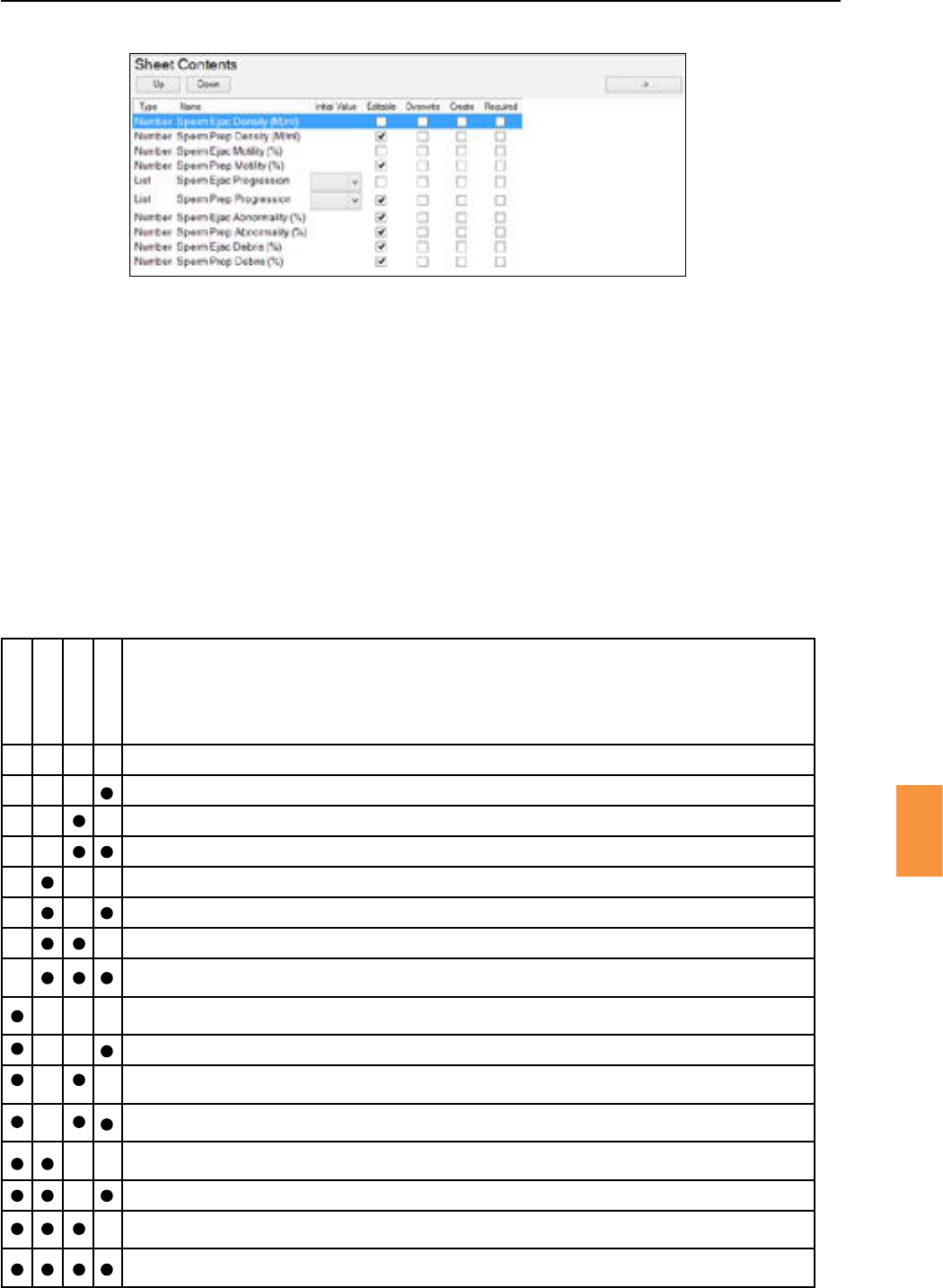
Secon 9
88
Data Capture
9
Thevalueofeditableparametersmaybechanged.Ifthischeckboxisnotcheckedthentheparameter
willbeshown“greyedout”andmaynotbechangedonthissheet.
Anoperatormustenteravalueforarequiredparameter.Thesheetcannotbesavedunlavalueis
entered. Required parameters are highlighted with an asterisk on the work area touch screen and in
red when viewed in RI Witness™ Manager.
The value may not be edited
n/a
Edingallowedbutmaybeleblank.
Avaluemustbeenteredbutitmaynotbeleblank.
Ifavaluealreadyexistsitwillbeoverwrienwiththeinialvalue.Theusercannotchangethevalue.
n/a
Ifavaluealreadyexistsitwillbeoverwrienwiththeinialvalue.Theusermaychangethevalue.
Ifavaluealreadyexistsitwillbeoverwrienwiththeinialvalue.Theusermaychangethevaluebutitmaynotbe
leblank
Ifnovalueexiststhenshowtheinialvalue.
The user may not change this value.
n/a
Ifnovalueexiststhenshowtheinialvalue.
The user may change this value.
Ifnovalueexiststhenshowtheinialvalue.
Theusermaychangethisvaluebutitmaynotbeleblank.
Theinialvaluebeshown,overwringanyexisngvalue.
The user may not change this value.
n/a
Theinialvaluebeshown,overwringanyexisngvalue.
The user may change this value.
Theinialvaluebeshown,overwringanyexisngvalue.
Theusermaychangethisvaluebutitmaynotbeleblank.
Whatdoesthiscombinaonmean?
Figure 9-31 Combining parameter aributes
Figure 9-30 Seng parameter aributes.
Inial Value, Editable, Overwrite, Create and Required
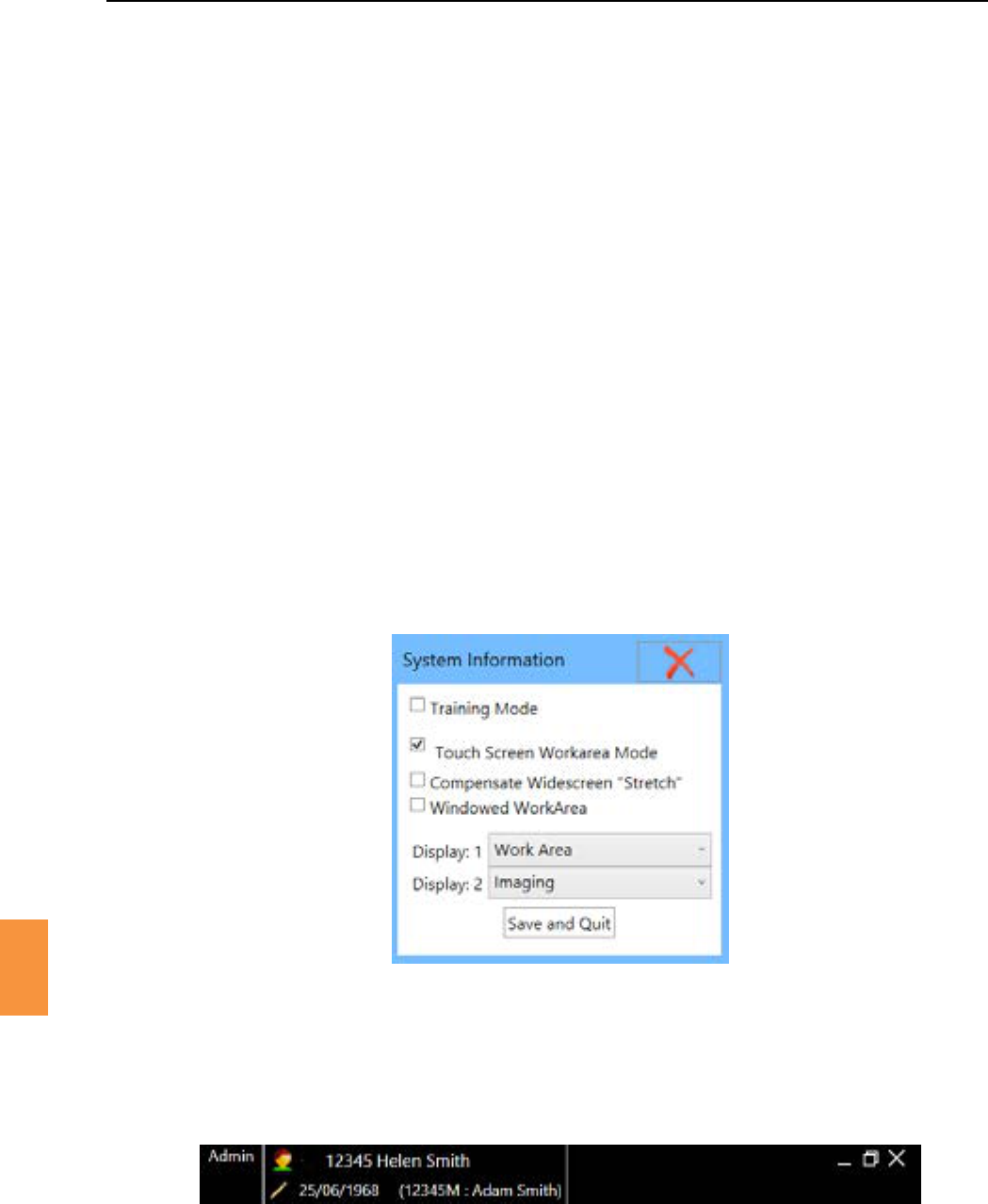
Secon 10
Imaging
89
10
A camera will need to be connected to the PC running RI Witness™ and the drivers installed correctly
toviewliveimageswithinRIWitness™.TheImagingsecuritydonglemustalsobeedtoaUSBport
and a valid Imaging license issued.
RIWitness™sowarewillautomacallyrecognisebothanalogueandcompabledigitalcameradevices
connected to the PC. If there is only one camera device detected, it will show the live image for that
device.Ifmulplecameradevicesareconnected,itwillusethecamerathatwaslastselectedfromthe
videosourcedropdownbox.
IftherearemulplecamerasaachedtothePC,thedeviceyouwanttheliveimagetobeviewedfrom
may be selected.
To do this, select the Camera from the dropdown list on the panel.
MulpleImagingscreenscanbeconguredforusewithImaging.
1. Open
2. Unlocksengs.
3. Touch .
4. Setyourdesiredconguraon
Iftheworkareaiswindowed,thenmulpledisplayswillnotbeshown.Windowedworkarea
isrecommendedforAdminPCswithreadersconnected.Toenablesimplyckthe
box.
5. ThecurrentoperatorandpaentwillbedisplayedonthesecondaryImagingscreen.
BothoperatorsandpaentsmaybechangedbyclickingtheappropriateareaontheImagingscreen.
Imagesarecapturedforthepaent’scyclecurrentlyacveintheworkarea.Imagescapturedforthe
acvecyclewillbedisplayedintheRIWitness™Managersortedbydateandme.
Figure 10-1 Combining parameter aributes
Figure 10-2 Imaging screen showing operator and paent
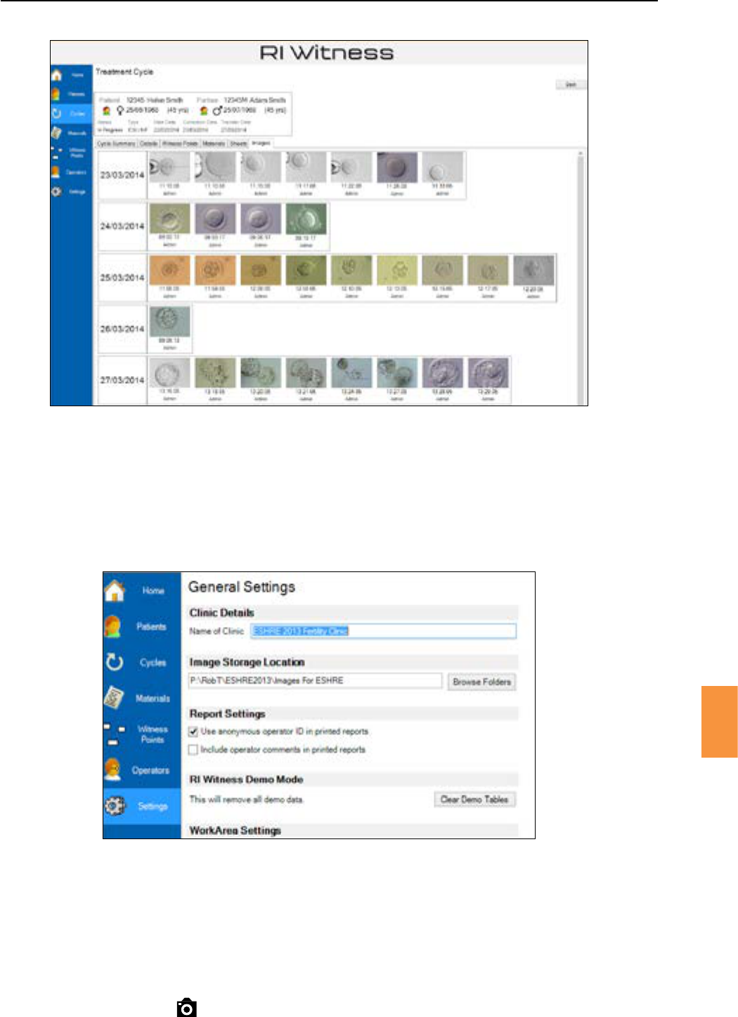
Secon 10
90
Imaging
10
Ensurethatthereisalocaonsettostorecapturedimages.ThisissetinRIWitness™Manager.
1. Click in the Main Menu tool bar.
2. Click .
3. SetthedesiredlepathwithintheImageStorageLocaoneld.
Figure 10-3 Images captured shown in the RI Witness™ Manager screen
Figure 10-4 Image storage locaon
This is available on both the work area screen and secondary Imaging screen.
1. Log in using your operator name and PIN.
2. Ensurethereisapaentwithanacve/opencycleintheworkarea.
3. Press the icon .

Secon 10
Imaging
91
10
This is available on both the work area screen and secondary Imaging screen.
1. Login using your operator name and PIN.
2. Ensurethereisapaentwithanacve/opencycleintheworkarea.
3. Click the icon .
4. Eachvideorecordingcanlastforamaximumofonehour.Thiseliminatestheproblemof
accidentallyleavingthesowarerecordingandpossiblyrenderingthecomputerunusable.
5. When freeze frame is set as keyboard shortcut, the live image recording can be paused. A
second press of the shortcut key will restart the live image recording.
6. Press or click to stop recording.
Available on the Imaging screen
There are three ways to zoom into an area on the screen.
1. Placethemouseatapointonthescreen.Clickandholdtherightmousebuon,thenrelease.
This will zoom to the preset zoom level into the spot where the mouse is placed. To zoom out,
clickandholdtherightmousebuon.
2. Place the mouse at a point on the screen and use the scroll wheel on the mouse (if available).
This will give the user control over how much digital zoom is given.
3. Usingthetoolbarattheboomofthescreen,clickthe+ icon to zoom in incrementally. To
zoom out by the same amount, click on the icon on the tool bar. The magnifying glass icon will
zoom in and out by the preset zoom.
Whilstusingdigitalzoom,athumbnailimageofthescreenwillappearinthetopleofthescreen.At
thetopofthispanelistheamountofmagnicaonyouareusing.Whenzoomedoutfully,thispanel
will not appear on the screen.
Zooming in and zooming out can also be achieved using the foot pedal.
Available on the Imaging screen
1. Click icon on the tool bar.
2. Click on the screen to select a start point for the measurement.
3. Clickonthescreenasecondmetoselectanendpointforthemeasurement.
The ends of the line can be dragged to change the measurement.
Linescanberemovedbyclickingthecrossinthecontextwindow.
Duringlaseroperaon,linesareshownbutcannotbedragged/createdandnomeasurementswillbe
displayed.
Lines and measurements are shown on an image when images are taken in Line Mode.
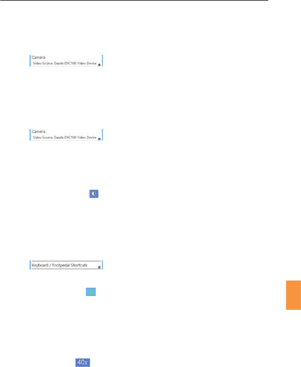
Secon 10
92
Imaging
10
Available on both the work area screen and secondary Imaging screen.
1. Open
2. Unlocksengs.
3. Press
4. Click on thetoallowtheseleconofcameras.Clickingontherequiredcamera
in the list will change the live image to that of the selected camera.
Available on both the work area screen and secondary Imaging screen.
1. Open
2. Unlocksengs.
3. Press
4. Tick (forcameradevicesthatsupporttheseopons).
5. Tick (forcameradevicesthatsupporttheseopons).
Available on the Imaging screen.
1. Click the icon from the Imaging screen.
2. Drag the Preset Zoom slider to the required zoom.
Available on both the work area screen and secondary Imaging screen.
1. Open
2. Unlocksengs.
3. Press .
4. Clickthecorrespondingeditbuontoassignashortcut.
5. Hold down the key or press the foot pedal to assign.
6. Click or press the to save the shortcut.
Oncetheshortcutsaresetup,presstheshortcutkeysorthecorrespondingfootpedaltoacvatethe
command.
Available on the Imaging screen.
1. Click the on the tool bar.
2. Clicktherequiredobjecvemagnicaon.
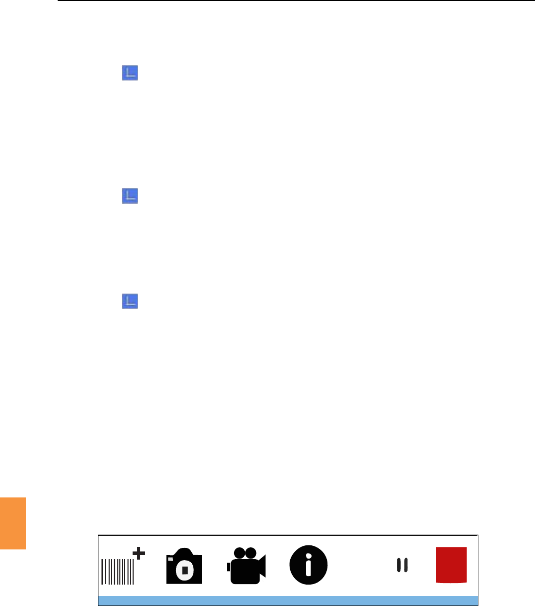
Secon 10
Imaging
93
10
Available on the Imaging screen.
1. Click on the tool bar.
2. Click the buon.
3. Click Themagnicaonwillbethesameasthecurrentmagnicaon.
4. Clicktherequiredobjecvetoeditobjecvemagnicaonandneadjustmentvalues.
Available on the Imaging screen.
1. Click on the tool bar.
2. Click the buon.
3. Click Xnexttoanobjecve.
Available on the Imaging screen
1. Click on the tool bar.
2. Click the buontoopentheObjecveCalibraonpanel.
3. Place an object of known dimensions (a stage micrometer is supplied with each system for this
purpose)intheeldofview.
4. EnsurethattheobjecveselectedinImagingmatchesthatbeingusedonthemicroscope.
5. Thestagemicrometersuppliedmeasures100μmbetweenthelongerlines.Forbestaccuracy,
posioneachendpointofthelineatexactlythesamerelaveposiononthescale,for
exampleattherighthandedgeofeachvercalline.
6. Drag the rulers to the point where the stage micrometer is going to be measured from and use
theneadjustmentupanddownunltherulerscalematchesthestagemicrometer.
1. Tocongureascreenasapaentdisplaysimplyselectthe for the
desiredscreen.ThescreenwilldisplaytheRIlogounlthedisplayisturnedon.
On O
Figure 10-5
2. Toturnthepaentdisplayon/osothatitshowsthevideofromthecamera,clickthe or
buoneitherontheworkareaoronthepaentdisplaypanelontheImagingdisplay.The
Imagingdisplayshowsapreviewofwhatthepaentdisplaywillshow.SeeFigure10-5.
3. Totakeasnapshotofthevideotouseonthepaentdisplay,pressthebuononthe
workareaorpaentdisplaypanel.
4. To re-enable live streaming of the video, press .
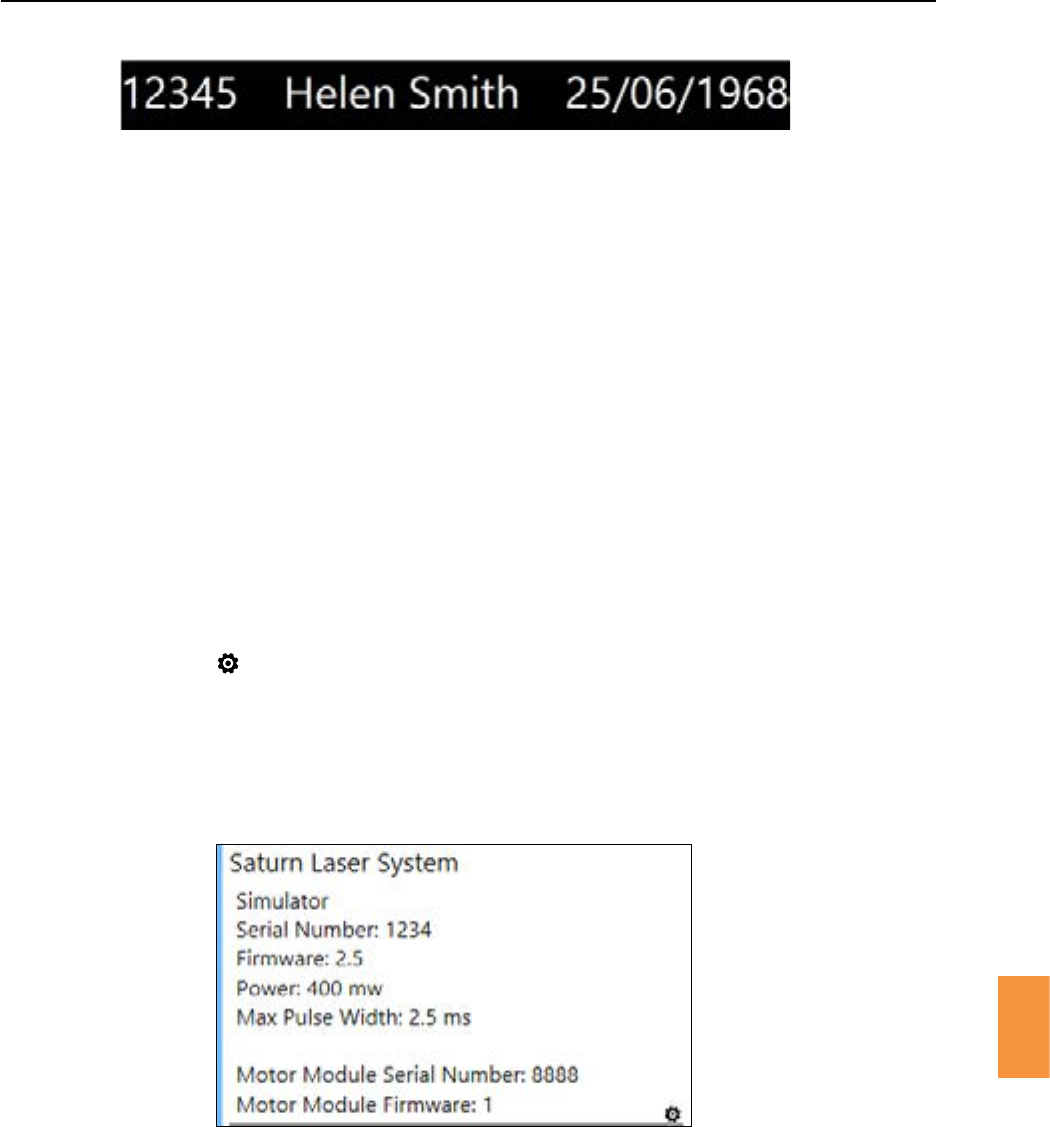
Secon 10
Imaging
10
Whenacurrentpaentisacvatedviatheworkarea,thepaentnameandIDwillappearonthe
PaentDisplay.Itwillonlybevisibleifthepaentdisplayisturnedon.SeeFigure10-6.
5. Closingthemainwindowwillalsoclosethepaentdisplay.
RIWitness™canberunalongsideandinconjunconwithSaturn™LaserSystems.Pleaserefertothe
Saturn™LaserSystemusermanualforfullinstrucons.
Toaccesssengsandinformaonfromtheworkarea
1. Open
2. Unlocksengs.
3. DetailedinformaonabouttheSaturn™LaserSystemwillbedisplayed.
4. Press icon toenableBiopsyorMul-PulseModes.
Figure 10-6 Informaon shown on paent display
Figure 10-7 Saturn™ Laser System informaon

Secon 11
Troubleshoong
95
11
Tags Reading
IntermientlyorOnly
in Certain Areas
RF noise Many devices in the lab can cause RF noise.
ContactRIoraRIrepresentave.
Antenna not tuned
Metal objects may change antenna tuning.
Posiontheantennawhereitwillbeused.If
the antenna that is not tuned is an auto tuning
antennafollowtheinstruconsshownin“RF
Calibraon”onpage19,otherwisecontactRI
oraRIrepresentavetoretunetheantenna.
Antenna not tuned
Metal objects may change antenna tuning.
Posiontheantennawhereitwillbeused.If
the antenna that is not tuned is an auto tuning
antennafollowtheinstruconsshownin“RF
Calibraon”onpage19,otherwisecontactRI
oraRIrepresentavetoretunetheantenna.
Looseconnecon Checkforanycablesunpluggedornotghtened
fully.
Control unit / antenna /
mulplexerfaulty ContactRIoraRIrepresentave.
Tags Not Reading
Broken tag Checkthetagonadierentantenna.
Tag not encrypted
Use the . Non encrypted tags
are shown in red.
RF noise Many devices in the lab can cause RF noise. Contact
RIoraRIrepresentave.
WorkAreaconguraon
Use the to check that the
number of antennas matches the number in
the work area. Also check that the temperature
controllerisspeciedcorrectly.
Antenna not tuned
Metalobjectsmaychangeantennatuning.Posion
the antenna where it will be used. If the antenna
that is not tuned is an auto tuning antenna follow
theinstruconsshownin“RFCalibraon”onpage
19, otherwise contact RI or a RI representave
to retune the antenna.
Looseconnecon Checkforanycablesunpluggedornotghtened
fully.ContactRIoraRIrepresentave.
Control unit / antenna /
mulplexerfaulty ContactRIoraRIrepresentave.

Secon 11
96
Troubleshoong
11
Mulplexer / Control
Unit / Temp Controller
Missing
RI Witness™ WorkArea
conguraon
Use the to check that the
number of antennas matches the number in
the work area. Also check that the temperature
controllerisspeciedcorrectly.
Looseconnecon Checkforanycablesunpluggedornotghtened
fully.
Control unit / antenna /
mulplexerfaulty
ContactRIoraRIrepresentave
Database Missing
RI Witness™ WorkArea
conguraon
Use the to check that database
connecon is specied correctly. Contact your IT
department for assitstance.
Looseconnecon Check for any unplugged or loose network cables.
Replace with a known good cable.
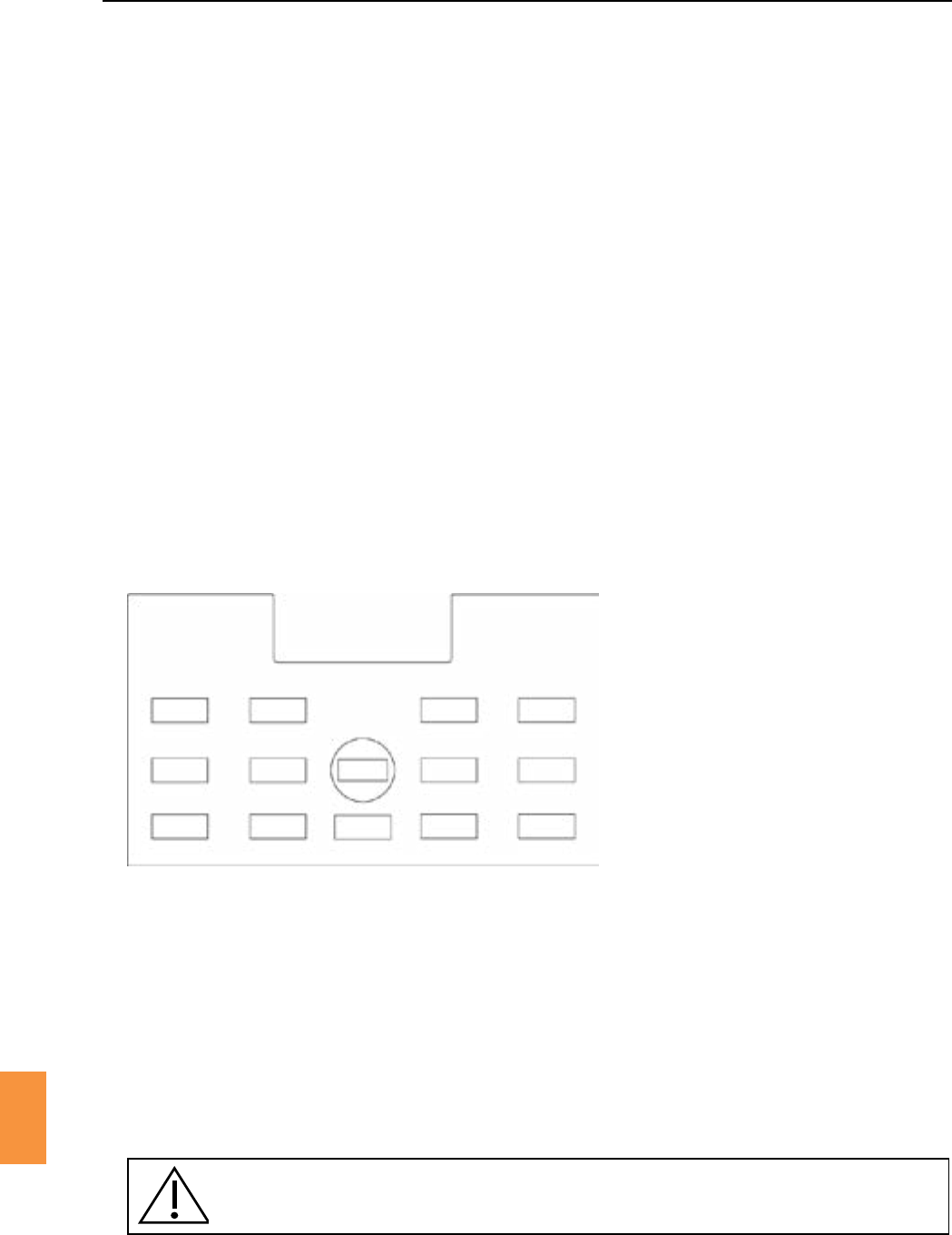
Secon 12
Temperature Calibraon
97
12
Beforecheckingthetemperatureprole,itisimportanttoestablishifthereaderisaoneortwochannel
reader.Thiscanbedonebyturningothecontrolboxandrestarng.Atthebeginningofthestart-up
procedurethecontrolboxscreenwillshowackoracrossnexttothechannelnumber(seeheated
controlboxdisplaywarnings).Ifthereaderisasinglechannelitwilldisplayacknexttochannelone
andacrossnexttochanneltwo,whilea2channelwilldisplayacknexttoboth.
Thetemperaturegradientovertheheatedplateshouldnotexceed1.5°C.Inasinglechannelreader
the temperature dierence between the centre of the glass window and the highest temperature
measuredawayfromthewindowshouldnotexceed3.0°C.Foradualchannelreaderthetemperature
dierencebetweenthecentreoftheglasswindowandthehighesttemperaturemeasuredawayfrom
thewindowshouldnotexceed1.5°C.
Follow this guide to posion small amounts of thermal paste at each point to be measured.
Complete the form ‘RI Witness™ Heated Antenna Service Record’ for each heated reader. The latest
formsareavailablebycontacngRI.
Use a thermometer probe secured with masking tape to measure the temperature at each of
the 14 points. Allow 3-5 minutes for the probe reading to stabilise at each measurement point.
TheobjecveoftemperaturecalibraonistoensurethatthetemperatureindicatedbytheRIWitness™
sowareiswithin0.2°Cofthetemperaturemeasuredonaheatedreadersurface.
Werecommendusingathermometercalibratedat37°Cedwithasmallthermocoupleprobe,such
as the RI IVF Thermometer.
Ensure that the work area setup is as it will be used, eg microscope light on, fan on, etc.
Figure 12-1 Temperature prole template
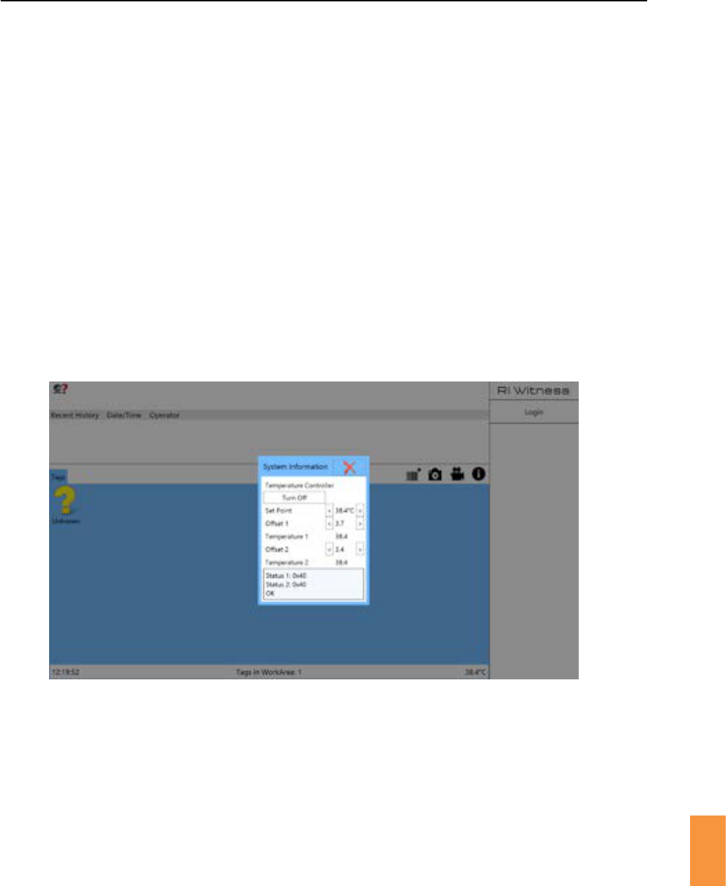
Secon 12
98
Temperature Calibraon
12
Switch the control unit ON.
Make surethe controlunit RF powerisswitchedo toavoidinterferencewithathermometer
reading.
Place a small amount of thermal compound 5cm to the right of the reader window. Posion a
thermometer probe in the compound and secure the probe with masking tape.
Waitunlthethermometertemperaturestabilises.Thiscantakeupto45minutes.
Compare the temperature shown in the work area soware with the thermometer reading.
Adierencewithin+/-0.2°Cisacceptable.
If the readings are outside the above requirement then click to open the temperature
oset sengs and make adjustments. Increase the oset to increase the displayed reading,
decreasetheosettodecreaseit.
Allowasmalldelayfortheosetchangetoregister.
Figure 12-2
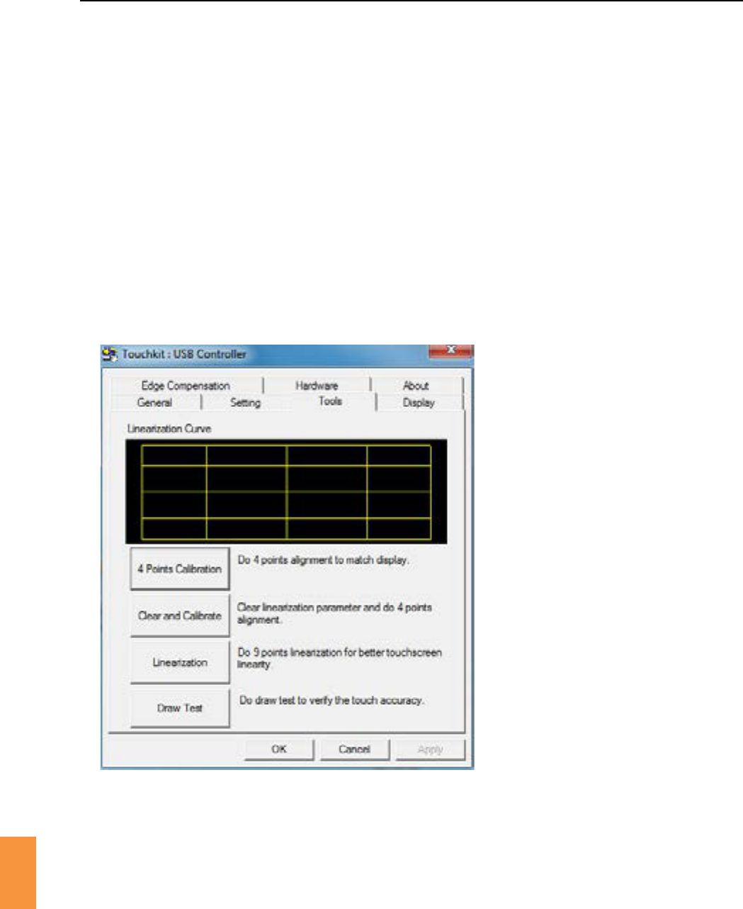
Secon 12
Temperature Calibraon
99
12
Figure 12-3 Touchkit : USB controller screen shot
Thetouchscreencursorshouldaccuratelytracktheposionofanoperatornger.Ifaccuracyproblems
areexperiencedthenuseamousetoacvatethecalibraonulityandperformthefollowingchecklist.
1. Double click the desktop icon, then click on the tab.
2. The touch screen shows a blinking Xinthelowerlecorner.TouchandholdtheblinkingXunlit
stopsblinkingandmovestothenextcornerposion.Repeatthetouchandholdforeachcorner
ofthescreen.Oncompleona“calibraonnished”messageisdisplayed.
3. Touchthescreeninafewrandomlocaons.Repeatthecalibraonifthecursorisnotcorrectly
posioned.
Secon 13
100
Care and Maintenance
13
RIWitness™readersmaybecleanedwithasoclothandmilddetergent.Areadermaybeliedand
returnedtoitsoriginallocaon.Donotdisconnectthecablesaachedtoanyreader.
Do not use solvents for cleaning.
Do not disconnect readers.
Donotchangetheposionofreaders.

Secon 14
Repairs and Returns
101
14
AssumingRIWitness™isregularlymaintainedandrounelyserviced,itshouldperformasrequiredfor
aminimumof7yearsconnualuse,aerwhichmewerecommendyouconsideritsreplacement.
Shouldyounoceimpairedperformanceand/oranyissueswheresafetyiscompromised,orhaveany
otherconcernsduringtheuseofRIWitness™,seektheadviceofRIortheirauthorisedrepresentave
promptly.
In the event that you have a problem with a RI instrument, please follow the procedure below to ensure
promptaenon.
1. Readthe‘Troubleshoong’secon.
2. If you require any further help contact your distributor or RI directly. RI will try to resolve the
problem as quickly as possible.
If the product is no longer serviceable it must be sent back to RI to be destroyed in an
environmentally safe way. Do not dispose of RI Witness™ products with ‘normal’ waste.
1. ContactRItoobtainaReturnedMaterialsAuthorisaon(RMA)number. Goods will not be
replacedorrefundedwithoutprioragreementandclearlystangtheRMAnumber.
2. Pack the item carefully in its original packaging. RI will not accept responsibility for damage due
toincorrectpackaging.Replacementitemsoraddionalrepairswillbeinvoiced.
3. ClearlylabelthepackagewiththeRMAnumber,markthepackage“Urgent-ReturnedItemsFor
Repair”,andshiptotheaddressonthenextpage.Goodsshouldbeinsuredfortheirfullvalue
during shipping.
Tel:+44(0)1326372753Fax:+44(0)1326378783
E-mail: service@research-instruments.com
Website: www.research-instruments.com
IncompliancewiththeEuropeanMedicalDeviceDirecve93/42/EECasamended,itisyourdutyto
informRIifyoubelievethisdevicehas,ormayhave,causedorcontributedtothedeathofapaentor
userortoaseriousdeterioraonintheirstateofhealth.

Secon 14
102
Repairs and Returns
14
Thank you for purchasing a RI product. To help RI develop the best tools for ART, we rely on customer
feedback.Ifyouhaveanysuggesonsforhowwecanimproveourproductsortheinformaonwe
provide with them, please send them to feedback@research-instruments.com.Yourfeedbackwillhelp
usdeveloptheproductandsupporngmaterialstomeetyourfutureneeds.
Thank you.