REnex Technology PT209-0104003 2.4GHz DSSS Wireless Modem User Manual
REnex Technology Limited 2.4GHz DSSS Wireless Modem
Contents
- 1. User Manual
- 2. FCC Information
User Manual

PT-209G/219G
User Manual
Version 2.2
REnex Technology Limited
Room 601-603, 6/F., 1 Science Park East Avenue,
Hong Kong Science Park, Pak Shek Kok, N.T., Hong Kong
Phone: +852 2607 4088
Fax: +852 2607 4099
www.renextechnology.com
Purpletooth®
2.4GHz Wireless Modem
Direct Sequence Spread Spectrum

- ii -
This document is produced for users of Purpletooth® PT-209G/219G, the spread spectrum
wireless modem from REnex Technology Limited. It covers the operating principles and
capabilities of Purpletooth® PT-209G/219G. It is highly recommended to read this document
before using Purpletooth® PT-209G/219G in order to operate it correctly and have its best
performance.
WARNING
Changes or modifications to this unit not expressly approved by the party
responsible for compliance could void the user’s authority to operate the
equipment.
This manual contains information of proprietary interest to REnex Technology Limited. It is
supplied in confidence to purchasers and other authorized users of Purpletooth® PT-
209G/219G Wireless Modem. By accepting this material, the recipient agrees that the
contents will not be copied or reproduced, in whole or part, without prior written consent of
REnex Technology Limited.
The electronic equipment described in this manual generates, uses, and radiates radio
frequency energy. Operation of this equipment in a residential area may cause radio
interference, in which case the user, at his/her own expense, will be required to take
whatever measures necessary to correct the interference.
Information in this document is subject to change without notice.
REnex Reference Number: R-001-4000-018
Printed Date: November 2004
© 2001-2004 REnex Technology Limited. All rights reserved.
Purpletooth® is registered trademark of REnex Technology Limited.
Microsoft and Windows are registered trademarks of Microsoft Corporation.
HyperTerminal is copyrighted by Hilgraeve Inc, and developed for Microsoft.
All other products mentioned in this document are trademarks or registered trademarks of their respective
holders.

- iii -
FCC Information
This device complies with Part 15 of the FCC Rules. Operation is subject to the
following two conditions: 1) this device may not cause harmful interference,
and 2) this device must accept any interference received, including
interference that may cause undesired operation.
NOTE: This equipment has been tested and found to comply with the limits
for a Class B digital device, pursuant to part 15 of the FCC Rules. These limits
are designed to provide reasonable protection against harmful interference in
a residential installation. This equipment generates, uses and can radiate
radio frequency energy and, if not installed and used in accordance with the
instructions, may cause harmful interference to radio communications.
However, there is no guarantee that interference will not occur in a particular
installation. If this equipment does cause harmful interference to radio or
television reception, which can be determined by turning the equipment off
and on, the user is encouraged to try to correct the interference by one or
more of the following measures:
-- Reorient or relocate the receiving antenna.
-- Increase the separation between the equipment and receiver.
-- Connect the equipment into an outlet on a circuit different from that to
which the receiver is needed.
-- Consult the dealer or an experienced radio/TV technician for help.
RS-232 DB9 shielded cable with ferrite must be used with this unit to ensure
compliance with the Class B FCC limits.
CAUTION: The model num
ber PT
-
209G and PT
-
219G
have maximum transmitted output power of 0.07
Watt. It is recommended that the transmit antenna be
kept at least 20 cm away from nearby persons to
satisfy FCC RF exposure requirements. The antenna
and transmitter must not be co-lo
cated or operating
in conjunction with any other antenna or transmitter.

- iv -
CAUTION:
RISK OF EXPL
OSION IF BATTERY IS REPLACED BY
AN INCORRECT TYPE.
DISPOSE OF USED BATTERIES ACCORDING TO THE
INSTRUCTIONS.

- v -
WARRANTY
REnex Technology Limited (REnex) warrants this product to the original owner purchased
directly from REnex or an authorized distributor to be free of defects and workmanship for a
period of one year from the date of purchase.
REnex’s obligation under this warranty is limited to replacing or repairing defective parts of
our product under normal use and service. REnex is not liable for any damage, which
results from abnormal use, abuse, improper operation, accident or inability to use this
product.

- vi -
Contents
WARRANTY.............................................................................................................................................. v
1. General.......................................................................................................................1
1.1 Product Overview ............................................................................................................................ 1
1.2 Features ........................................................................................................................................... 1
2. Physical/Electrical Attributes ...................................................................................2
2.1 PT-209G/219G Physical Layout ....................................................................................................... 2
2.2 LED Indications............................................................................................................................... 3
2.3 RS-232 DB-9 Connection................................................................................................................. 4
3. Setup PT-209G/219G.................................................................................................5
3.1 Setting up Connections..................................................................................................................... 5
3.2 Checking the Link............................................................................................................................ 5
3.3 Using the USB Port.......................................................................................................................... 6
A. Technical Specifications ............................................................................................7
B. Antenna Specifications..............................................................................................8

1
1.1 Product Overview
The Purpletooth® PT-209G/219G Direct Sequence Spread Spectrum (DSSS) Wireless Modem is a
high performance wireless modem. It is designed to provide a long distance, high data rate and
robust platform for applications. It offers data communication capabilities to application equipment
via standard interfaces. Neither additional hardware nor software modification is required in the
application equipment to work with PT-209G/219G. By using a pair of PT-209G/219G modems,
users can transfer data between almost all types of equipment that use asynchronous serial
interfaces. The small size and superior performance of PT-209G/219G make it an ideal solution for
many applications. Typical examples are:
Traffic control
Remote monitoring
Telemetry
Remote camera/robot control
Mobile video transmission
Environmental monitoring
Emergency rescue
Premises security
Logistics
PT-209G is the standard version that conforms to the FCC, CE and China SRRC regulations. While
PT-219G is an enhanced version that bears the UL Class 1 Division 2/ATEX Group 2 Category 3
safety classification in addition to the FCC, CE and China SRRC radio approvals.
1.2 Features
Key features of PT-209G/219G:
Operates in license-free frequency band
Supports serial data I/O with handshaking and hardware flow controls
Supports high speed and high throughput data transfers via USB and Ethernet ports
Provides error-free data connections via built-in CRC-16 error detection and
automatic re-transmission
Offers high data rate and support long distance
Adopts the advanced Direct Sequence Spread Spectrum (DSSS) technology to
provide high interference immunity to protect on-air data from signal interferences
and malicious data trappings
Supports various data applications with efficient communication protocols
Easy to use, plug-and-play without specific software requirement
1. General
NOTE1:
This manual has been provided as a guide and reference for
installing and using PT-209G/219G
wireless modems. It is assumed that
users of PT-209G/219G modem have
either system integration or
system design experience.
2
2.1 PT-209G/219G Physical Layout
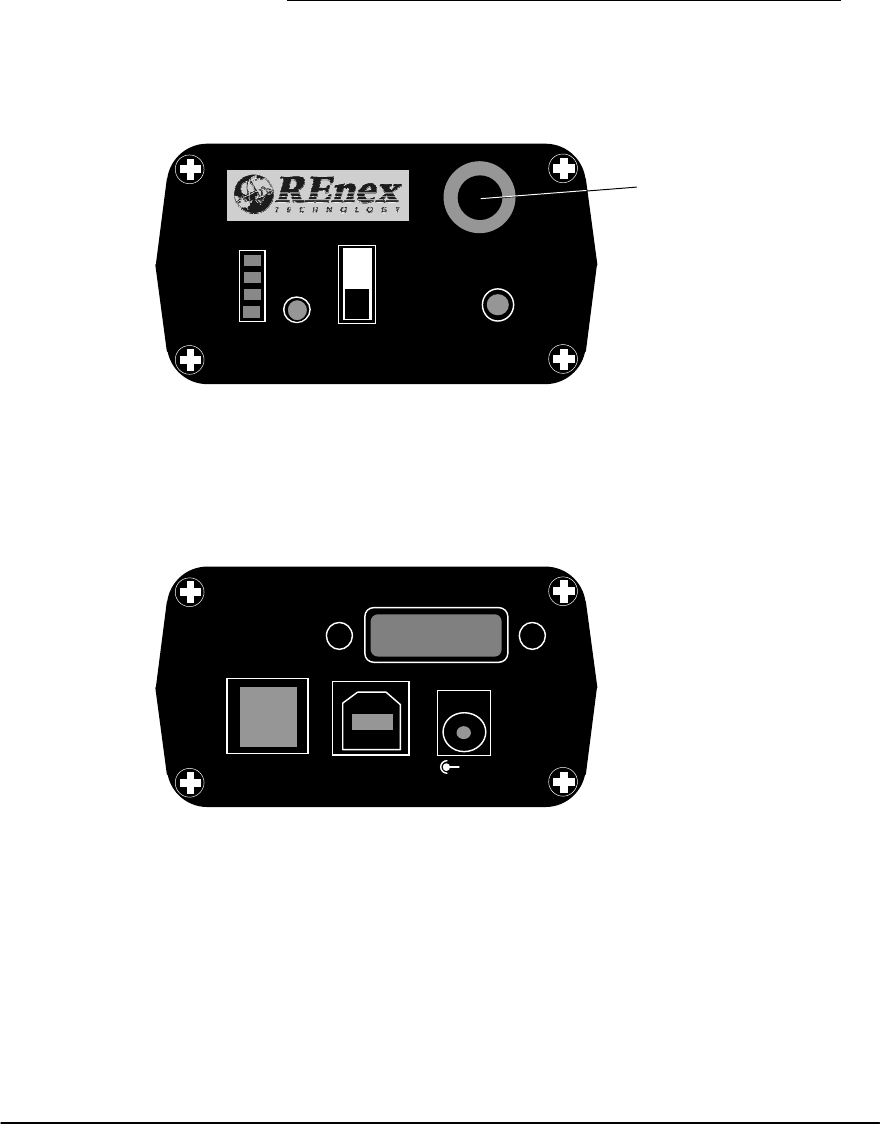
The following diagrams illustrate the front and rear panels of PT-209G/219G.
(a) Front panel
(b) Rear panel
Figure 1. Front and rear panels of PT-209G/219G modem.
2. Physical/Electrical
Attributes
RS-
232
LAN
USB
⊕
12V
Antenna
PWR
OK
Tx
Rx
CHARGING
ON
OFF CNFG
ANT.
3
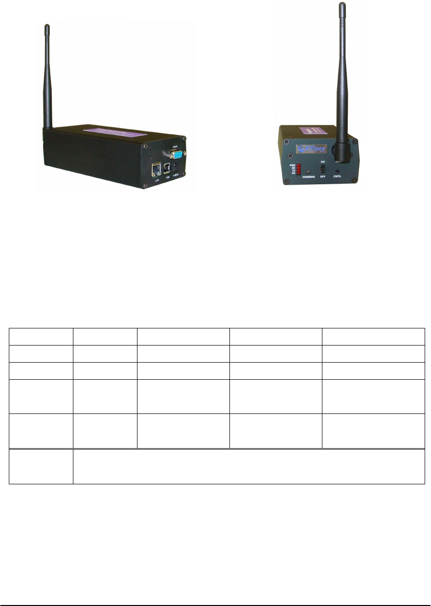
Photos of PT-209G/219G are depicted in the following figures:
Figure 2. Photos of PT-209G/219G modem.
2.2 LED Indications
Five LED’s are installed in PT-209G/219G modem as shown in Figure 1 (a). They indicate the
status of the modem and their definitions are listed in the following table:
Table 1. LED indications
On Off Dim Flash
Rx LED - No data receive Data link in active Receiving data
Tx LED - No data send out Data link in active Sending out data
OK LED* Procedure
success No procedure/
procedure failed - Procedure in
progress
Power LED - Power down Power up In power saving
mode
Charging
LED Red: Charging; Green: Fully charged
* Procedure means the slave registration/de-registration procedures. It is off in normal operations.

4
2.3 RS-232 DB-9 Connection
Pin assignments of the RS-232 port are as follows:
Table 2 Pin assignments of the RS-232 port
RS-232 port pin no. Pin name Signal direction
1 DCD -
2 RXD Output
3 TXD Input
4 DTR Input
5 GND -
6 DSR Output
7 RTS Input
8 CTS Output
9 RI -
5
3.1 Setting up Connections
PT-209G/219G modems are shipped from REnex with a pre-configured setting. They can operate
“out of the box”. Hence, the only thing users need to do is to make the appropriate connections
between the modem and their equipment via the RS-232 port, the USB port or the Ethernet port, and
then power up. The master and slave(s) shall communicate properly. For using the USB port, you
may need to install a driver for the first time plugging in your system. Please follow the
“Purpletooth® Family USB Driver Installation Guide” for the installation procedure.
3.2 Checking the Link
After finishing the physical connection setup mentioned above, PT-209G/219G should be ready. If
the performance of the communication link is not satisfactory or any linking problem is found, the
following steps may help you locate the problem.
Figure 3. Basic network mode.
1. Connect each modem to a serial port of a PC using direct RS-232 cable.
2. Start a terminal program such as Hyper Terminal (http://www.hilgraeve.com, it may be
found in Microsoft Windows OS) for each serial port. Make sure the baud rate and data
format settings agree with those of PT-209G/219G.
3. Characters typed at the master’s terminal should appear at that of the slave’s and vice versa.
4. The TX LED should flash during transmitting data to the RF link.
5. The RX LED should flash during receiving data from the RF link.
6. Adjust the modem separation and the antenna direction to locate positions with the best
performance.
3. Setup PT-209G/219G
NOTE 2:
PT
-
2
09
G/219G
is highly sensitive to obstacles in its
communication path. Make sure the communicating modems are in line
-
of-sight. Otherwise, the performance may drop significantly.
NOTE 3:
Antenna height is a critical factor. Try to put the antenna at a
position as high as possible.
Slave Master

6
3.3 Using the USB Port
An Internet access driver, called NDIS-USB driver, is provided in the CD-ROM inside the delivery
package. You can follow the installation guide in the CD-ROM to install it. After that, you can
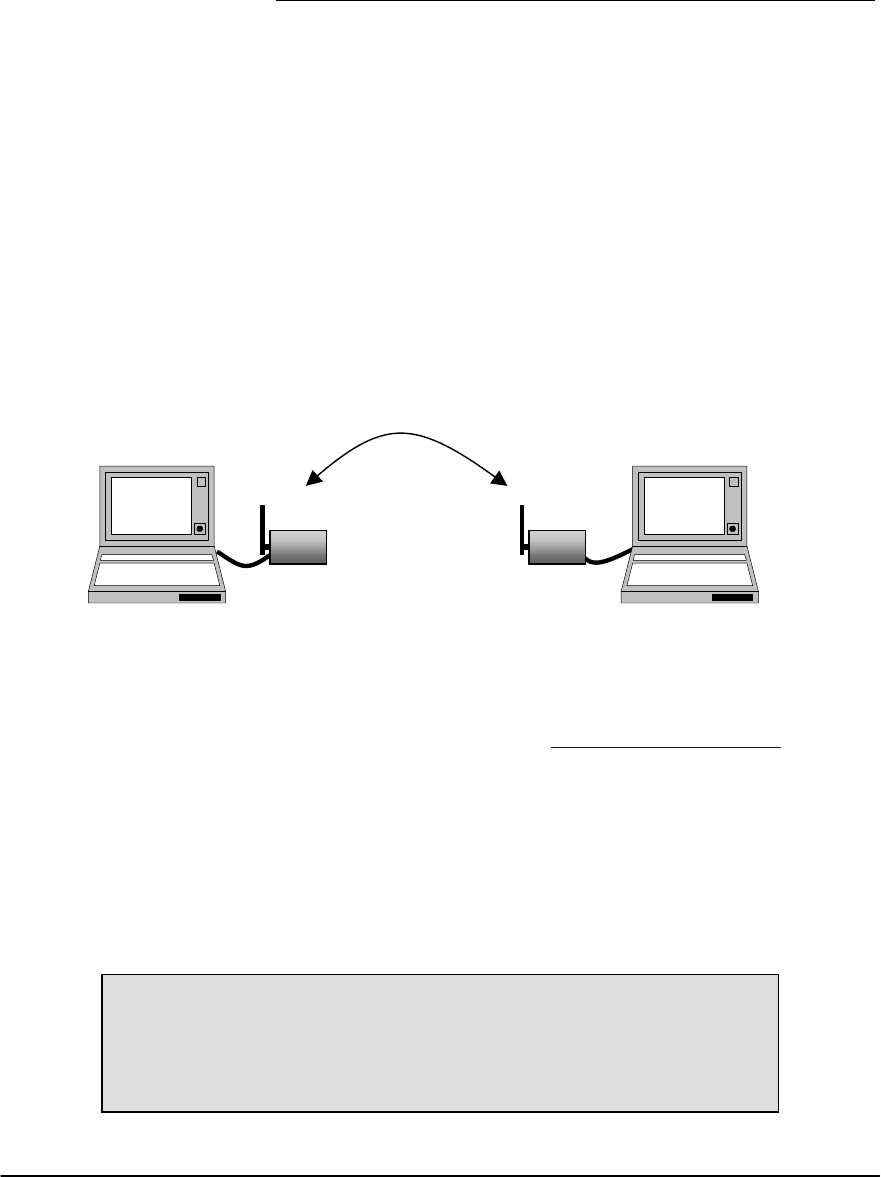
access the Internet via a networked PC and a pair of PT-209G/219G as illustrated below:
Figure 4. A PC or an embedded system can access the Internet via a pair of Purpletooth® modems and
another PC with NDIS-USB driver installed.
In the recent release, the Windows 2000 and Windows XP versions of NDIS-USB driver are
provided. Please refer to “Purpletooth® Family USB Driver Installation Guide” for the installation
and usage details.
Slave
Master
Internet
PC with NDIS-USB
driver installed AND
an ordinary Ethernet
adapter connected to
Internet
PC or embedded
system with NDIS-
USB driver installed
LAN cable USB cables
Purpletooth Purpletooth
Wireless connection

7
PT-209G/219G
RF Frequency 2.400 to 2.4835 GHz, carrier at 2.4476 GHz
Spread Spectrum Direct Sequence (DSSS)
Processing Gain 11.4 – 17.4 dB
Antenna Dipole antenna (RO-IK-0504 from Radiall), 50 ohm
load /
*Magnet mount antenna (TQC-2400AIP from
Kenbotong Communication Ltd.) /
*Omni-directional antenna (HTQ-2.4-10 from Xian
Haitian Antenna Tech. Co., Ltd.)
Operating Range Up to 5 km (15 km for HTQ-2.4-10 antenna) in line-
of-sight
Maximum E.I.R.P. 100 mW (20 dBm)
Receiver Sensitivity -96 dBm at 10-6 BER
RF Channel Bandwidth 32 MHz (Null-to-null)
Communication Method Time division duplex (TDD)
Network Protocol Purpletooth® Adaptive Intelli-Polling
Error Control CRC and ARQ
Baseband Modulation BPSK and QPSK
Channel Data Rate 256 Kbps, 512 Kbps, Up to 1 Mbps
I/O Interface RS232, USB# and RJ-45 ports
Supply Voltage 12 V
Maximum Current Consumption 535 mA at 7.4 V during transmission
310 mA at 7.4 V during reception
85 mA at 7.4 V during sleep
Battery Rechargeable, 7.2V/1550mAh
Operating Temperature -20 oC to 70 oC, (-4 oF to 158 oF)
Humidity 20 % to 90 % non-condensing
Dimensions (L × W × H) 157 × 76 × 45 mm (without antenna)
Weight 512 g
*TQC-2400AIP and HTQ-2.4-10 are optional for US shipment only.
# USB port cannot be used in hazardous environment under UL/ATEX classifications.
A. Technical Specifications

8
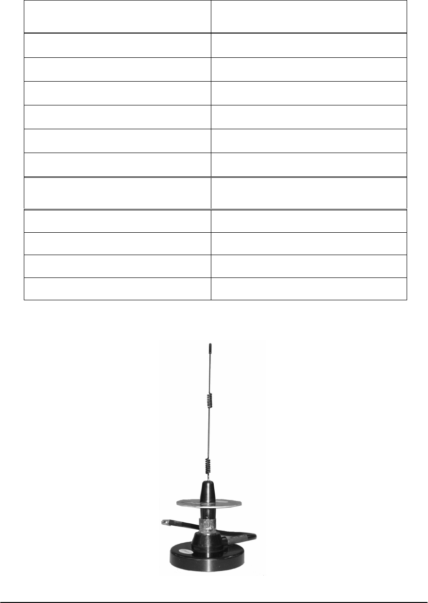
Model: RO-IK-0504
B. Antenna Specifications
Electrical Item Specifications Remarks
Type of antenna Dipole antenna
Frequency range 2.40 ~ 2.48 GHz
Electrical length 1 / 2 λ
Nominal impedance 50 Ohm
Polarization Vertical
V.S.W.R Less than 2.0
Peak gain 1.5 dBi
Mechanical Item Specifications Remarks
Element RG-316 cable
Sleeve Urethane Black
Base Nylon 66 Black
Connector SMA male Ni plate
Antenna total length 168 ± 3 mm
9
Model: TQC-2400AIP
* Manufacturer: Kenbotong Communication Ltd.
Electrical Item Specifications
Type of antenna Magnet mount antenna
Frequency range 2.400 ~ 2.483 GHz
Nominal impedance 50 Ohm
Polarization Vertical
V.S.W.R. Less than 1.5
Gain 7 dBi
Mechanical Item Specifications
Length 300 mm
Mount 90 mm diameter magnet
Cable 300 mm
Connector SMA male
10
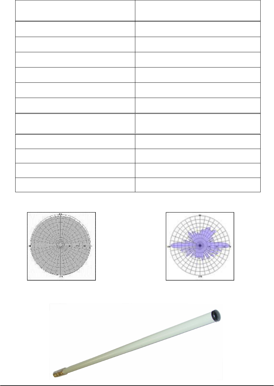
Model: HTQ-2.4-10
Antenna radiation pattern diagrams:
* Manufacturer: Xian Haitian Antenna Technologies Co., Ltd.
Electrical Item Specifications
Type of antenna Omni-directional antenna
Frequency range 2.400 ~ 2.500 GHz
Nominal impedance 50 Ohm
Polarization Vertical
V.S.W.R Less than 1.4
Gain 10 dBi
Mechanical Item Specifications
Length 824 mm
Diameter φ20 mm
Cable 500 mm
Connector SMA male
Horizontal direction Vertical direction