REnex Technology PT2400GS00-A Spread Spectrum Transmitter User Manual coRE3
REnex Technology Limited Spread Spectrum Transmitter coRE3
User Manual

REnex
Technology Ltd
ZcoRE3-2400
(ZcoRE3-2400/ZcoRE3(20)-2400)
OEM Serial Wireless Transceiver Module
User Manual
Version 1.0
May, 2007
This manual covers the operations of the ZcoRE3-2400 family of serial OEM wireless
transceiver modules. For the most part, operation of each product in the ZcoRE3-2400 family
is identical; where operating differences exist, every effort has been made to clearly identify
which product is being referred to.
This manual is produced for users of the ZcoRE3-2400 OEM wireless transceiver module
from REnex Technology Limited. It covers the operating principles and capabilities of the
ZcoRE3-2400 module. It is recommended that you read this document before using the
ZcoRE3-2400 module in order to operate it correctly and optimize its performance.
WARRANTY
REnex Technology’s ZcoRE3-2400 module is warranted against defect in
materials and manufacturing for a period of two years from date of
purchase. In the event of a product failure due to materials or workmanship,
REnex will, at its discretion, repair or replace the product. REnex and its
suppliers shall in no event be liable for any damages arising from the use
of or inability to use this product. This includes business interruption, loss
of business information, or other loss which may arise from the use of the
product.
WARNING
Changes or modifications to this unit not expressly approved by the party
responsible for compliance could void the user’s authority to operate the
equipment.
REMINDING
This device complies with Part 15 of the FCC Rules. Operation is subject to
the following two conditions: (1) this device may not cause harmful
interference, and (2) this device must accept any interference received,
including interference that may cause undesired operation.
While using for ZcoRE3(20)-2400, precaution below is necessary:
PRECAUTION
1. The installed antenna must not be located in a manner that allows
exposure of the general population at a distance of less than 4cm.
2. Mount the antenna in a manner that prevents any personnel from
entering the area within 4cm from the central position of the antenna.
3. It is recommended that the installer place radio frequency hazard
warnings signs on the barrier that prevents access to the antenna.
4. Prior to installing the antenna to the antenna connector, make sure the
power is adjusted to the settings specified in section of this manual.
5. During antenna installation, be sure that the power to the equipment is
turned off in order to prevent any energy presence on the coaxial
connector.
This manual contains information of proprietary interest to REnex Technology Limited. It has
been supplied in confidence to purchasers and other authorized users of the ZcoRE3-2400
module, and by accepting this material, the recipient agrees that no part of the document
shall be reproduced or transmitted in any form or by any means, without prior written consent
of REnex Technology Limited.
Information in this document is subject to change without notice.
REnex Reference Number:
Print Date: Feb. 2007
© 2006-2010 REnex Technology Limited. All rights reserved.
Microsoft and Windows are registered trademarks of Microsoft Corporation.
HyperTerminal is copyrighted by Hilgraeve Inc, and developed for Microsoft.
All other products mentioned in this document are trademarks or registered trademarks of their respective
holders.

ZcoRE3-2400_User_Manual_V1.0
Document Version History:
Version Release Date Comment
V1.0 Feb 28,2007 Initial Release
V1.1 May 18 2007 Updating for Approval
iii

ZcoRE3-2400_User_Manual_V1.0
Table of Content
1. Introduction...............................................................................................................................1
2. Technical Parameters ................................................................................................................2
3. Module Interface.......................................................................................................................3
3.1 1.27 mm Pin Header Interface.......................................................................................3
3.2 RF Interface...................................................................................................................6
3.3 RMCI interface..............................................................................................................7
3.4 Wakeup..........................................................................................................................8
4. Power Supply ............................................................................................................................8
5. Module Configuration...............................................................................................................8
6. RAEMESH Module Command Interface (RMCI)..................................................................11
6.1.1 Serial port setting ............................................................................................ 11
6.1.2 Package format................................................................................................11
6.1.3 Quick review of RMCI....................................................................................12
7. Mechanical Drawing ...............................................................................................................17
7.1 Top View .....................................................................................................................17
7.2 Bottom (top perspective).............................................................................................18
8. Order Information ...................................................................................................................19
iv

ZcoRE3-2400_User_Manual_V1.0
Terms:
Coordinator:
A FFD used for gateway. Only one coordinator per network.
FFD:
Full Function Device. Sensor node with routing ability. FFD requires line power all time.
RFD:
Reduce Function Device. A Sleeping node can only talk to a FFD or Coordinator. Can not relay
the message. Can be a battery powered device.
RCM:
Radio Communications Module
RDTE:
Reader Data Terminal Equipment.
SDTE:
Sensor Data Terminal Equipment.
RMCI:
RAEMESH Module Command Interface.
RCM:
Radio Frequency Communication Module, ZcoRE3-2400/ZcoRE3(20)-2400 OEM module
v

ZcoRE3-2400_User_Manual_V1.0
Introduction 1.
The ZcoRE3-2400 serial OEM transceiver module is a small size, high performance wireless
module, which is designed to provide a cost efficient solution for reliable data transmission and
low power consumption. It is ideal for low data rate wireless applications, including sensor
monitoring, building automation, security systems and any other application requiring low power
consumption. The ZcoRE3-2400 module family includes devices that work at two different RF
power, including 0dBm and 18dBm, to enable license-free operations in varies applications.
The ZcoRE3-2400 module offers data communication capabilities to application equipment
via a standard UART interface. Using a pair of ZcoRE3-2400 wireless modules, users can transfer
data between almost any type of equipment that use this interface.
The ZcoRE3-2400 module provides two power modes, normal working mode and sleep
mode, which has very low power consumption since the device can neither transmit nor receive
data in this mode. Switching to sleep mode whenever possible generally creates significant energy
savings, which is important for battery-powered systems.
These modules are preloaded wireless sensor mesh network application (RAEMESH), which
was developed based on EmberZnet 2.23 mesh stack. This documentation also describes the
RAEMESH Module Command Interface (RMCI) for IEEE 802.15.4/Zigbee enabled RF Module
(RCM), Including ZcoRE3 (20)-2400 and ZcoRE3-2400.
By using RMCI, users can easily integrate the mesh radio into a wide range of applications
without pain to develop the mesh stack by themselves and no RF expertise is required.
Features of ZcoRE3-2400:
y Mesh network
y ISM frequency bands – 2.4 GHz ~ 2.4835GH
y High receiver sensitivity - superior transmission range for a given RF power
y Designed to hazardous industrial requirements - may be used in instruments certified for
intrinsic safety operation
y Low power consumption - conserves battery power
y Small size, light weight - easy to integrate
y Low cost - cost-efficient systems
Application examples:
y Smart badges
y Remote monitoring and control
y Perimeter security/access control
y Medical instrumentation
y Environmental monitoring
y Sensor networks
y Diagnostic monitoring
y Industrial telemetry
y Automatic meter reading
y …
1
ZcoRE3-2400_User_Manual_V1.0
Technical Parameters 2.
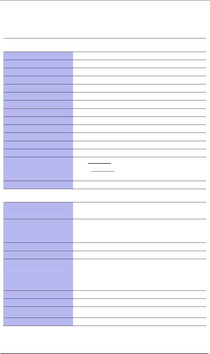
Table 2.1 Technical Parameters of ZcoRE3-2400/ZcoRE3(20)-2400
Radio Characteristics
RF Frequency Band 2.4 ~ 2.4835GHz
Number of Channels 16 channels
Channel Spacing 5 MHz
RF Data Rate 250 kbps
Modulation OQPSK
Duplex TDD
Maximum E.R.P. 1 (0 dBm) ~ 60 mW (18 dBm)
Receiver Sensitivity -95 dBm at 10-3 BER
Receiver Classification Class 2
Operating Range Up to 1 km in line-of-sight(18dBm)*
Network Protocol Zigbee & IEEE 802.15.4 compliant
Operating Mode Mesh
Error Detection CRC and ARQ
Radio Type Approval
CE: EN300-328
FCC: Part 15.247
SRRC & Middle-East : (pending)
Intrinsic Safety Design UL C1D1 / ATEX T4
Miscellaneous
I/O Interface Serial TTL with universal socket: 2 x 20 pins with 1.27 mm
I/O Option
Two digital I/O; one analog I/O;
RS-232(TTL) for optional modules (Bluetooth, GPS, GPRS and
WiFi)
Antenna Port Interface Chip antenna(0dBm,18dBm)/MMCX female(18dBm)
Power Supply 3.3 ±.3V
Power Consumption
Normal working mode:
Tx: 44 mA | 230mA(18dBm)@ 3.3 V
Rx: 35 mA | 35mA(18dBm)@ 3.3 V
Sleep mode: 9 uA | 9 uA(18dBm) @ 3.3 V
Operating Temperature -40o C to 75o C
Humidity 20% to 90% non-condensing
Dimensions (L × W × H) 46.5 mm x 26 mm x 10 mm
Weight 10 grams (0.35 ounce)
*Depending on the interference environment.
2
ZcoRE3-2400_User_Manual_V1.0
Module Interface 3.
3.1
The module interface includes the power input (3.3 V), power output (3.3 V), configuration
button signal, serial ports (CMOS 3.3 V), A/D, I2C, test signal, JTAG and digital I/O, etc. These
are integrated on a dual row, 20 pins per row, 1.27 mm pitch connector (J1). Refer to Table 3.1
for a detailed pin definition.
REnex can provide an evaluation kit for the ZcoRE3-2400/ZcoRE3 (20)-2400 module, which
includes 4 modules and 4 evaluation mother board (refer to the ZcoRE3-2400 evaluation kit user
manual for more details). The module interface and other important IO are provided on the
module evaluation board.
The users can also design their own application board with the required module interface. Two of
the most important interfaces are the pin header interface and the RF interface described below.
1.27 mm Pin Header Interface
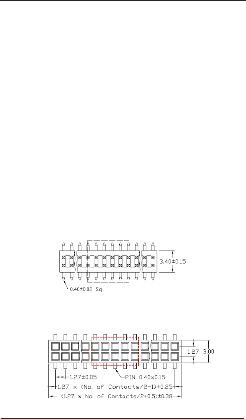
The pin header interface of the ZcoRE3-2400/ZcoRE3(20)-2400 is designed using a dual row
1.27 mm socket with a total of 40 pins. The JVE 21N21040-40M00B-01G-2.2/5.8 will be
mounted on when the module is shipped. Refer to the JVE datasheet for detailed socket
information.
Users that want to use a different socket can also request that the pin header is not mounted.
These users must make sure to match the PCB design of the interface. The following is a general
drawing of the JVE socket (dimensions in mm).
To match the ZcoRE3-2400/ZcoRE3(20)-2400 interface using the JVE pin header, JVE
22p8702-40M00B-01G-4.5 is an appropriate housing. The following is a general drawing of the
JVE housing (dimensions in mm).
3

ZcoRE3-2400_User_Manual_V1.0
The pin definition of the header interface is shown on Table 3.1; the input and output description is
based on module side. The main serial port is port 1 which includes TxD1 (pin 5) and RxD1 (pin
7). It will be set as the default port in the factory. There are three UART ports which can be used
on the module.
Pin 3 (RST) is the reset input; the module will reset if a low level signal is input.
The ZcoRE3-2400/ZcoRE3(20)-2400 module provides RFD two power modes, wakeup and sleep
mode. In wakeup mode, the module can execute normal operations, transmit and receive data via
the RF channel. A low level input on Pin 19 will put the RFD module enter sleep mode.
Pin 17, 28 and 30 can be used for temperature or battery voltage detecting input.
Pins 27, 32, 34, 36, 38 are reserved for In-System Programming (ISP), and also for firmware
debugging. All these pins are dedicated to JTAG and cannot be used for any other IO functions.
4

ZcoRE3-2400_User_Manual_V1.0
Table 3.1: Pin Definition of J1
Pin Function IN/OUT Description Remark
1 GND COMM Ground
2 GND COMM Ground
3 RST IN Reset signal input External reset, active low
4 GND COMM Ground
5 TxD1 OUT UART1, transmit data Default serial port
6 TxD0 OUT UART0, transmit data
7 RxD1 IN UART1, receive data Default serial port
8 RxD0 IN UART0, receive data
9 GPIO0 IN&OUT General IO
10 LED_2 OUT LED control signal Connect to LED for debugging
11 GPIO1 IN&OUT General IO
12 LED_3 OUT LED control signal Connect to LED for debugging
13 GPIO2 IN&OUT General IO
14 LED_4 OUT LED control signal Connect to LED for debugging
15 GPIO3 IN&OUT General IO
16 LED_5 OUT LED control signal Connect to LED for debugging
17 TEMP_EN_GPIO4 IN&OUT Temperature /GPIO Temperature Enable (active high)
18 PS_CS IN Reserved, PACKET_TRACE_CS
19 GPIO5 IN Reserved,
20 PS_FRAME IN Reserved, PACKET_TRACE_FRAME
21 BUZZER_GPIO6 IN&OUT Buzzer or General IO
22 3.3V_Vout OUT 3.3V output External power output, 20mA max
23 PS_DIR_GPIO7 IN&OUT General IO PACKET_TRACE_DIR
24 GND COMM Ground
25 BUTTON_0_GPIO8 IN&OUT Button 0 input/GPIO
26 AREF OUT Reserved, Reference level output
27 BUTTON_1_GPIO9 IN Button 1 input/GPIO
28 ATEMP_ADC1 IN&OUT General IO/ADC1 Battery pack voltage input
29 DBG_SYNC_GPIO10 OUT RF debug/GPIO10
30 ADC2 OUT ADC2 Temperature calibration
31 RF_SO OUT Reserved, RF testing points
32 JTCK IN Reserved, JTAG, common clock
33 RF_SI IN Reserved, RF testing points
34 JTMS IN Reserved, JTAG, mode selection
35 RF_SCLK IN Reserved, RF testing points
36 JTDO OUT Reserved, JTAG, serial data out of service
37 RF_SFD IN Reserved, RF testing points
38 JTDI IN Reserved, JTAG, serial data into service
39 3.3Vin IN 3.3V, power input
40 3.3Vin IN 3.3V, power input
5
ZcoRE3-2400_User_Manual_V1.0
3.2 RF Interface
Different RF interfaces are provided on the ZcoRE3-2400 module.
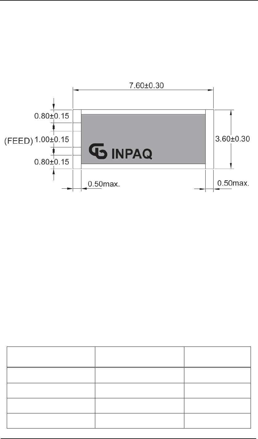
For the ZcoRE3-2400 module, only a chip antenna can be soldered on when the modem ship out.
Refer to diagram below for detail information of chip antenna.
For the ZcoRE3(20)-2400 module, only the external antenna is available. P1 (refer to mechanical
drawing) is designed on PCB board for the reversed SMA antenna connection via a special RF
cable. The socket is user a right-angle straight MMCX (Miniature Microax RF Coaxial)
connector which can be soldered on the top of PCB when the module is delivered. The maximum
height of the MMCX socket is less than 4 mm. If customer would like to use a different socket,
they may also elect not to have the MMCX socket soldered on. In that case, they should be sure
to match the PCB design of the socket.
To connect with the SMA antenna, a MMCX-to-SMA converter RF cable is provided together
with the ZcoRE3(20)-2400 module as option.
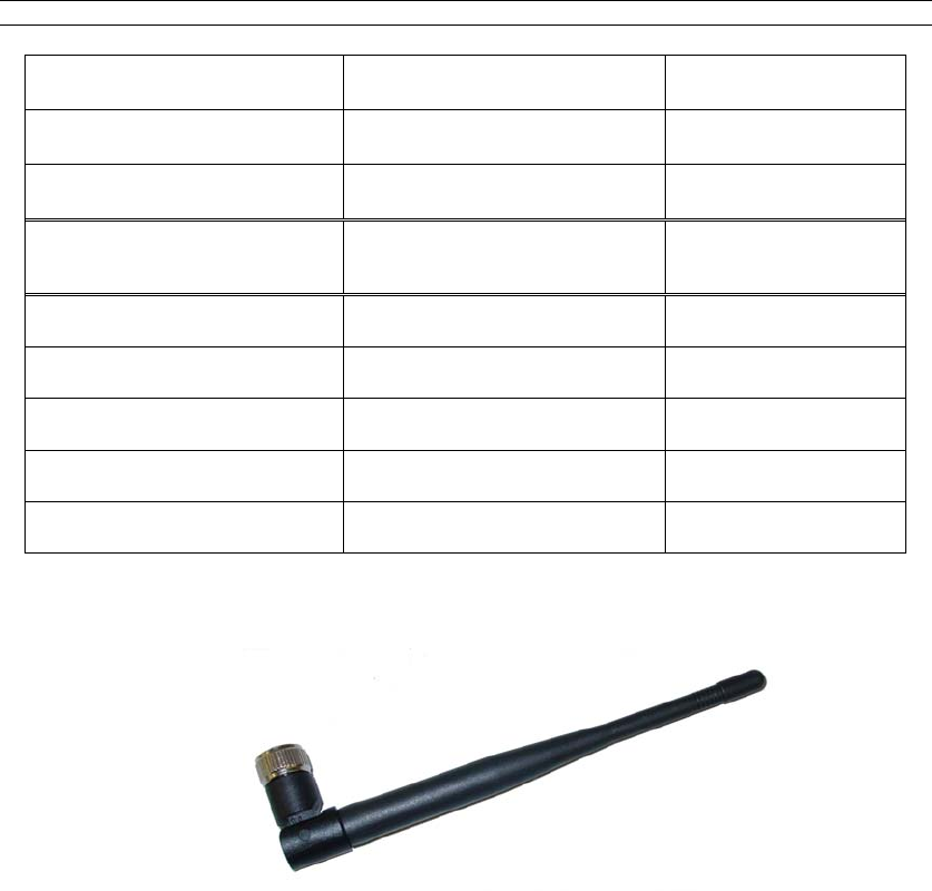
Refer to table and picture below for detail information of SMA antenna.
Model: RO-IK-0504
Electrical Item Specifications Remarks
Type of antenna Dipole antenna
Frequency range 2.40 ~ 2.48 GHz
Electrical length 1 / 2 λ
Nominal impedance 50 Ohm
6
Polarization Vertical
V.S.W.R Less than 2.0
Peak gain 1.5 dBi
Mechanical Item Specifications Remarks
Element RG-316 cable
Sleeve Urethane Black
Base Nylon 66 Black
Connector SMA male Ni plate
Antenna total length 168 ± 3 mm
RMCI interface 3.3
The module is pre-loaded with the EmberZnet bootloader (version:1005), which supports both
over-the-air bootloading and serial bootloading of firmware update. The module contains
RAEMESH application developed base on EmberZnet stack 2.23 and comply with the RAE
System’s RCS protocol. The module also has built-in RAEMESH Module Command Interface
(RMCI). Section 6 is focused on the instruction on RMCI interface.
The RMCI command interface allows customer to easily access to low level mesh functionality
without pain to develop the firmware. The module can be configured to a coordinator to hook up
to a getaway or just a standalone regular full function node or a sleepy reduce function node.
Make sure to configure the module to right mode before using.
7

ZcoRE3-2400_User_Manual_V1.0
Wakeup 3.4
4.
5.
If the radio is set to RFD mode, the Wakeup pin Pin19 is used to make the radio asleep and
wakeup. A constant high on this pin will make the radio go to the sleep mode and a low level
signal on this pin will wake-up the radio.
The Radio sleep mode is the power save mode with very low power consumption. (<60uA)
The Wakeup pin must be held up to 10ms before sending a data packet.
Power Supply
As OEM module, the power supply should be provided by the main equipment, in which the
OEM module is built. Normally, a 3.0 ~ 3.6V DC power is required.
Module Configuration
Enter Configuration Status
Via the TXD and RXD pins the command interpreter can be accessed. The RCM can buffer up to
128 bytes of incoming data in a software FIFO buffer and uses XON/XOFF flow control. See the
datasheet of the Atmel Atmega 128L for more information about the build-in UART. Connect
Pin5 (TXD1) and Pin7 ( RXD1) to the customer board. Use the following settings for serial port.
Coordinator FFD and RFD
Bits per second 19,200 19,200
Data bits 8 8
Parity check None None
Stop bits 1 1
Flow control None None
PC communication
Confirm that the serial port debugging software is installed on the PC. For example:
sscom32.exe. Microsoft Hyper Terminal is not recommended for this application because it is not
good to send characters and commands in Hex.
Data packet
RCM will transmit any data in the { }, and all data in the {} will be transparently sent out
without radio’s interpretation. The maximum data packet is 50 bytes including {}.
The data in the {} can be any characters including ‘{’, ‘}’, ‘[’and ‘]’.
The interval between two data packets must be >50 ms for FFD and coordinator.
The interval between two data packets must be >1 s for RFD.
For old RAEWATCH_PSP
8

When the sensor node sends data to gateway, the gateway will receive the data plus the last four
digits of sensor node ID in the {}. When the gateway sends data to sensor node, the sensor node
radio will only receive data in the {}.
For RAEWATCH_RCS
The data in the {} will be untouched by either gateway or sensor node. You get what you send.
For RCS details, refer to: 904-E800-120 RAEWATCH WSN Communication Standard.doc
9

ZcoRE3-2400_User_Manual_V1.0
Base on correct setting and connection, you will see following display on your screen when
power is applied.
Coordinator:
EVENT: emberInit passed
INIT: sink app 000D6F0000002DF8 chan:0x1A, pwr:FF, panID:0x30FF
EVENT: stack Status now EMBER_NETWORK_UP
EVENT: setting multicast binding, status is 0x00
FFD:
EVENT: emberInit passed
FFD SENSOR APP: joined to network
000D6F0000002DA5 chan:0x1A, pwr:FF, panID:0x30FF
EVENT: stack Status now EMBER_NETWORK_UP
EVENT: setting multicast binding, status is 0x00
This is a free sensor.
RFD (if there is a coordinator or FFD)
EVENT: emberInit passed
RFD Sleep SENSOR APP: joined to network
000D6F0000002DA5 chan:0x1A, pwr:FF, panID:0x30FF
EVENT: stack Status now EMBER_NETWORK_UP
EVENT: setting multicast binding, status is 0x00
This is a free sensor.
RFD (if there is no coordinator or FFD)
EVENT: emberInit passed
RFD Sleep SENSOR APP: joined to network
000D6F0000002DA5 chan:0x1A, pwr:FF, panID:0x30FF
EVENT: stackStatus now MOVE_FAILED. Lost the Parent (Coordinator)
10
ZcoRE3-2400_User_Manual_V1.0
6. RAEMESH Module Command Interface (RMCI)
Serial port setting 6.1.1
6.1.2
Between RDTE and RRCM: 38400 bps, 8N1
Between SDTE and SRCM: 19200 bps, 8N1
Package format
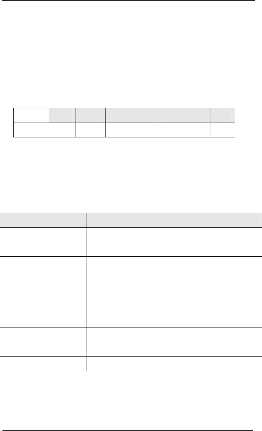
Packet format as listed below:
SOP Length Command Code Command Data EOP
Byte 1 1 1 0~n 1
z The minimum length for one packet is 4 bytes long. The Length is 0x20 based. E.g. the total
length of a packet without command data is 4, the Length byte is 0x20 + 4 = 0x24.
z The SDTE or RDTE always initiate the communication with Radio module (RRCM,
SRCM). Radio module responses to the command it received.
z The Command Code for packet sent from SDTE or RDTE to Radio module is even, the
response from Radio module to SDTE or RDTE is 1 higher than the command code.
z Command Data can be empty.
Table 5.1: Byte definition of packet
Byte Number Name Comment
0 SOP Radio Protocol beginning of packet. This is always ‘[’ (0x5B)
1 Length Total length of packet + 0x20, include ‘[’ and ‘]’.
2 Command Code 0x20 ~ 0xFF.
**Excluding: 0x5A~0x5F and 0x7A~0x7F.
**0xF0~0xFF are reserved for common commands such as help, version etc.
Even for packet sent from SDTE or RDTE to RCM.
Odd for packet response from RCM to SDTE or RDTE.
3 Command Data Hex
… … …
N+3 EOP Radio protocol end of packet. This is always ‘]’ (0x5D).
Notes:
1. Always perform a Network Joining for FFD before using it. A coordinator must be
presented when perform the network joining. Command: 5B24505D.
2. Check RCM’s information when turn on the radio. Command: 5B24605D.
3. Wait at least 5s for RCM to finish the initialization.
11

ZcoRE3-2400_User_Manual_V1.0
4. Check the Network Status of the RFD before sending the data at the first time. Command:
5B24205D.
5. It is recommend 1s interval between two data packets for RFD. Check [] for sending
acknowledge in Unicast mode. There is no ACK for multicast mode.
6. For RFD, if there is no network, the RCM will automatically wake up every 1 minute to
search for a new network. It can be interrupted at any time. RCM will keep in asleep if it
has joined a network.
7. For debug purpose, check network status and Parent ID of RFD.
Quick review of RMCI 6.1.3
5b24205d = NETWORK_STATUS
5b24225d = GET_BINDING_LIST
5b24245d = SYSCH_ADVERTISE
5b2526XX5d = COM_UNICAST_RID. XX is the radio index
5b24285d = DEL_RMT_BINDING
5b242c5d = COM_MULTI_RID
5b24305d = GATEWAY_ENABLE. Enable Coordinator function.
5b24325d = FFD_ENABLE. Enable Full Functional Device function as a Router.
5b2534XX5d = CHAN_RRCM_CHANNEL. XX is channel number (0x0B-0x1A).
5b2536XX5d = DEL_LOCAL_BINDING. XX is the binding index started from 1.
5b24385d = RPT_SENSOR_POSITION.
5b243E5d = LEAVE THE NETWORK.
5b24465d = RFD_ENABLE. Enable RFD function.
**PE7 High makes radio sleep.PE7 Low actives the radio.
5b24485d = SOFT_RST. Perform soft reset.
5b244A5d = RACTORY_RST. Restore the radio to factory setting.
5b244C5d = VERSION_CHK. Check the firmware version of the Radio.
5b244E5d = PRINT_TOKEN. Print stack and application tokens.
5b24505d = JOIN_FORM_NETWORK. Form (Gateway) or Join (Sensor) a new network.
5b24525d = MULTICAST_HELLO. Say HELLO to the world.
5b24545d = PRINT_CHILD_TABLE. Print Child table.
5b24565d = BOOT_LOADER. Launch the standalone boot loader.
5b24605d = GET_NODE_INFO. Get Radio's information like EUI, channel and PANID.
5b24625d = BUTTON_0_PRESS. Press Button 0.
5b24645d = BUTTON_1_PRESS. Press Button 1.
5b2566xx5d = SET_PROTOCOL. Set communication protocol.
**RAEWATCH: 0, RCS: 1, Transparent: 2.
5b24685d = GET_PARENT_ID. Get the parent ID for RFD.
5b24705d = JIT_MSG_STATUS. Just In Time Message Status.
5b24F05d = HELP
5b24F25d = PRINT ASCII BINDING TABLE.
5b2CF4xxxx0000006F0D005d = Pass the image to remote node through the Gateway.
5b2CF6xxxx0000006F0D005d = Clone the Gateway image to a remote node.
12

Command Name
CMD
Code
CMD Data
(bytes)
Response
CMD Code
Response CMD
Data (Bytes)
Description
NETWORK_STATUS
Use on:
Coordinator
FFD
RFD
0x20 None 0x21 STATUS(1) Return the radio’s network status
0x00: NO NETWORK
0x01: JOINING NETWORK
0x02: JOINED NETWORK
0x03: JOINED_NETWORK_NO_PARENT
0x04: LEAVING NETWORK
GET_BINDING_LIST
Use on:
Coordinator
FFD
RFD
0x22 None 0X23 Radio ID(8)
Radio Index(1)
For FFD and RFD: Radio return with bound target ID with index=0x00.
For Coordinator: Return bound node ID with index separately for each bound radio
nodes.
Start from 0 and up to 30.
*: Use this command after SYNCH_ADVERTISE.
SYNCH_ADVERTISE
Use on:
Coordinator
0x24 None 0X25 None Requests RCM to synchronize all radio nodes in the network to bind with the coordinator.
Nodes are in the Unicast mode after executing this command.
The maximum binding table size is 30 due to RAM limitation.
COM_UNICAST_RID
Use on: Coordinator
0x26 Radio index(1) 0X27 None. Requests RCM to send following data to specified radio nodes in Unicast mode per radio
index. Using datagram.
DEL_RMT_BINDING
Use on: Coordinator
0x28 None 0X29 None Requests RCM to send a delete binding command to all nodes in network. All nodes in the
network became to free nodes and will communicate in Multicast mode. RFD will not
respond this command.
COM_MULTI_RID
Use on: Coordinator
0x2C None 0X2D none Requests to go back to multicast mode after using COM_UNICAST_RID. All data after
this command will be broadcasted.
COOR_ENABLE
Use on: FFD/RFD
0x30 None 0x31 None Set the radio as a Coordinator so that the radio can be use on a Gateway device.
Baud rate change to 38400 8N1
13
Table 5.2.1: Detailed information of RMCI package

Table 5.2.2: Detailed information of RMCI package
Command Name
CMD
Code
CMD Data
(bytes)
Response
CMD Code
Response CMD
Data (Bytes)
Description
FFD_ENABLE
Use on: Coordinator/RFD
0x32 None 0x33 None Set radio to FFD. Always on and has router function.
CHG_RRCM_CHAN
Use on:
Coordinator
0x34 Channel
Number(1)
0x35 None Requests RCM in the Gateway to change its radio channel to specified channel.
0x0B to 0x1A total 15 channels.
Corresponding to 11 to 26 of IEEE 802.15.4.
DEL_LOCAL_BINDING
Use on:
Coordinator/FFD/RFD
0x36 Binding
index(1)
0x37 None Deletes binding indexes stored in the radio.
Binding index is from 1 to 30.
Always 1 for FFD and RFD
RPT_LOCATION
Use on: RFD
0x38 None 0x39 None Report RFD parent’s ID.
LEAVE_NETWORK
Use on: Coordinator/FFD/RFD
0x3E None 0x3F None Leave the current network
RFD_ENABLE
Use on: Coordinator/FFD
0x46 None 0x47 None Put a node into RFD. PE7 interrupt enable. Active low.
SOFT_RST 0x48 None 0x49 None Reset the radio
FACTORY_RST
Use on:
Coordinator/FFD/RFD
0x4A None 0x4B None Restore the RCM to factory defaults.
Channel: 0x1A, Power: 0xFF, PanID: 0x30FF Sensor Node FFD.
Baud rate: 19200 8N1
VERSION_CHK
Use on:
Coordinator/FFD/RFD
0x4C None 0x4D DS[0] = ‘V’
DS[1~n+1]
Firmware
Version [0~n]
Request Firmware Version. Return In ASCII.
e.g.: “ EZ2.23.0.0 ”
Send:5B244C5D
Return:5B 2E 4D 45 5A 32 2E 32 33 2E 30 2E 30 5D
14

Table 5.2.3: Detailed information of RMCI package
Command Name
CMD
Code
CMD Data
(bytes)
Response
CMD Code
Response CMD
Data (Bytes)
Description
PRINT_TOKEN
Use on: Coordinator/FFD/RFD
0x4E None 0x4F Print radio’s Token information in ASCII.
For PC debug
JION_FORM_NETWORK
Use on:
Coordinator/FFD/RFD
0x50 None 0x51 None Coordinator:
Form a network to allow the other nodes to join.
FFD/RFD:
Search the network and try to join the network.
MULTICAST_HELLO
Use on: Coordinator/FFDRFD
0x52 None 0x53 None Broadcast a “hello” to entire network
PRINT_CHILD_TABLE
Use on: Coordinator/FFD
0x54 None 0x55 None Print the child table in ASCII
BOOT_LOAD
Use on: Coordinator
0x56 None 0x57 none Start the bootloader to download the radio application
GET_NODE_INFO
Use on:
Coordinator/FFD/RFD
0x60 None 0x61 Radio ID(8)
Channel(1)
Power(1)
PAN ID(2)
Get the node information: EUI, Channel, Power, PAN ID,
Send: 5B24605D
Return:
5B 30 61 00 0D 6F 00 00 00 2D A5 1A FF 30 FF 5D
BUTTON_0_PRESS
Use on: Coordinator/FFD/RFD
0x62 None 0x63 None Simulate Button Zero pressed
BUTTON_1_PRESS
Use on: Coordinator/FFD/RFD
0x64 None 0x65 None Simulate Button One Pressed
SET_PROTOCOL
Use on: Coordinator/FFD/RFD
0x66 Protocol(1) 0x67 None Set radio’s protocol
0x00: RAEWATCH_PSP.(old version) 0x01: RAEWATCH_RCS. 0x02: Transparent Mode.
15

Table 5.2.4: Detailed information of RMCI package
Command Name
CMD
Code
CMD Data
(bytes)
Response
CMD Code
Response CMD
Data (Bytes)
Description
GET_PARENT_ID
Use on:
RFD
0x68 None 0x69 Parent radio
ID(8)
Get the parent ID for RFD
Return:
5B 2C 69 00 0D 6F 00 00 00 2E CB 5D
if no parent, return
5B 2C 69 00 00 00 00 00 00 00 00 5D
HELP
Use on: Coordinator/FFD/RFD
0xF0 None 0xA1 None List all RMCI commands in ASCII
PRINT_BINDING_TABLE
Use on: Coordinator/FFD/RFD
0xF2 None 0xA3 None List all bindings in a table in ASCII
BOOTLOAD_PASSTHROUGH
Use on: Coordinator
0xF4 Remote Radio
ID(8)
0xF5 None Bootload remote node in pass through mode.
BOOTLOAD_CLONE
Use on: Coordinator
0xF6 Remote Radio
ID(8)
0xF7 None Bootload remote node and update the firmware in clone mode. Fast way.
16
7.
17
ZcoRE3-2400_User_Manual_V1.0
7.1
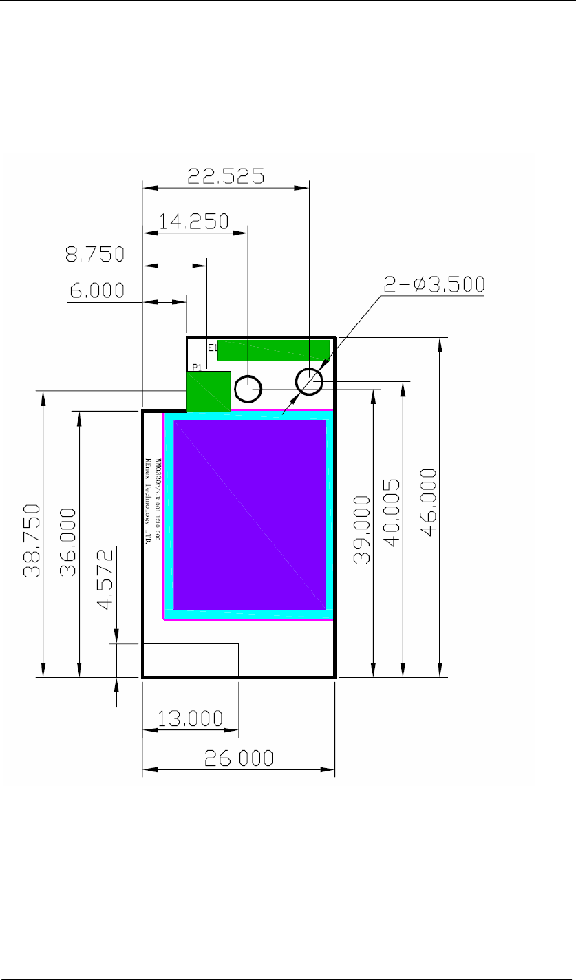
3: The height of the shield box on the top layer is less than 4.3mm from PCB board.
2: P1 is the MMCX connector for SMA antenna (connect via an MMCX-SMA RF cable)
and available only in ZcoRE3(20)-2400.
1: E1 is for the chip antenna and available only in ZcoRE3-2400. The length of the chip
antenna is less than 7.3mm
Note:
Mechanical Drawing
Top View
Units: mm
ZcoRE3-2400_User_Manual_V1.0
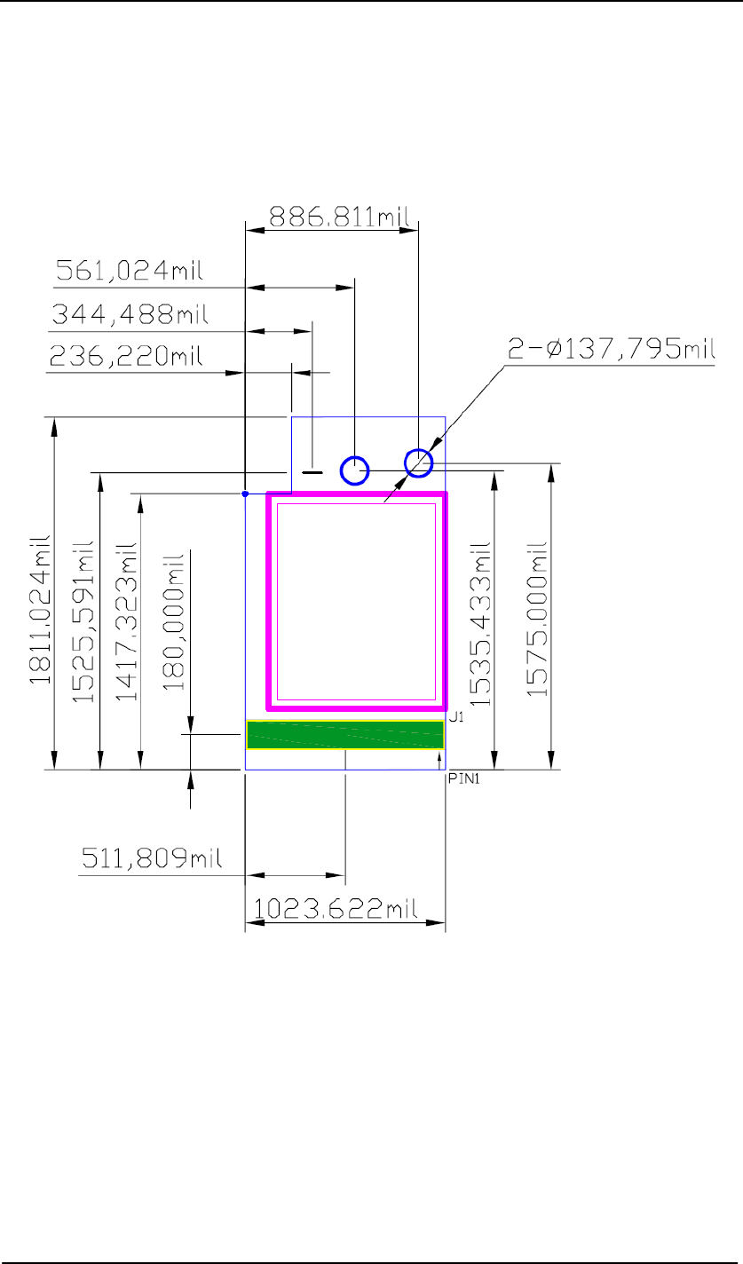
7.2 Bottom (top perspective)
Units: mil
Note:
1. J1 is the application and power supply interface (1.27mm pin header) which can be used for
board-to-board connection. Pay attention to the direction of socket.
2. There are two holes on board revered for modem fixing.
18
ZcoRE3-2400_User_Manual_V1.0
8. Order Information
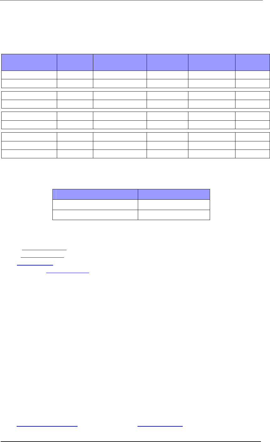
REnex provide series of ZcoRE3 OEM module that vary in RF output power and frequency as
well as standalone modems to cover a variety of application in different countries and regions.
Products RF Power Dimension RF
Regulation
Intrinsic
Safety
Type
ZcoRE3-2400 0 dBm 46.5 x 26 x 10 mm Worldwide C1D1/ATEX(T4) OEM
ZcoRE3(20)-2400 18 dBm 46.5 x 26 x 10 mm worldwide C1D1/ATEX(T4) OEM
ZcoRE3-868* 0 dBm 46.5 x 26 x 10 mm Europe ATEX(T4) OEM
ZcoRE3(20)-868* 18 dBm 46.5 x 26 x 10 mm Europe ATEX(T4) OEM
ZcoRE3-915* 0 dBm 46.5 x 26 x 10 mm USA C1D1 OEM
ZcoRE3(20)-915* 18 dBm 46.5 x 26 x 10 mm USA C1D1 OEM
REmesh-2400* 18 dBm TBD Worldwide - Standalone
REmesh-868* 18 dBm TBD Europe - Standalone
REmesh-915* 18 dBm TBD USA - Standalone
*Available in 2007
Product Ordering Information for the ZcoRE3-2400 series:
Products Part Number of REnex
ZcoRE3 -2400 R-001-0003-410
ZcoRE3(20) -2400 R-001-0003-400
Reference:
Ember: www.ember.com
Atmel: www.atmel.com
FCC: www.gcc.gov
Zigbee Alliance: www.zigbee.org
Disclaimer
Product and Company names and logos referenced may either be trademarks or registered
trademarks of their respective companies. We reserve the right to make modifications and/or
improvements without prior notification. All information is correct at time of issue. REnex does
not convey any license under its patent rights or assume any responsibility for the use of the
described product.
REnex Technology (ShangHai) Limited
Room C3-2, 3/F, No33
FuHua Road, JiaDing, Shanghai, China
Tel: 86-021-59902255 Fax: 86-021-59902211
Email: Sales@renextechnology.com
www.renextech.com
REnex Technology Limited
Room 608, 6/F., Hong Leong Plaza,
33 Lok Yip Road, Fanling, N.T., Hong Kong
Tel: 852-2607-4088 Fax: 852-2669-0803
Email: Sales@renextechnology.com
www.renextechnology.com
19