RF Code Z Humidity-Temperature Tag User Manual
RF Code, Inc. Humidity-Temperature Tag
User manual
Navigation menu
Upload a User Manual
Namespaces
Wiki Guide
HTML
PDF
Info
Views
User Manual
Discussion / Help
Navigation
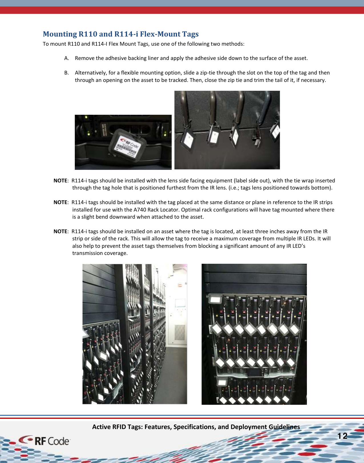
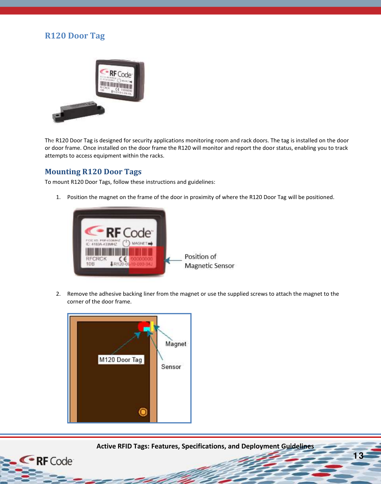
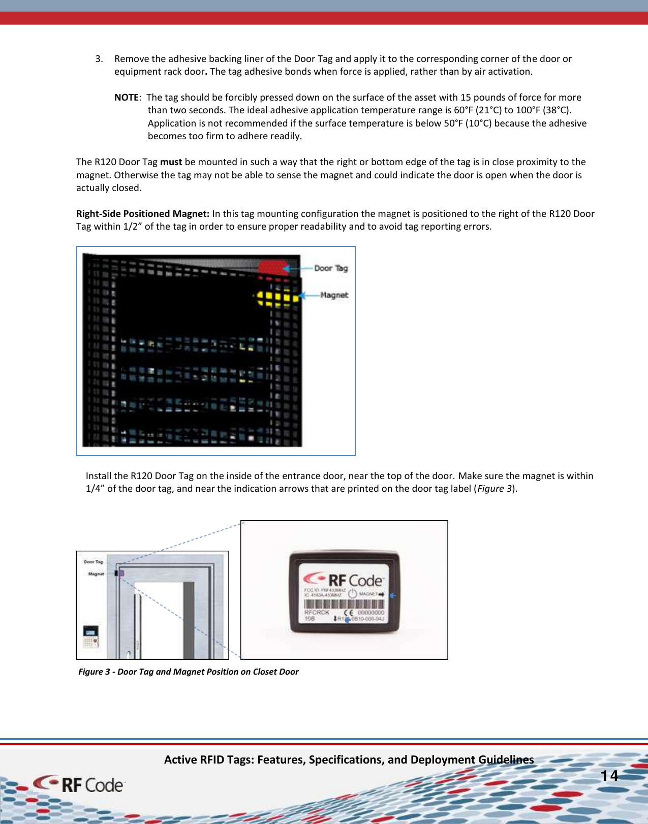
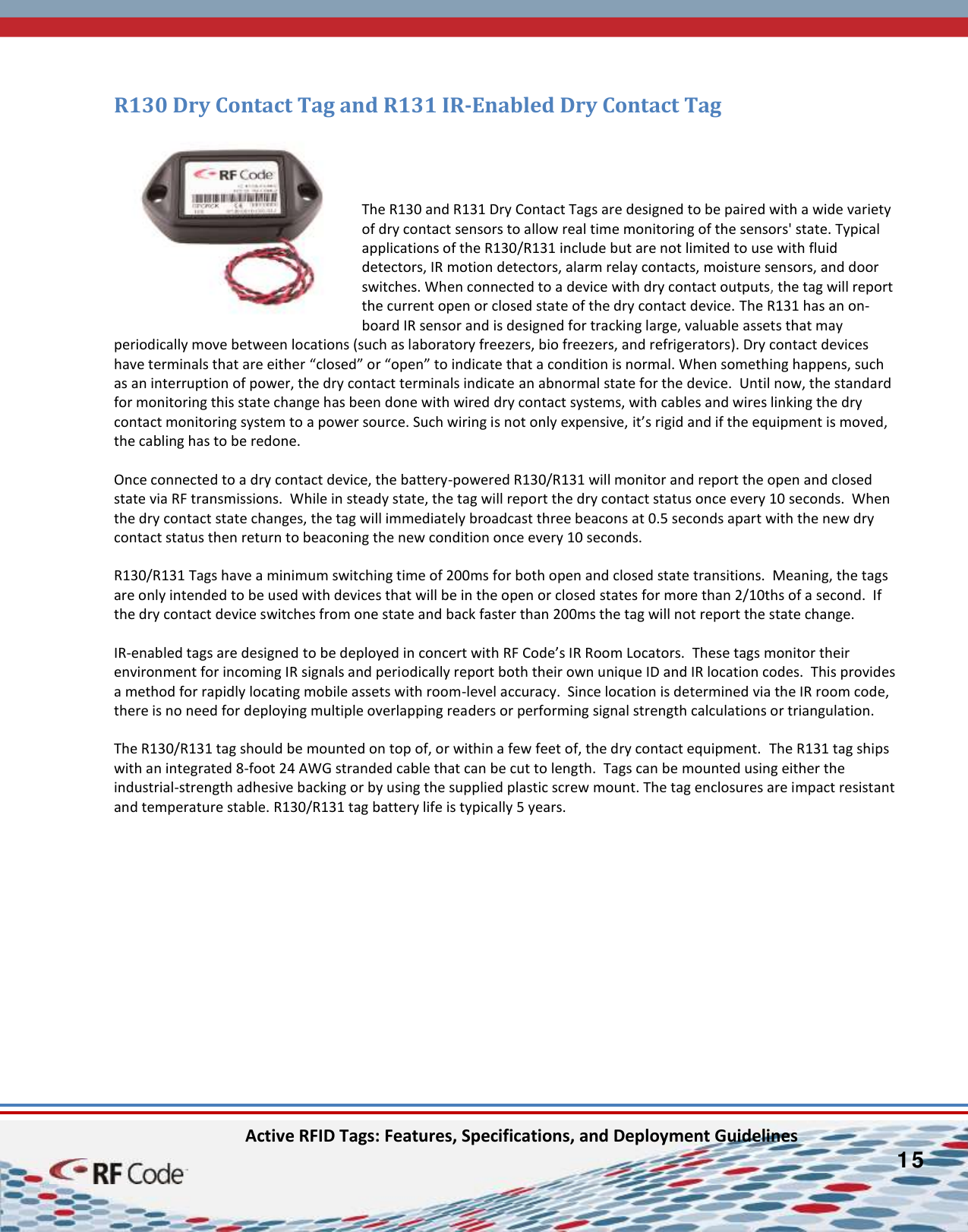
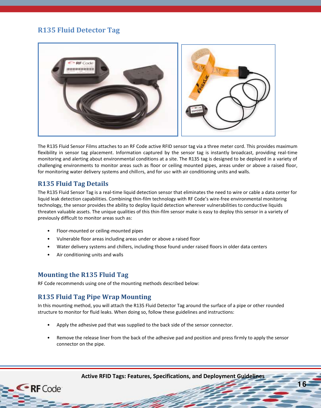
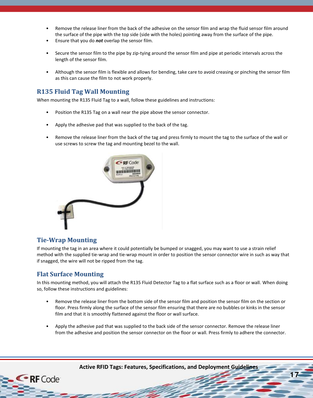
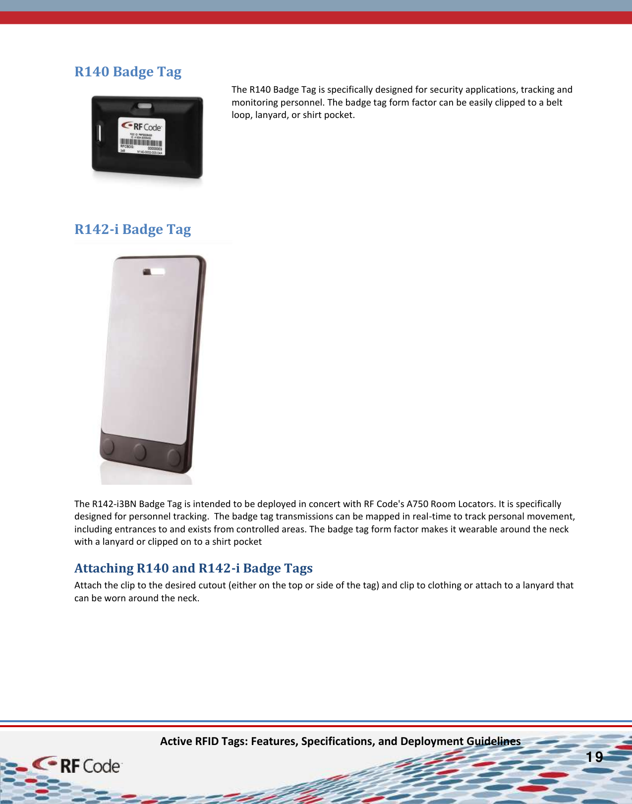
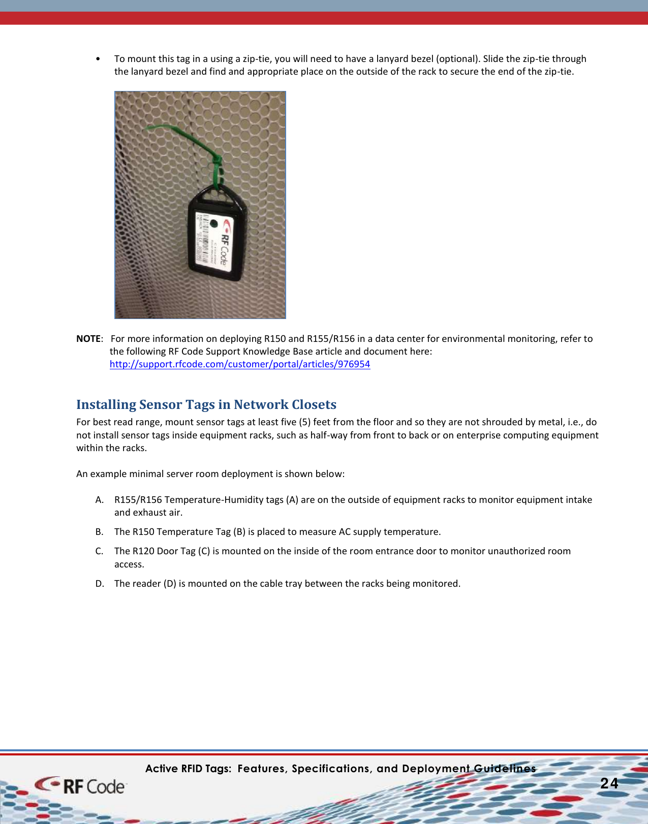
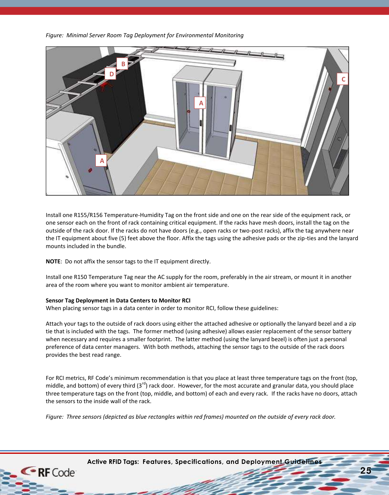
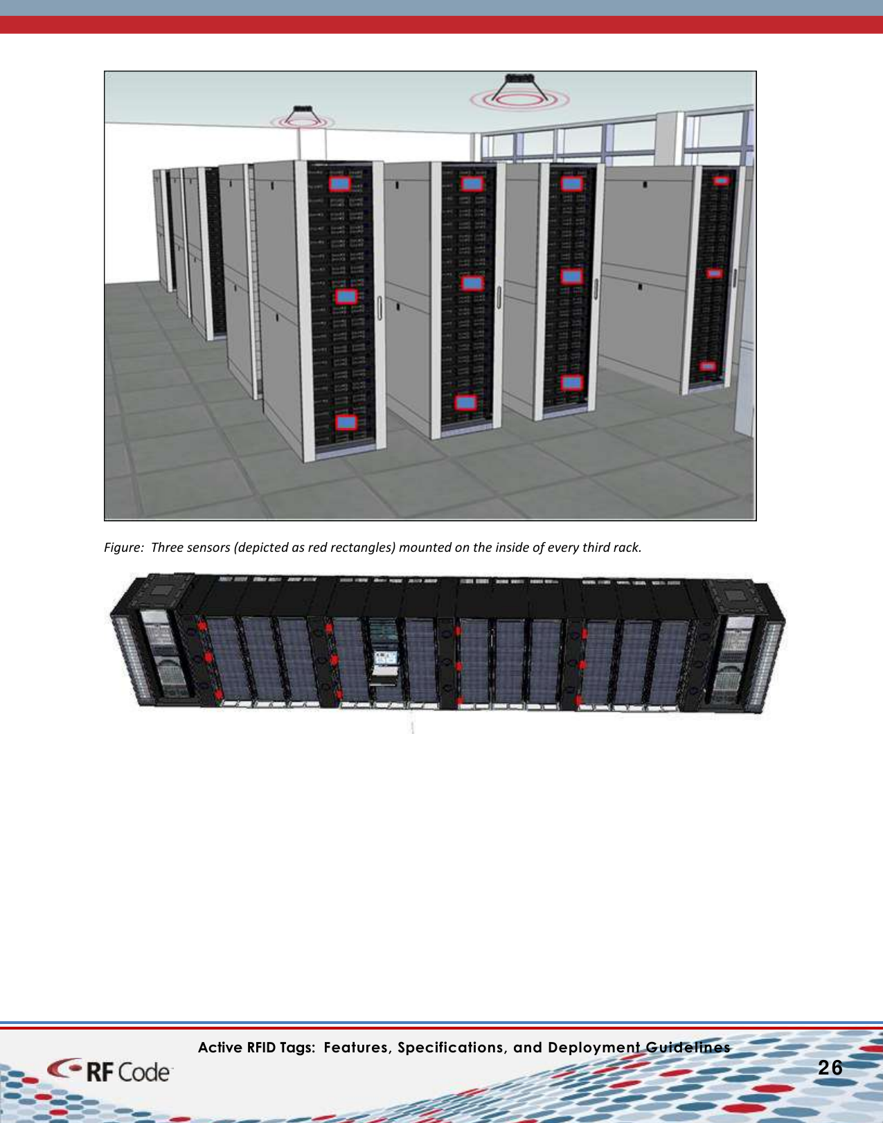
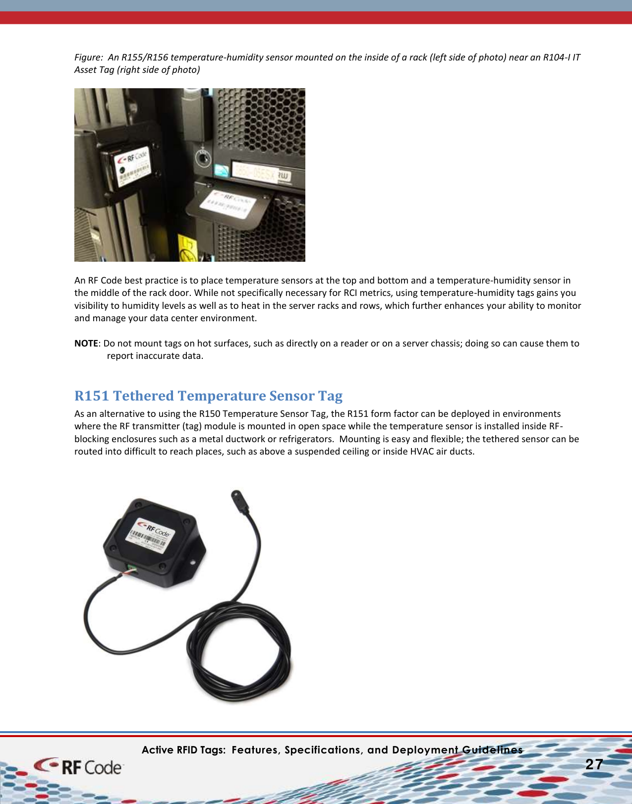
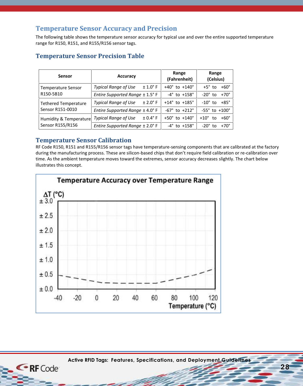
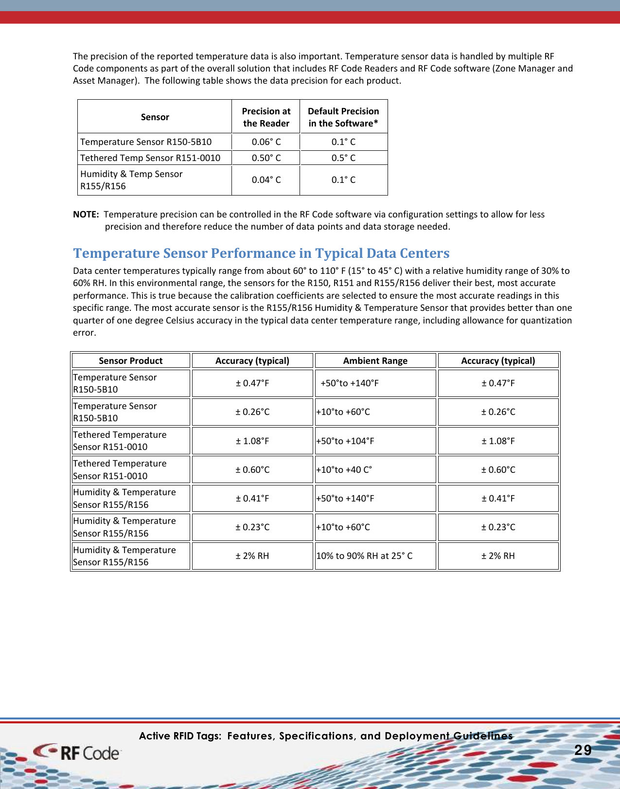
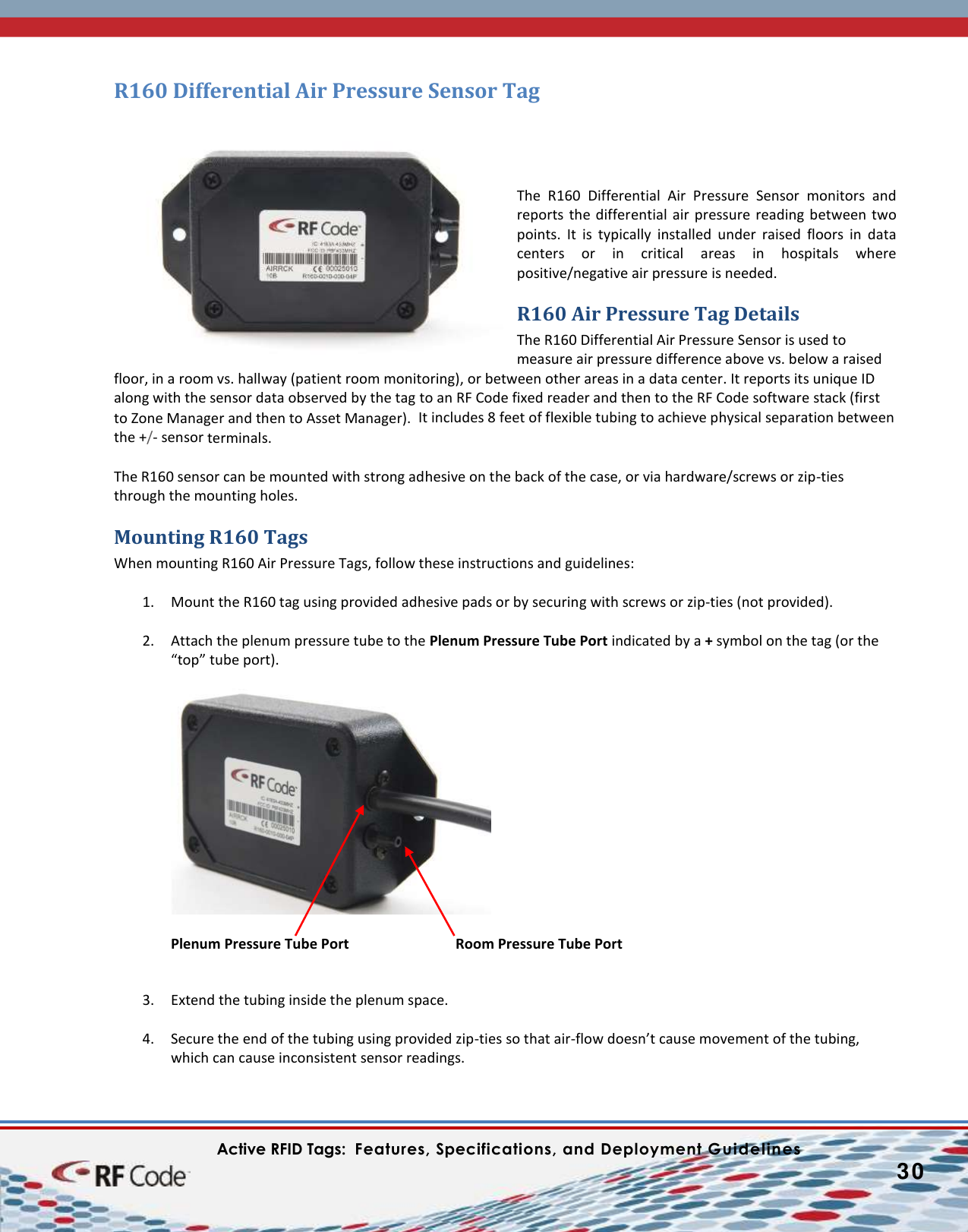
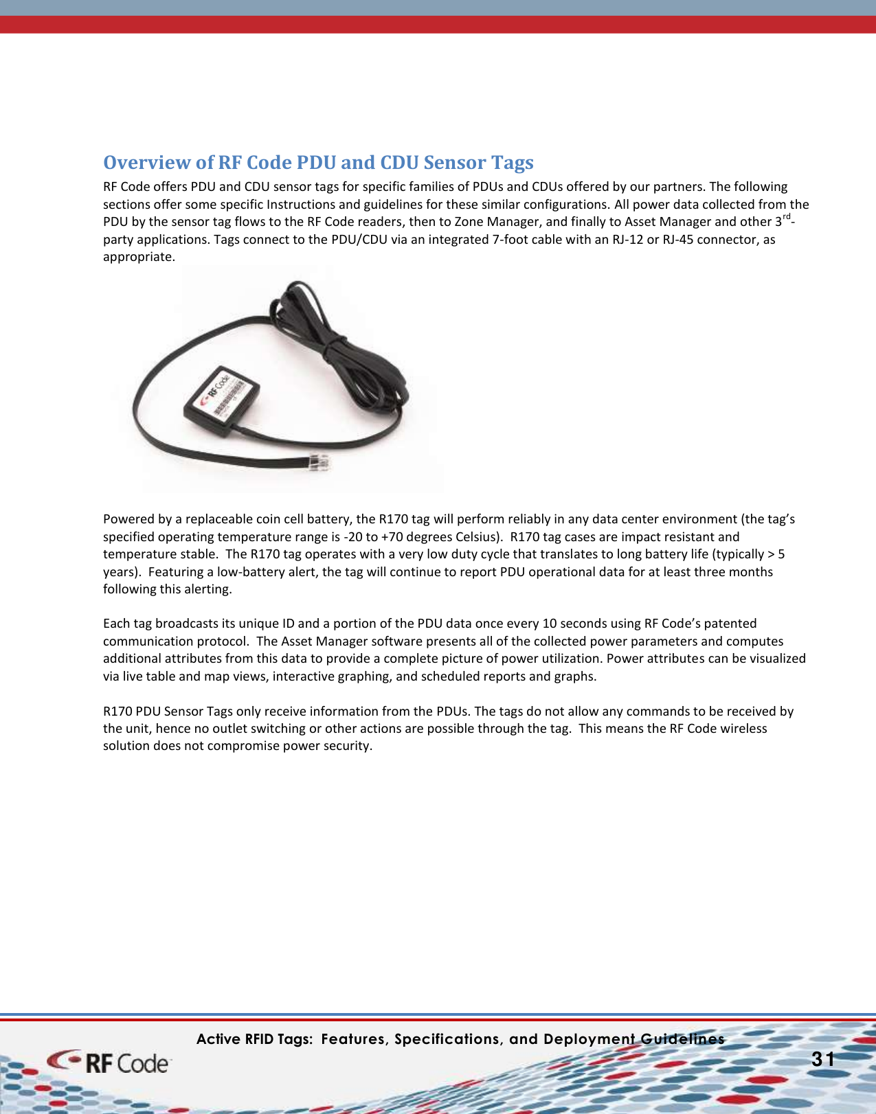
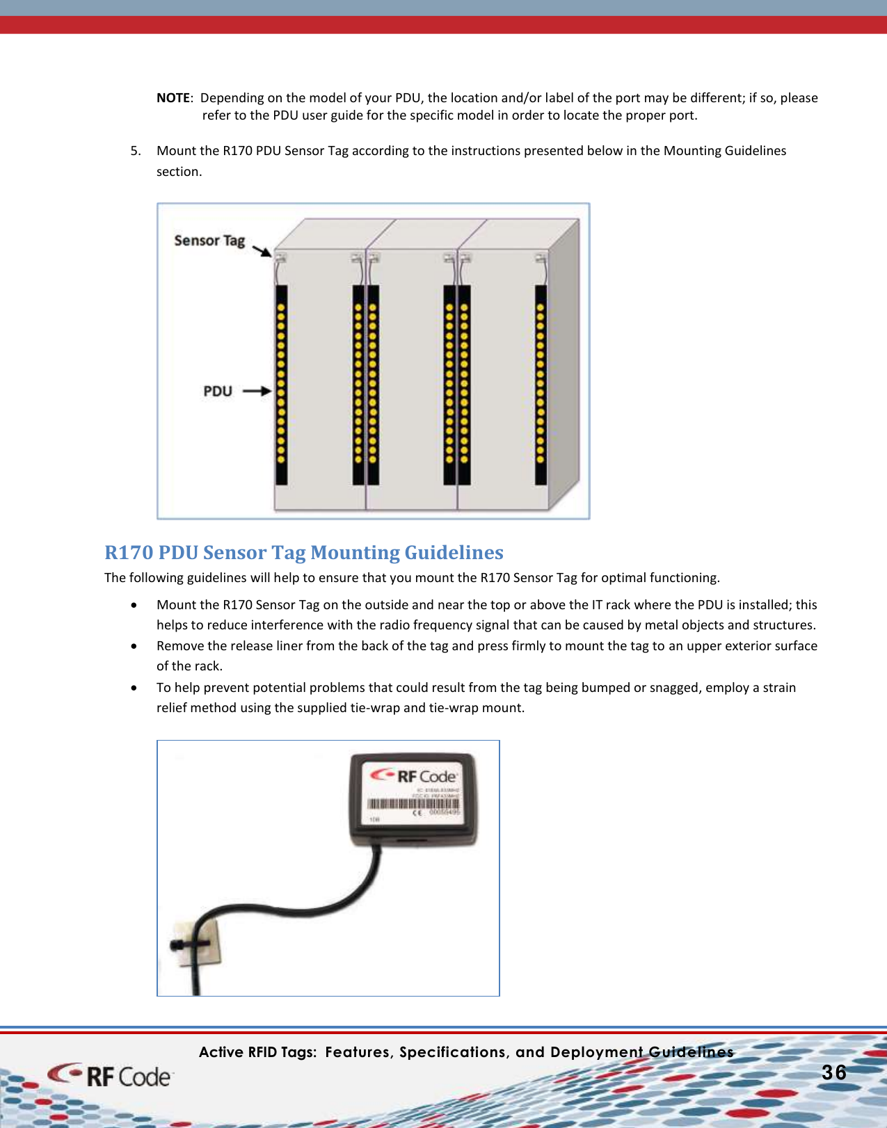
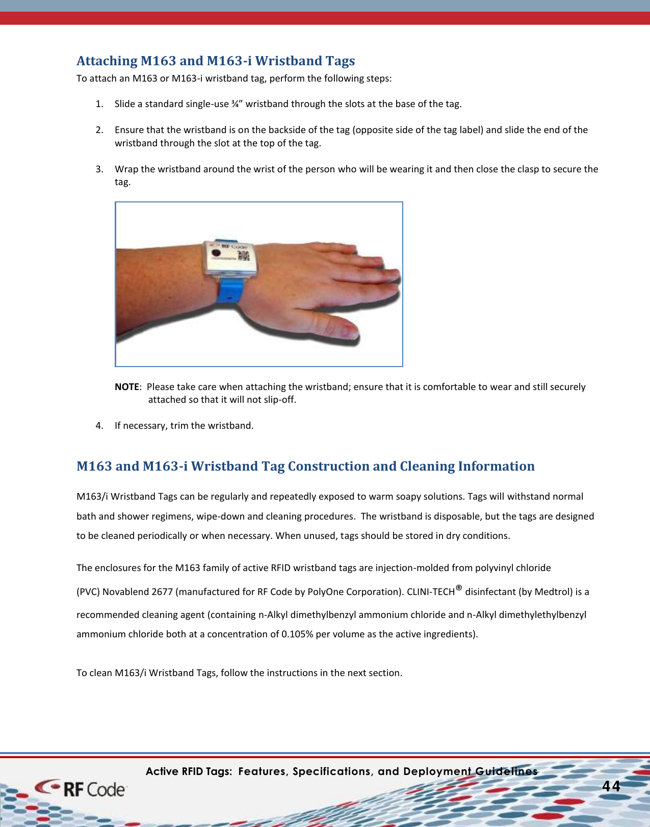
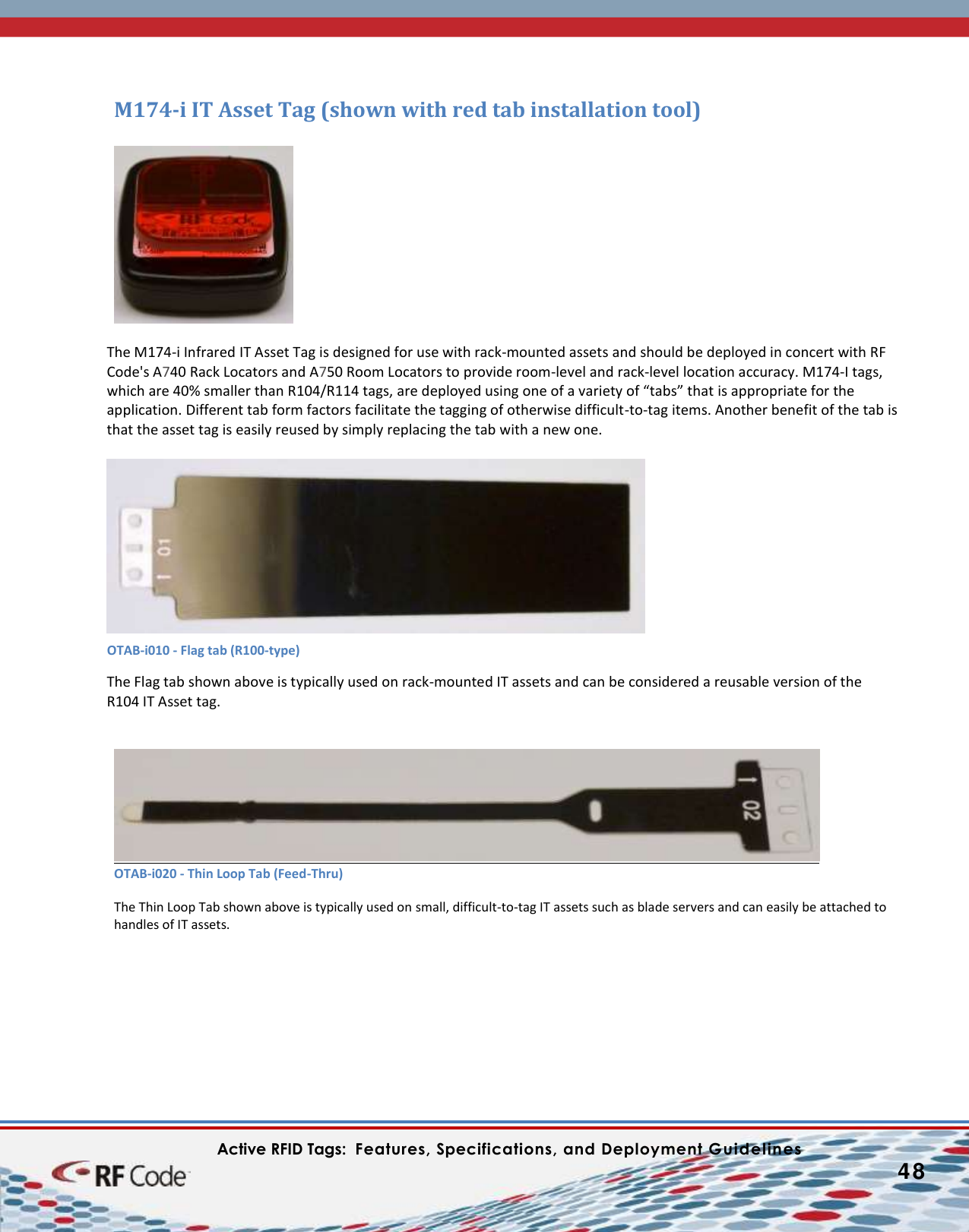
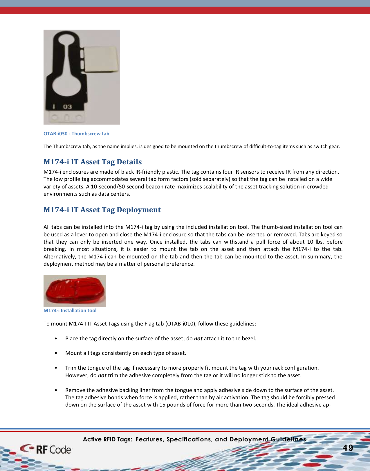
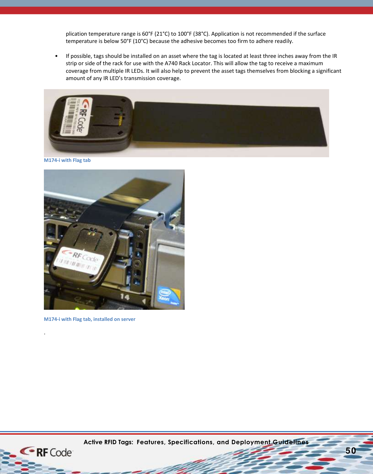
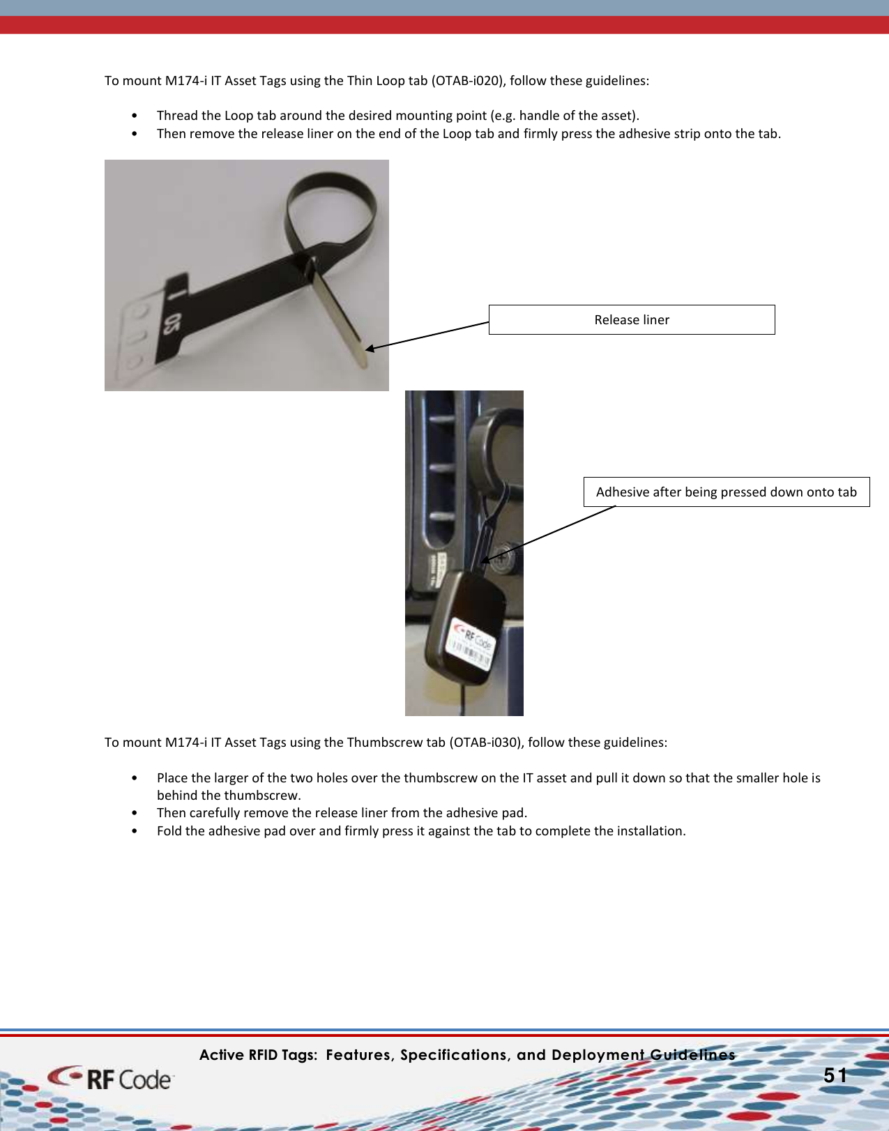
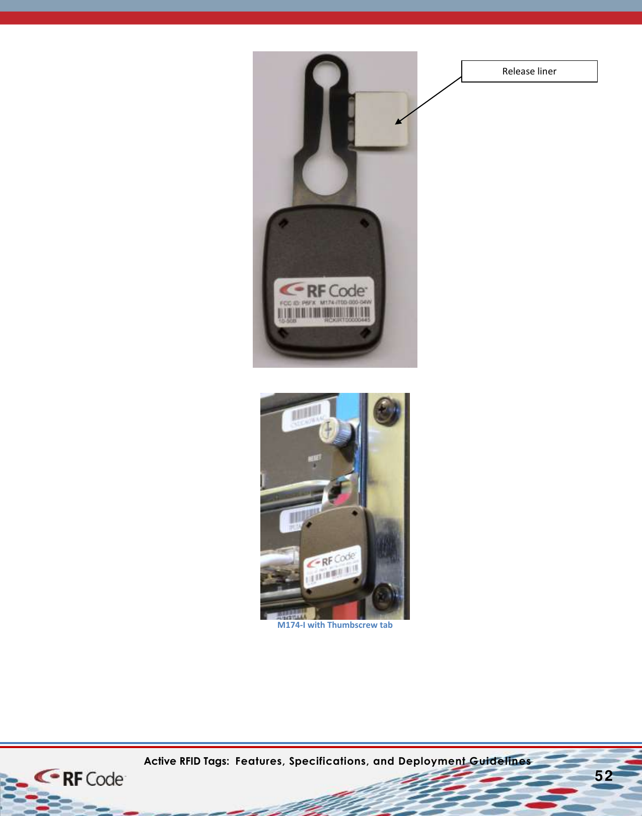
![Active RFID Tags: Features, Specifications, and Deployment Guidelines 47 M172 and M172-i Durable Tag Deployment The M172 and M172-i Durable Tags are particularly well-suited for hospital asset tracking. The tags can be deployed on expensive medical equipment so that these valuable assets can be located quickly for use in life-saving and other situations. M172-i Durable Tag deployed on a “patient vitals” machine. M172-I Durable Tags deployed on a wheelchair and underneath a patient bed. Cleaning M172 Durable Asset Tags The M172 Durable Asset Tag enclosure is injection molded from polycarbonate (PC) thermoplastic polymers. Polycarbonate is a very durable material, with high impact-resistance and can undergo large plastic deformations without cracking or breaking. This polymer is highly transparent to visible light and has better light transmission characteristics better than many kinds of glass. Tag Enclosure Sealing The tag enclosure is sealed using an ultrasonic welding process. If the tag is subjected to sustained loads under harsh or hostile environmental conditions, the enclosure may show signs of environmental stress cracking. The propagation of cracks over time can result in cosmetic and functional defects (e.g., broken seal, water penetration, electronic failure). Any product containing plastic material is susceptible to time-dependent viscoelastic cracking. Exposure to certain chemicals [including ammonia, highly concentrated alcohol solutions (e.g., 100% isopropyl alcohol) and oil-based products (e.g., mineral oil, vegetable oil)] can accelerate the stress cracking process. Customers are encouraged to evaluate product performance and fitness for use in their operating environment before deploying large populations of tags. RF Code, Inc. warrants all tags to be free from defects in materials and workmanship for a period of one (1) year.](https://usermanual.wiki/RF-Code/Z/User-Guide-2590945-Page-47.png)