RF Concepts PA-77DF Alpha 9500 linear amplifier User Manual Manual
RF Concepts LLC Alpha 9500 linear amplifier Manual
Manual

RF Concepts
Alpha 9500 Linear Amplifier
User Manual
www.rfconcepts.com
Product Release 1
Document Issue 1.1
February 2010

Alpha 9500 Linear Amplifier User Manual RF Concepts
Product Release 1
DOCNUMBER 9500
Document Issue 1.1
Page ii February 2010
Alpha 9500 Linear Amplifier User Manual
Prepared for RF Concepts by MRH/JH/LJW.
To reach technical support or obtain copies of this document, go to
www.rfconcepts.com.
Copyright © 2010 RF Concepts, LLC. All rights reserved. Specifications
subject to change without notice.

RF Concepts, LLC
Product Release 1 Contents
DOCNUMBER 9500
Document Issue 1.1
February 2010 Page iii
Contents
1. Introduction . . . . . . . . . . . . . . . . . . . . . . . . . . . . . . . . . . . . 1-1
1.1 Product Description 1-1
1.2 Product Capabilities 1-2
1.3 Safety Considerations 1-2
1.4 Related Products 1-3
1.5 Assistance 1-3
2. Amplifier Components and Specifications . . . . . . . . . . . . . . . . . . . 2-1
2.1 Cathode (Input-Match) Board 2-2
2.2 Center-Partition Board 2-3
2.3 Controls and Display 2-3
2.4 Display Board 2-4
2.5 Firmware 2-5
2.6 Master-Control Board 2-5
2.7 Output-Tank Circuit 2-5
2.8 Power Connections 2-5
2.9 Power Supply 2-6
2.10 Tube and Tube Deck 2-8
2.11 Specifications 2-8
3. Preparing Your Station . . . . . . . . . . . . . . . . . . . . . . . . . . . . . . 3-1
3.1 Prepare Your Station 3-1
3.2 Limitations of Operation at 90–130 VAC 3-3
4. Setting Up the Amplifier . . . . . . . . . . . . . . . . . . . . . . . . . . . . . 4-1
4.1 Unpack the Amplifier and Transformer 4-1
4.2 Install the Transformer 4-3
4.3 Connect the Transformer 4-4
4.4 Connect the Cables 4-7
4.5 Set the Input Drive 4-10
4.6 Connect the Transceiver Keying Line 4-10
5. Operating the Amplifier . . . . . . . . . . . . . . . . . . . . . . . . . . . . . . 5-1
5.1 Principles of Operation 5-1
Basic operation 5-1
Operational states 5-2
Tuning modes 5-4
Faults 5-5
5.2 Start Up the Amplifier 5-5
5.3 Tune the Amplifier 5-7
(Optional) Changing antenna settings 5-7
Autotuning 5-8
Manual tuning 5-9

Alpha 9500 Linear Amplifier User Manual RF Concepts, LLC
Contents Product Release 1
DOCNUMBER 9500
Document Issue 1.1
Page iv February 2010
5.4 Program the Amplifier Memory 5-10
5.5 Operate the Amplifier 5-12
6. Operating the Amplifier from a PC . . . . . . . . . . . . . . . . . . . . . . . . 6-1
6.1 Set Up to Operate from a PC 6-1
6.2 Operate from the PC 6-2
Main window 6-3
Simulated front panel 6-4
Tools menu 6-4
Options menu 6-5
7. Maintaining and Upgrading the Amplifier . . . . . . . . . . . . . . . . . . . . 7-1
7.1 Clean the Chassis 7-1
7.2 Retune the Amplifier 7-2
7.3 Replace the Tube and Fuses 7-2
7.4 Upgrade Firmware 7-3
On the Primary Board 7-4
On the Secondary Boards 7-5
8. Diagnosing Faults . . . . . . . . . . . . . . . . . . . . . . . . . . . . . . . . . 8-1
8.1 Overview 8-1
8.2 Fault Codes and Resolutions 8-2
Fault code 1 8-2
Fault code 2 8-4
Fault code 3 8-5
Fault code 4 8-5
Fault code 5 8-6
Fault code 6 8-6
Fault code 7 8-6
Fault code 8 8-6
Fault code 9 8-7
Fault code 10 8-7
Fault code 11 8-8
Fault code 12 8-9
Fault code 13 8-9
Fault code 14 8-9
Fault code 15 8-10
Fault code 16 8-10
Fault code 17 8-10
Fault code 18 8-10
Fault code 19 8-11
Terminology Term-1
Schematics Schem-1

RF Concepts, LLC
Product Release 1 List of Procedures
DOCNUMBER 9500
Document Issue 1.1
February 2010 Page v
List of Procedures
Procedure 3-1, “Prepare your station,” page 3–1
Procedure 4-1, “Unpack the amplifier and transformer,” page 4–1
Procedure 4-2, “Install the transformer,” page 4–3
Procedure 4-3, “Connect the transformer,” page 4–4
Procedure 4-4, “Connect the cables,” page 4–7
Procedure 4-5, “Connect the transceiver keying line,” page 4–10
Procedure 5-1, “Start up the amplifier,” page 5–5
Procedure 5-2, “(Optional) Change the antenna settings,” page 5–7
Procedure 5-3, “Autotune the amplifier,” page 5–8
Procedure 5-4, “Manually tune the amplifier,” page 5–9
Procedure 5-5, “Program the amplifier memory,” page 5–11
Procedure 5-6, “Operate the amplifier,” page 5–12
Procedure 6-1, “Set up to operate from a PC,” page 6–1
Procedure 7-1, “Clean the amplifier,” page 7–1
Procedure 7-2, “Replace the tube and fuses,” page 7–3
Procedure 7-3, “Upgrade firmware on the primary board,” page 7–4
Procedure 7-4, “Upgrade firmware on the secondary boards,” page 7–7

Alpha 9500 Linear Amplifier User Manual RF Concepts, LLC
List of Procedures Product Release 1
DOCNUMBER 9500
Document Issue 1.1
Page vi February 2010
RF Concepts, LLC
Product Release 1 1
DOCNUMBER 9500
Document Issue 1.1
February 2010 Page 1–1
1 Introduction
1.1 Product Description 1–1
1.2 Product Capabilities 1–2
1.3 Safety Considerations 1–2
1.4 Related Products 1–3
1.5 Assistance 1–3
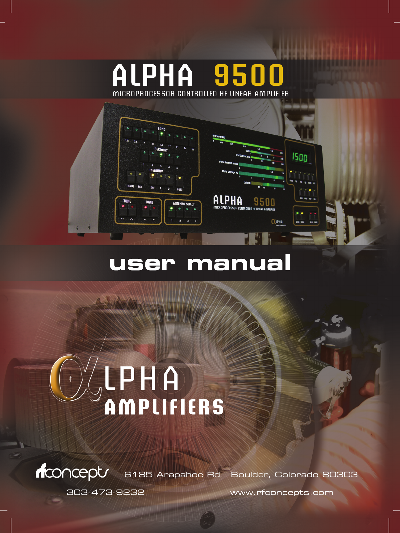
Congratulations on your purchase of a professional-quality Alpha 9500
linear amplifier.
1.1 Product Description
The Alpha 9500 (see Figure 1-1) is an self-contained autotune HF linear
power amplifier. It is capable of continuous operation at 1500 W peak
power output on single sideband (SSB), keyed continuous wave (CW),
slow-scan television (SSTV), radioteletype (RTTY), digital modes or
FM, with no time limit.
CAUTION
!
CAUTION! Study this manual carefully before operating your
amplifier for the first time. In particular, it is extremely important that
you thoroughly review the installation and operation sections. Failure
to do so could result in serious damage not covered under warranty.
Alpha 9500 Linear Amplifier User Manual RF Concepts, LLC
Introduction Product Release 1
DOCNUMBER 9500
Document Issue 1.1
Page 1–2 February 2010
11
1Figure 1-1 Alpha 9500
1.2 Product Capabilities
Product capabilities include:
•Continuous RF output. The Alpha 9500 is capable of 1.5 kW
continuous RF output on all commonly used modes and on any
authorized amateur frequency from 1.8 to 29.7 MHz (other than the
60-meter band).
•Compatibility with popular amateur transceivers and exciters. The
Alpha 9500 requires approximately 50-65 W peak RF drive for 1.5-
kW output.
•Capable of full CW break-in, QSK, and all digital modes when used
with any appropriate transceiver.
•Built-in protective functions. The control system incorporates
protective functions that minimize the probability of accidental
damage to the amplifier or its power tubes. In most cases, when one
of the protective functions is tripped, the amplifier goes to standby.
•USB and serial interface allow for remote operations, diagnostics,
and firmware upgrades.
1.3 Safety Considerations
•Locate the Alpha 9500 where there is good air circulation all around
and on top of the cabinet. The unit may become hot during operation.

11
1
DOCNUMBER 9500
Document Issue 1.1
February 2010 Page 1–3
RF Concepts, LLC Alpha 9500 Linear Amplifier User Manual
Product Release 1 Introduction
•Use proper lifting techniques and two people when moving the Alpha
9500. The Alpha 9500 weighs approximately 69 pounds when the
transformer is installed.
•Although the Alpha 9500 meets international safety standards and
FCC regulations, remember that the equipment works with high
voltages that can be LETHAL!
This operating manual holds information, cautions, and warnings that you
must follow to ensure safe installation and operation. Read Chapter 1
before attempting to unpack or operate the Alpha 9500. Failure to perform
procedures properly may result in amplifier damage, fire hazard, or
electric shock.
!
IMPORTANT •Never open the amplifier case without unplugging the unit
from the wall outlet.
•Never stick objects into holes in the case.
•Never touch an antenna during transmission.
•Never attempt to turn on the amplifier without the cover
securely in place (all attachment screws reinserted).
•Never turn the amplifier back on after a hard fault without
waiting at least 20 seconds.
•Never press the ON (AMP) button after the amplifier faults to
power off.
•Never allow liquids to enter the amplifier through the cover
holes.
•Never cover or obscure the exhaust holes in the cover of the
amp.
1.4 Related Products
Other products available to enhance your use of the Alpha 9500 include:
•Alpha 2100 full-1500 W-rated 50-ohm dummy loads
•Alpha 4500 series SWR meters and wattmeters
For more information, go to www.rfconcepts.com or call 303-473-9232.
1.5 Assistance
Technical assistance from RF Concepts is available from several sources.

Alpha 9500 Linear Amplifier User Manual RF Concepts, LLC
Introduction Product Release 1
DOCNUMBER 9500
Document Issue 1.1
Page 1–4 February 2010
11
1•Go to our website at www.rfconcepts.com and click Support. On
this site you can get the following assistance:
•FAQs
•Legacy equipment information
•Manuals
•Repair information
•Software downloads
•Tech tips
•Technical support
•E-mail us at service@rfconcepts.com.
•Fax us at 303-473-9660.
•Phone us at 303-473-9232.

RF Concepts, LLC
Product Release 1 2
DOCNUMBER 9500
Document Issue 1.1
February 2010 Page 2–1
2 Amplifier Components and Specifications
2.1 Cathode (Input-Match) Board 2–2
2.2 Center-Partition Board 2–3
2.3 Controls and Display 2–3
2.4 Display Board 2–4
2.5 Firmware 2–5
2.6 Master-Control Board 2–5
2.7 Output-Tank Circuit 2–5
2.8 Power Connections 2–5
2.9 Power Supply 2–6
2.10 Tube and Tube Deck 2–8
2.11 Specifications 2–8
The Alpha 9500 uses a single 3CX1500 (8877) high-mu external-anode
triode ceramic tube for amplification. The main power supply is an
unregulated transformer/rectifier/capacitor power supply for the high-
voltage (HV) and heater circuits. All other power supplies are regulated.
The biasing and tank circuits are similar in most respects to those of the
Alpha 9500’s predecessor, the Alpha 77. The unit has thoroughly modern
computer-controlled power supply and control circuitry. Extensive safety
measures protect the amplifier against most off-nominal conditions. It has
USB and RS-232 interfaces to aid in remote operation. All front-panel
features are accessible via these interfaces.
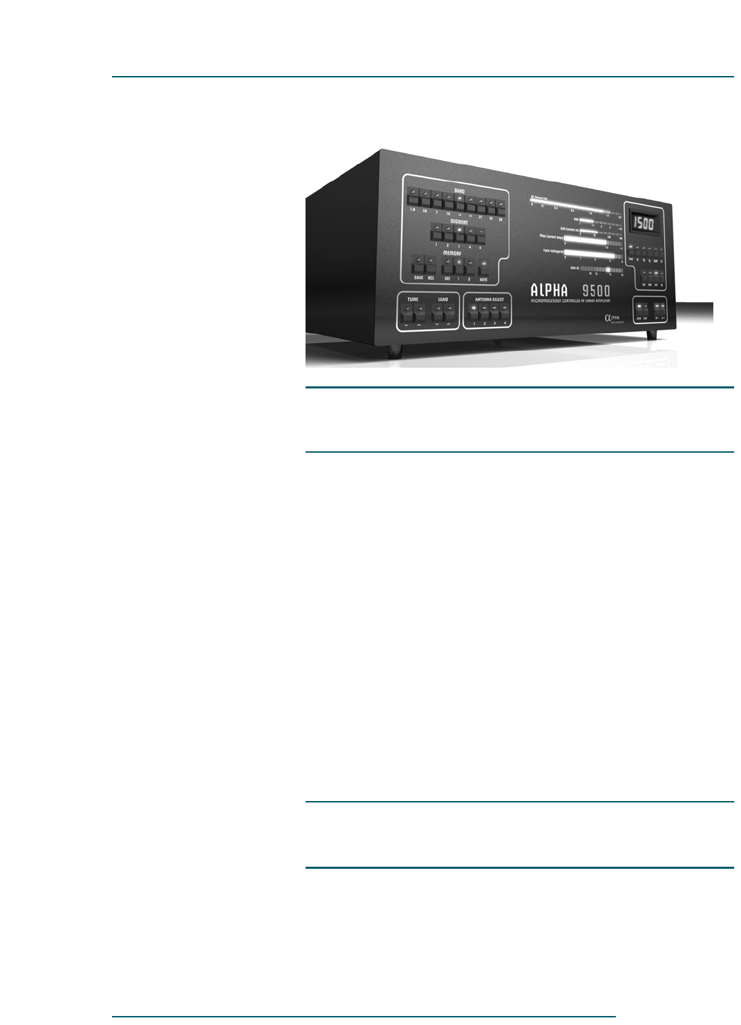
There are six main circuit boards in the amplifier. Communications
among these is via an I2C bus.
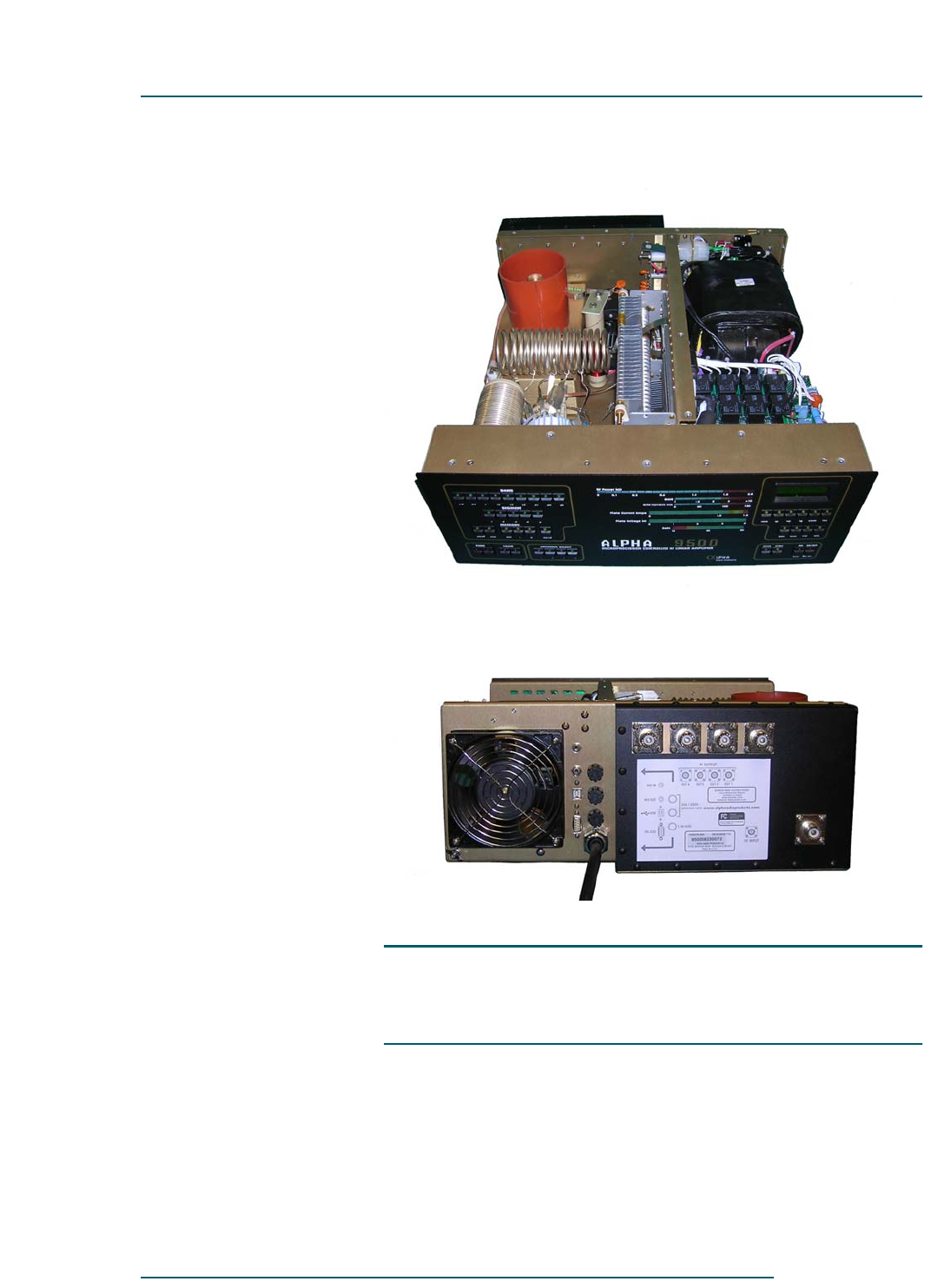
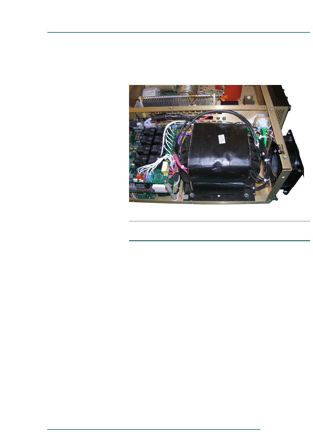
The amplifier front and back are shown below (see Figure 2-1 and
Figure 2-2). Amplifier components are listed alphabetically and described
below.
Alpha 9500 Linear Amplifier User Manual RF Concepts, LLC
Amplifier Components and Specifications Product Release 1
DOCNUMBER 9500
Document Issue 1.1
Page 2–2 February 2010
22
2
Figure 2-1 Amplifier front and interior
Figure 2-2 Amplifier back
2.1 Cathode (Input-Match) Board
The cathode board, housed in the tube deck, consists of a set of Pi filters
controlled by a set of five relays that are enabled based on the band-switch
setting.
22
2
DOCNUMBER 9500
Document Issue 1.1
February 2010 Page 2–3
RF Concepts, LLC Alpha 9500 Linear Amplifier User Manual
Product Release 1 Amplifier Components and Specifications
2.2 Center-Partition Board
The center-partition board contains the RF decoupling circuit on the B+
line as well as the crowbar safety circuit. When you remove the top cover
of the Alpha 9500, the spring metal of this safety device shorts out the B+
line.
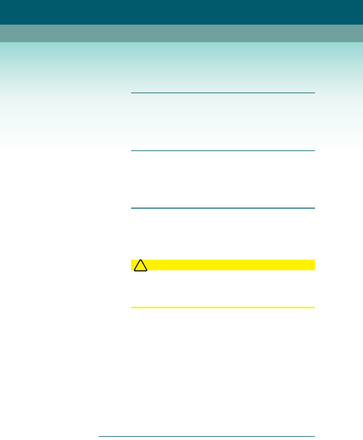
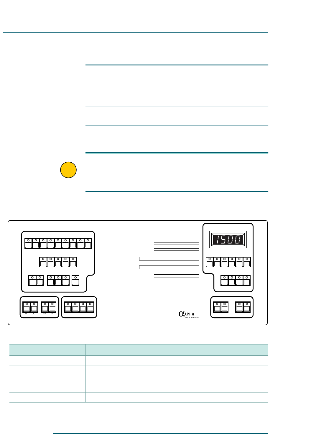
2.3 Controls and Display
The Alpha 9500 controls enable you to adjust and monitor the amplifier
as needed (see Figure 2-3).
!
IMPORTANT Note that the front panel has, in the upper-right corner, a 7-segment
LED display. The display contains 4 digits.
The buttons below the display control what kind of value is displayed:
FLT, Fwd, Ig, Ip, SWR, or Vp.
Figure 2-3 Amplifier controls
BAND
MEMORY
SAVE RCL DEF 1 2 AUTO
TUNE LOAD ANTENNA SELECT
1.8 3.5 7 10 14 18 21 24 28
12345
1234
RF Power kW
SWR
Grid Current mA
Plate Current Amps
Plate Voltage kV
Gain
0 0.1 0.3 0.6 1.0 1.5 2.5
1 1.5 2 3 >10
0 50 100 150
0 1.0 1.5
02314
10 30 50
MICROPROCESSOR CONTROLLED HF LINEAR AMPLIFIER
ALPHA
Fwd IpVpIg SWR FLT
DIM SND PEP DEL
OPER STBY ON/OFFON
ANT SELAMP
SEGMENT
9500
Table 2-1 Amplifier Buttons (listed alphabetically)
Button Purpose
ANTENNA SELECT Determines which one or two of the four antenna output ports to use.
BAND Selects an amateur band, designated in megahertz (MHz).
DEL Displays the delivered power from the amplifier to the selected antenna
port in watts (W).
DIM Controls the brightness of the display LEDs.

Alpha 9500 Linear Amplifier User Manual RF Concepts, LLC
Amplifier Components and Specifications Product Release 1
DOCNUMBER 9500
Document Issue 1.1
Page 2–4 February 2010
22
2
2.4 Display Board
The display board is the largest board in the amplifier and spans the entire
inside front panel. It has three microcontrollers, one each to control the
stepper motors; the LEDs and 7-segment display and push buttons; and
the sound controller.
FLT Sets the 7-segment display to show the last fault. Also loads new
firmware.
Fwd Sets the 7-segment display to show forward power in W.
GAIN Displays the gain in decibels (dB).
GRID CURRENT Displays the grid current in milliamperes (mA).
Ig Sets the 7-segment display to show grid current in mA.
Ip Sets the 7-segment display to show plate current in mA.
LOAD Controls the load capacitor.
MEMORY Selects one of three sets of segment memories:
•DEF — factory-default settings
•1, 2 — User 1 and User 2 memories
•AUTO — autotune
ON (AMP) Turns the amplifier tube and voltage on.
ON/OFF (ANT SEL) Turns antenna select on; the amplifier tube is not on.
OPER Sets the amplifier to the operate position.
PEP Toggles between peak power (PEP) and average power.
PLATE CURRENT meter Displays the plate current in milliamperes (mA).
PLATE VOLTAGE meter Displays the plate voltage in volts (V).
RCL (Currently nonfunctional)
RF POWER kW meter Displays the forward power in W.
SAVE Saves the current settings.
SEGMENT Selects different frequencies within each band.
SND Controls the sound volume (not yet implemented).
STBY Sets the amplifier to standby (bypass).
SWR meter Sets the 7-segment display to show SWR.
TUNE (UP or DOWN) Controls the tune capacitor.
Vp Sets the 7-segment display to show plate voltage in V.
Table 2-1 Amplifier Buttons (listed alphabetically) (Continued)
Button Purpose

22
2
DOCNUMBER 9500
Document Issue 1.1
February 2010 Page 2–5
RF Concepts, LLC Alpha 9500 Linear Amplifier User Manual
Product Release 1 Amplifier Components and Specifications
2.5 Firmware
The Alpha 9500 firmware controls and implements most amplifier
features and functions.
You can upgrade the master firmware via a serial or USB connection to a
Microsoft Windows PC. For information, see Chapter 7, “Maintaining
and Upgrading the Amplifier.”
2.6 Master-Control Board
The master-control board monitors all critical voltages and currents in the
amplifier, as well as the input power and output forward and reflected
power. It uses these converted values to control the amplifier’s operation
and to send data to the front panel, so that the correct LEDs are lit and the
stepper motors move to the correct positions. A standard 9-pin RS-232
serial port is provided for control and monitoring and is found on the back
of the Alpha 9500. A USB port is also provided. Either port may be used,
but only one may be active at any one time.
The amplifier automatically senses when a PC is attached to the USB port,
and uses that port. If nothing is connected to the USB, the amplifier
automatically switches back to the RS-232 serial port.
2.7 Output-Tank Circuit
The output-tank circuit provides reliable high-efficiency, low-distortion
performance in a very compact volume. The basic topology is “pi-L”,
which provides harmonic attenuation adequate to meet the requirements
of all countries globally that permit power outputs of 1500 W.
Band switching is under automatic control, accomplished by a 4-wafer
band switch. These wafers are used as multifunction tap selectors, which
simultaneously select band taps on the inductors and include varying
amounts of capacitance to provide band spread on the tune and load
capacitors. The wafers are in the RF tank area. The band-switch position
is controlled by a stepper motor in the front subchassis.
2.8 Power Connections
When the Alpha 9500 is powered up, it measures the line voltage and
chooses, then sets the appropriate tap setting for the transformer primary.
After it is powered up, it does not reset the tap. The amplifier can be set
Alpha 9500 Linear Amplifier User Manual RF Concepts, LLC
Amplifier Components and Specifications Product Release 1
DOCNUMBER 9500
Document Issue 1.1
Page 2–6 February 2010
22
2
to override autotaps election and use any primary tap; it may be useful to
do so if your line voltage is unsteady or on the edge of a tap setting. For
more information, contact RF Concepts technical support.
Figure 2-4 Primary connections
2.9 Power Supply
The power supply has two major sections: a switch-mode supply for the
logic circuitry and a conventional transformer supply for all other
voltages.
When the amplifier is plugged into the AC line, the switch-mode supply
is always on and all the microprocessors are active. It is usual for some of
the front panel LEDs to blink momentarily when the unit is first plugged
in.
The remaining voltages are produced by the mains and HV boards,
described below.
22
2
DOCNUMBER 9500
Document Issue 1.1
February 2010 Page 2–7
RF Concepts, LLC Alpha 9500 Linear Amplifier User Manual
Product Release 1 Amplifier Components and Specifications
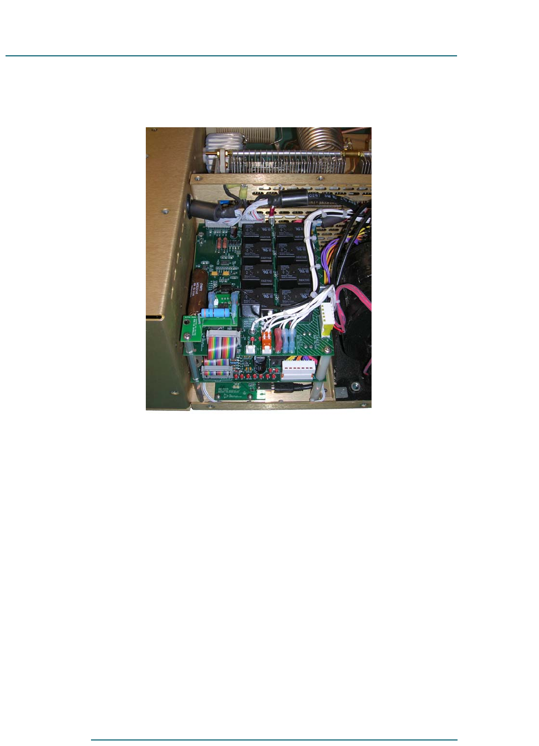
Mains Board
Figure 2-5 Mains board
Power-supply functions are split between the mains board and the HV
board. The mains board deals mostly with the primary side of the
transformer. The various taps for the transformer primary are routed
through this board and so is the AC line input. Relays on the mains board
connect the AC line to the appropriate taps on the transformer primary.
When the ON (AMP) button is pressed, the microprocessor on the mains
board samples the line voltage and determines which tap to select. That
voltage tap remains selected until the amplifier is turned off, and does not
change even if the line voltage fluctuates.
If you install your amplifier in a location where the line voltage is not
steady, you can force the tap selection via the serial or USB port. For
information on how to force tap selection, contact RF Concepts technical
support.
Also on the mains board is a step-start circuit. This circuit consists of a
relay and a resistor, which are time-sequenced to limit the inrush current
into the amplifier when it is first turned on.

Alpha 9500 Linear Amplifier User Manual RF Concepts, LLC
Amplifier Components and Specifications Product Release 1
DOCNUMBER 9500
Document Issue 1.1
Page 2–8 February 2010
22
2
HV Board
The main high voltage for the amplifier is created on the HV board using
a full-wave bridge rectifier and a bank of capacitors. This power supply
has two 10-ohm resistors, one in the positive (B+) lead and one in the
negative return to the tube cathode. This combination of resistors limits
the surge current in the case of a B+ arc.
When the power-supply current exceeds about 2.5 amps, a latching relay
opens the coil circuit of the mains tap relays on the mains board, causing
the amplifier to go to the power-off state. This hard-fault circuit operates
independently of microprocessor control.
All power-supply filter capacitors on this board have bleeder resistors that
discharge the capacitors in less than 60 seconds. If you must work on this
board, confirm the discharged condition with a voltmeter, due to the
remote possibility of bleeder resistor failure.
2.10 Tube and Tube Deck
The Alpha 9500 uses a single 8877 triode tube. The tube operates well
within its published ratings. It is operated in Class AB1, with a plate
voltage of 3300 V (nominal, full output, key down) and a cathode voltage
of 9.4 V.
The tube deck is a mechanical assembly that houses the tube socket and
the cathode (or input match) printed circuit board (PCB).
A temperature sensor mounted on the cathode PCB measures the
temperature of the air immediately below the tube socket. This
temperature measurement is used by the master controller as part of the
fault-detection software.
2.11 Specifications
The Alpha 9500 linear amplifier specifications are as follows.
Table 2-2 Alpha 9500 linear amplifier specifications
Parameter Value
Frequency coverage All amateur frequencies in the range 1.8–29.7 MHz
Power output 1500 Watts minimum
3rd Order IM <–30 dBc
SWR tolerance 3:1
Drive power 65 Watts nominal
Tube 3CX1500/8877

22
2
DOCNUMBER 9500
Document Issue 1.1
February 2010 Page 2–9
RF Concepts, LLC Alpha 9500 Linear Amplifier User Manual
Product Release 1 Amplifier Components and Specifications
Cooling Forced air
Antenna outputs 4xSO-239 connectors
Antenna selection 1 or 2 outputs per band/segment
Input SO-239 connector
Tuning/Band switching Automatic; manual override possible
Power 100, 120, 200, 220, 240V AC, 50/60 Hz
Power tap selection Automatic
Interface Serial port with full remote-control capability
Protection Protected against all common faults
Display Bar graphs as well as digital panel meter
T/R switching Vacuum relays; QSK (full break-in)
Bypass capability 1500 Watts
Wattmeter and antenna selector active in ON1 to allow use with exciter.
HV and tube come on in ON2 for linear use.
Width 17.5 inches
Height 7.5 inches
Depth 19.75 inches
Weight 76 pounds
Table 2-2 Alpha 9500 linear amplifier specifications (Continued)
Parameter Value

Alpha 9500 Linear Amplifier User Manual RF Concepts, LLC
Amplifier Components and Specifications Product Release 1
DOCNUMBER 9500
Document Issue 1.1
Page 2–10 February 2010
22
2

RF Concepts, LLC
Product Release 1 3
DOCNUMBER 9500
Document Issue 1.1
February 2010 Page 3–1
3 Preparing Your Station
3.1 Prepare Your Station 3–1
3.2 Limitations of Operation at 90–130 VAC 3–3
3.1 Prepare Your Station
The Alpha 9500 is capable of dramatically improving the performance of
your amateur station. It is important that you observe good engineering
practices to achieve all the benefits of such a station in a safe and reliable
manner.
This chapter provides a few important operational considerations. We
recommend that you also consult a good source of general information
such as the latest Amateur Radio Relay League (ARRL) Handbook for
Radio Amateurs, especially if this is the first high-power amplifier that
you have used.
Procedure 3-1 Prepare your station
Step 1 Provide 220 VAC power.
The amplifier runs best when powered by a 200–240 VAC circuit. If you
do not have a 220 VAC outlet in your station, have a licensed electrical
contractor install one. A minimum of a 20 A capacity is required. A 20-A
breaker on your 220-V circuit is sufficient.
When you size the circuit, be sure to include the current drawn by other
equipment that may be on the same circuit.
Select a location for the outlet as close as possible to where you expect to
operate the amplifier. If you are not sure or contemplate moving the
amplifier, consider installing two outlets.
There are many styles of power plugs, some of which are country-
specific. For this reason, the amplifier is not shipped with a plug. Ask your
contractor for two or three matching plugs during installation.
Ask the contractor to measure the voltage and record it for reference.

Alpha 9500 Linear Amplifier User Manual RF Concepts, LLC
Preparing Your Station Product Release 1
DOCNUMBER 9500
Document Issue 1.1
Page 3–2 February 2010
33
3
Although the amplifier can run when connected to a 110 VAC outlet, you
WILL NOT achieve full-legal-limit output in this case. Rather, you
should not expect more than 1000 W output. For more information on the
limitations of operation when connected to a 110 VAC outlet, see Section
3.2, “Limitations of Operation at 90–130 VAC,” page 3–3.
Note that, when the amplifier is plugged in and turned on, it is normal to
hear the capacitors and band-switch zero themselves and a slight “clunk”
as the transformer comes up to full load.
Step 2 Provide proper airflow.
It is critical that airflow around the amplifier remain unimpeded at all
times and that the top of the amplifier remain clear of any restrictions.
Maintain at least 3 inches of clearance around the amplifier to allow for
unobstructed airflow.
If you are mounting the amplifier in a console, ensure that the exhaust air
is properly and fully removed from the console. If outlet air is drawn back
into the amplifier air intake and recirculated, the amplifier gets hotter and
hotter, resulting in degraded performance or even failure. If you are
designing your own console, consider putting in additional fans and/or
ducting to deal with waste heat.
Minimize the possibility of dust or other contamination getting drawn into
or falling on the amplifier. Periodically (at least annually) clean the dust
out of the amplifier, paying particular attention to the tube fins. We
recommend the use of compressed air for dust removal.
Step 3 Ready your antenna for 1500 W.
Ensure that all antennas are rated for 1500 W and that they are carefully
tuned and installed for minimum voltage SWR.
Many antennas that are suitable for general use are unsuited for operation
with a full 1500 W of power. At this power level in a 50-ohm circuit, the
RMS current is 5.5 A and the peak RF voltage is 387 V. For SWR = 2:1,
these values double to 11 A and 775 V. The actual voltage and current at
various points in or on your antenna may actually be many times these
values.
Step 4 Provide adequate RF cabling.
The importance of a well-constructed feed-line system cannot be
overstated.
Use good-quality low-loss coaxial cable of size RG/8 or larger. The Alpha
9500 is intended for a nominal 50-ohm load. With proper matching (50
ohms) between amplifier and feedline, open-wire feeders or lines of other
than 50 ohms may be used.

33
3
DOCNUMBER 9500
Document Issue 1.1
February 2010 Page 3–3
RF Concepts, LLC Alpha 9500 Linear Amplifier User Manual
Product Release 1 Preparing Your Station
Use new, clean connectors and install them according to manufacturer
recommendations. Clean the connectors after soldering them and before
mating them with the amplifier.
Install system feedlines following good engineering practice and
according to manufacture recommendations.
NOTE: The FCC requires users to check their installations for
compliance with published values for allowable exposure to RF fields.
This information is available in ARRL publications, FCC printed rules,
and on the web. We strongly recommend that you do this for any
installation, both fixed and at an expedition or contest site.
If you have any questions regarding engineering your amplifier into
your amateur radio station, go to www.rfconcepts.com and click
Support.
Step 5 Provide surge protection.
Induced energy from nearby electrical storms or other power transients
may damage components. Such damage is not covered under warranty. It
is therefore important to use a good lightning arrestor. However the only
lightning-proof solution available is to disconnect antenna feedlines and
AC power when the equipment is not in use.
NOTE: Whenever the amplifier is online — either off, in standby
(STBY), or in warm-up with the WAIT LED lighted — the amplifier is
bypassed and the exciter is connected directly to the antenna. The
throughput limit in all cases is 1500 W.
3.2 Limitations of Operation at 90–130 VAC
Electrical-power equipment draws twice as much primary current from
120 V mains as from 240-V mains. Therefore, if you operate the Alpha
9500 on typical 120 V/20 A household circuit without exceeding the 20-
A circuit rating, you limit maximum peak power output to about
600–1000 W.

Alpha 9500 Linear Amplifier User Manual RF Concepts, LLC
Preparing Your Station Product Release 1
DOCNUMBER 9500
Document Issue 1.1
Page 3–4 February 2010
33
3
If your line voltage is below 110 V under load, do not expect to be able
to get 1500 W output (see Table 3-1).
Table 3-1 Amplifier behavior with nonstandard line voltages
Line voltage Expected behavior
Low: 90–110 V Power outputs above 1000 W are not expected.
Normal: 110–130 V 1500 W PEP operation (CW or SSB) may be
possible if your AC line service has sufficient
current capacity (30-A circuit recommended).
However, 1500 W continuous should not be
expected.
High: >250 V Lifetime of the tubes may be reduced. Ask your
utility company if they can reduce your line
voltage. If this is not possible, consider placing
your own step-down transformer in line between
the AC outlet and the amplifier. A transformer
with at least 4-kVA rating is required, due to the
nature of the current waveform in the primary.
Another choice for voltage control, a ferroresonant
voltage regulator, is an expensive solution, but is a
good way to stabilize primary voltage.
NOTE If you intend to operate the amplifier at ~120 V or if other equipment
draws current from the same circuit as the amplifier, the following
apply:
1. If you replace the factory-shipped 20 A/250 V fuses with 25 A/250
V “slo-blo” fuses (for line voltages of less than 100 V), be aware
that the higher current at the lower voltage significantly warms the
amplifier’s power cord. The cord (as well as fuse holders and
some internal connectors) are operating near their maximum
ratings due to the current demand at lower voltages.
2. Ensure that the AC cord is not coiled too tightly or placed where
normal air flow is restricted, causing it to overheat.
3. You must change the two lower 2A fuses on the rear panel to 5A
fuses to allow for the increased in-rush current.

RF Concepts, LLC
Product Release 1 4
DOCNUMBER 9500
Document Issue 1.1
February 2010 Page 4–1
4 Setting Up the Amplifier
4.1 Unpack the Amplifier and Transformer 4–1
4.2 Install the Transformer 4–3
4.3 Connect the Transformer 4–4
4.4 Connect the Cables 4–7
4.5 Set the Input Drive 4–10
4.6 Connect the Transceiver Keying Line 4–10
!
IMPORTANT The Alpha 9500 is easy to set up, tune, operate, and maintain.
However, failure to carry out each procedure exactly as described in
this manual is likely to lead to amplifier damage, which is not covered
under warranty. Damage to other station equipment may also result.
Proceed slowly throughout these procedures to avoid bumping and
damaging adjacent wires, connectors, and components.
4.1 Unpack the Amplifier and Transformer
Procedure 4-1 Unpack the amplifier and transformer
Step 1 Remove the amplifier and transformer from their cartons.
The Alpha 9500 ships in two heavy-duty cardboard cartons, each
mounted on a wooden pallet and strapped down for secure shipping. The
amplifier weighs 39 lb (18 kg); the transformer weighs 43 lb (20 kg).
1a Remove the strap securing the two boxes to the pallet.
1b Inspect the boxes for shipping damage.
1c Unpack the cartons.
1d Retain the pallet and cartons in case you need to ship the unit later.
Step 2 Inspect the amplifier and transformer for shipping damage.
If you find damage, call RF Concepts at 303-473-9232.
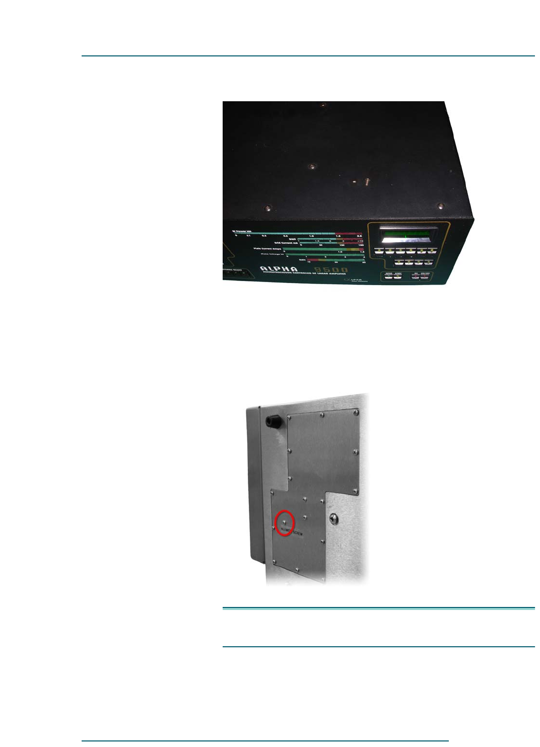
Step 3 Remove the blower screw from the bottom of the amplifier.
3a Place the amplifier on the bench or desk where it is to be used.
3b Remove the cover screws (Figure 4-1) and the cover.
Alpha 9500 Linear Amplifier User Manual RF Concepts, LLC
Setting Up the Amplifier Product Release 1
DOCNUMBER 9500
Document Issue 1.1
Page 4–2 February 2010
44
4
Figure 4-1 Cover screws
3c Rotate the amplifier onto its right hand side.
3d While looking at the bottom, locate and remove the screw (labeled
BLOWER SCREW, Figure 4-2) that holds the blower in place
during shipping.
Figure 4-2 Blower screw
NOTE: Before shipping, reinsert the screw to prevent damage to the
blower.
3e With the cover off, remove the Delrin rod holding the tube in place.
Retain the rod in case you need to ship the unit later.
44
4
DOCNUMBER 9500
Document Issue 1.1
February 2010 Page 4–3
RF Concepts, LLC Alpha 9500 Linear Amplifier User Manual
Product Release 1 Setting Up the Amplifier
4.2 Install the Transformer
NOTE •The transformer is very heavy. When moving it, use due caution
and handle only by the lifting handle.
•The extra piece of wood shipped with the amplifier is the
transformer shim, which was cut to specific dimensions to aid in
this installation.
•Do not over-tighten the screws that hold the transformer in place,
as doing so may cause excessive vibrations or noise.
•If you move the amplifier, even if only from one site to another
locally, remove the transformer first to avoid the possibility of
damage.
Procedure 4-2 Install the transformer
Step 1 Position the amplifier on a flat surface, at or near where it is to be used,
with plenty of room for you to work.
Installing the amplifier on a tilt so far that the transformer is cantilevered
or hangs out to any degree causes the chassis to distort, which may affect
a number of things, from the alignment of screw holes on the top cover to
the band-switch alignment and tension.
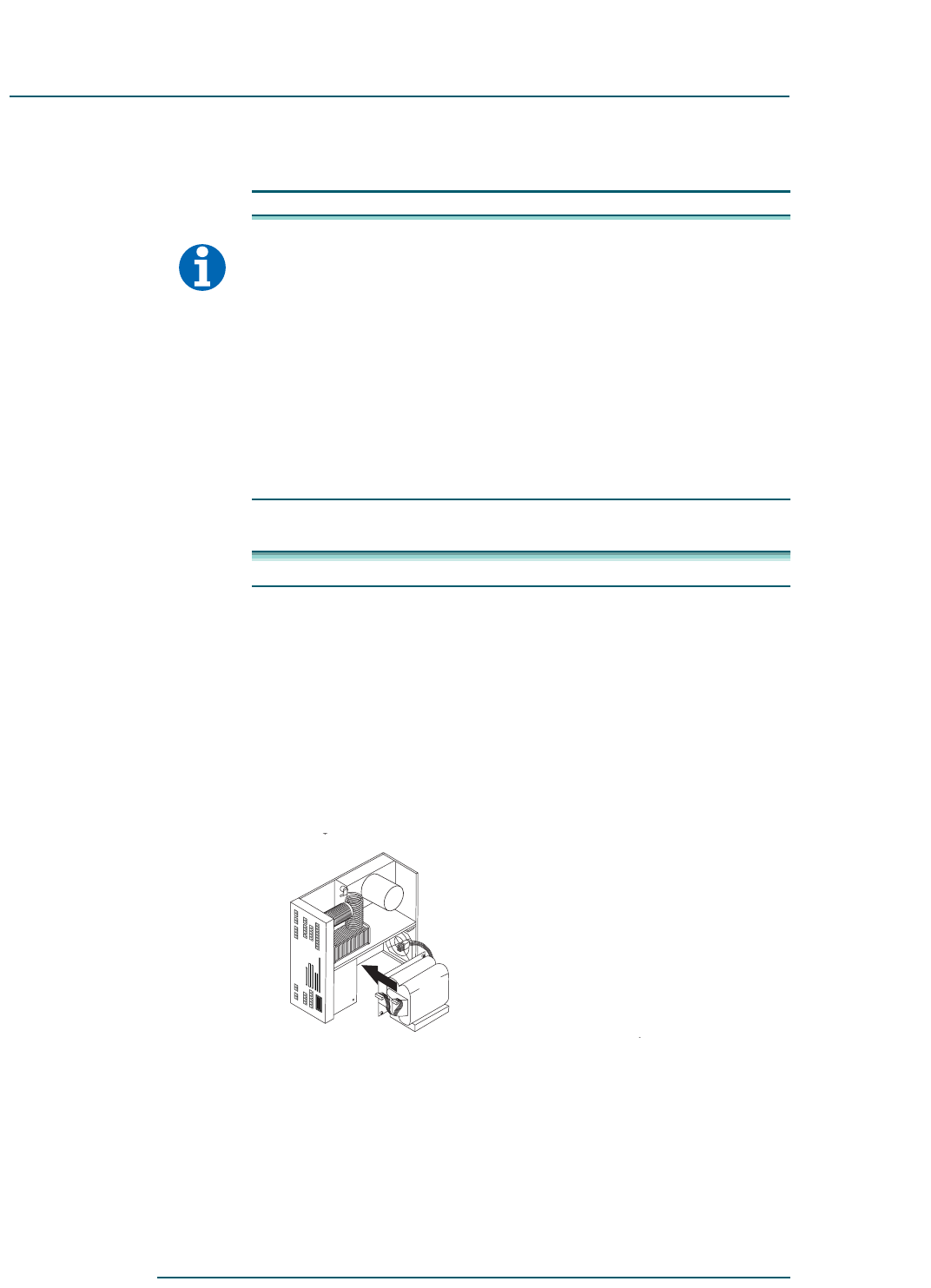
Step 2 Slowly move the amplifier and transformer together, aligning the nuts on
the transformer with the screw holes on the bottom of the amplifier.
Figure 4-3 Moving amplifier and transformer together
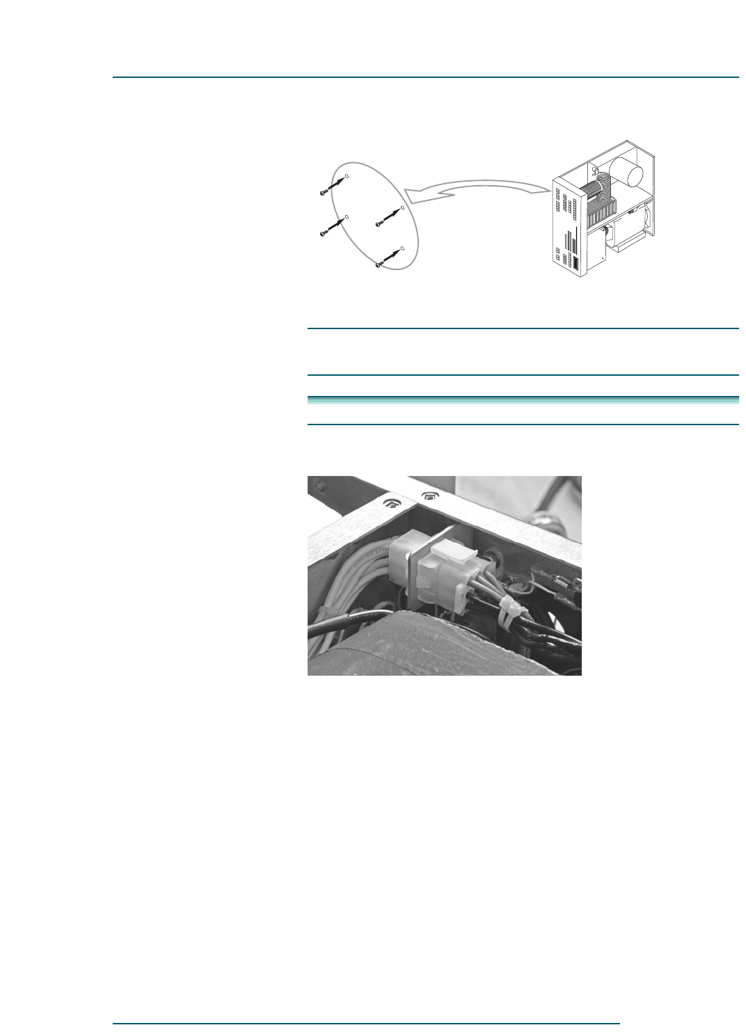
Step 3 Secure the transformer into place from the bottom of the amplifier by
inserting the supplied bolts (1/4/20 ½-inch hex bolts) with ¼-inch
washers through the four clearance holes in the chassis and into the nuts
in the transformer base.
Alpha 9500 Linear Amplifier User Manual RF Concepts, LLC
Setting Up the Amplifier Product Release 1
DOCNUMBER 9500
Document Issue 1.1
Page 4–4 February 2010
44
4
Figure 4-4 Securing transformer
Step 4 Carefully rotate the amplifier back to its standard orientation.
4.3 Connect the Transformer
Procedure 4-3 Connect the transformer
Step 1 Connect the transformer to the chassis.
Figure 4-5 Connecting transformer to chassis
1a Align the transformer’s Molex plug with the connector at the back of
the amplifier.
1b Push to connect them so that they are fully mated.
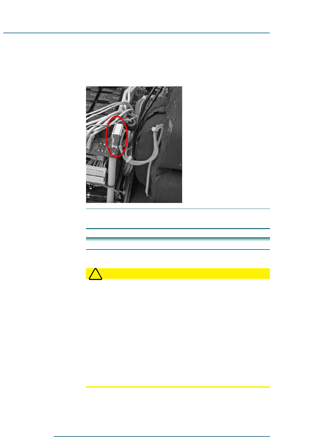
Step 2 Connect the transformer to the amplifier’s high-voltage (HV) board (the
lower of the two boards).
2a Locate the transformer’s 7-pin HV connector. Move the 2-pin mains
connector out of the way as needed to do so.
44
4
DOCNUMBER 9500
Document Issue 1.1
February 2010 Page 4–5
RF Concepts, LLC Alpha 9500 Linear Amplifier User Manual
Product Release 1 Setting Up the Amplifier
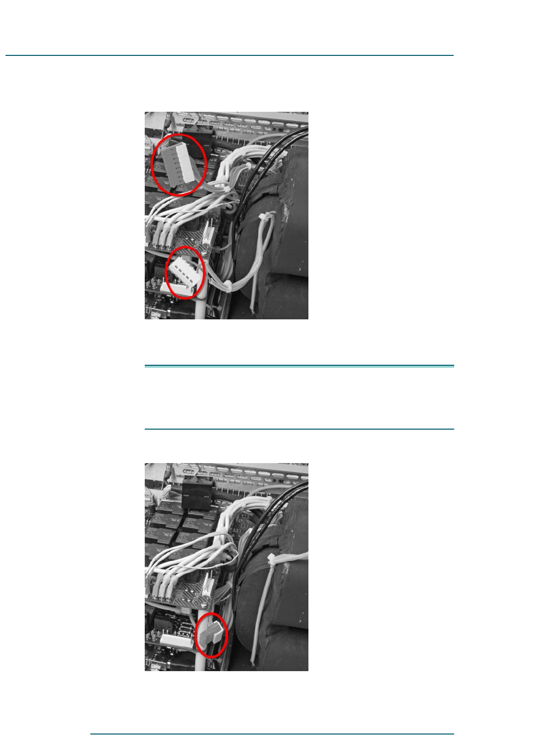
Figure 4-6 Transformer’s 7-pin HV connector (top) and 2-pin mains
connector (bottom)
2b Carefully route the transformer’s HV connector below all of the other
bundled wires.
NOTE:
•Do not bump or bend components on either board.
•Do not allow the HV wiring to touch any of the upper circuit board.
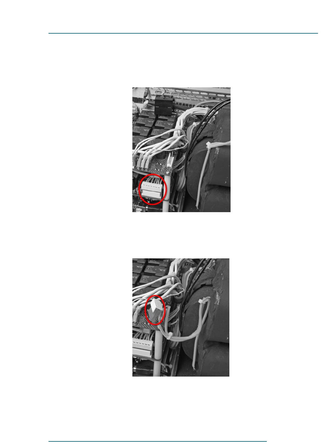
Figure 4-7 Routing transformer’s HV connector
Alpha 9500 Linear Amplifier User Manual RF Concepts, LLC
Setting Up the Amplifier Product Release 1
DOCNUMBER 9500
Document Issue 1.1
Page 4–6 February 2010
44
4
2c Align the transformer’s HV connector with the amplifier’s HV board
connector, with all pins in their appropriate slots, then gently but
firmly push the connectors together so that they are fully mated.
Figure 4-8 Connecting transformer to the HV board
Step 3 Connect the transformer to the amplifier’s mains board (the upper of the
two boards).
3a Locate the transformer’s 2-pin mains-board connector.
Figure 4-9 Transformer’s 2-pin mains-board connector
3b Locate the respective 2-pin connector on the amplifier’s mains board.
44
4
DOCNUMBER 9500
Document Issue 1.1
February 2010 Page 4–7
RF Concepts, LLC Alpha 9500 Linear Amplifier User Manual
Product Release 1 Setting Up the Amplifier
3c Align the connectors with both pins in their appropriate slots, then
gently but firmly push the connectors together so that they are fully
mated.
Figure 4-10 Connecting transformer to mains board
4.4 Connect the Cables
Procedure 4-4 Connect the cables
Step 1 Connect the power cord.
WARNING
!
WARNING! To avoid the hazard of a potentially fatal electric shock
and/or severe damage to the Alpha 9500 and other equipment:
•NEVER operate the amplifier with the cover removed.
•ALWAYS use an AC plug that is appropriate for the primary mains
voltage, current rating, and configuration.
•ALWAYS use grounding type AC connectors that conform to local codes.
•NEVER use 120-VAC plugs to connect to power receptacles for
190–250 V circuits.
•ALWAYS connect ALL station equipment to a good common ground.
Failure to do so may allow RF feedback to leak into the transceiver and
cause severe signal distortion.
Alpha 9500 Linear Amplifier User Manual RF Concepts, LLC
Setting Up the Amplifier Product Release 1
DOCNUMBER 9500
Document Issue 1.1
Page 4–8 February 2010
44
4
CAUTION
!
CAUTION! We strongly recommend that you operate the amplifier
on 240 VAC. If you choose not to heed this recommendation, see a
discussion of the limitations of doing so in Section 3.2, “Limitations of
Operation at 90–130 VAC,” page 3–3.
1a Connect the green wire in the amplifier power cable only to the AC
mains safety ground (or to neutral, as may be necessary with a 240-V
circuit configured 120V-N-120V without a separate ground,
commonly found in the US).
1b Connect the black-and-white power cord wires to the two hot wires
of the AC source. Either wire may be connected to either side of the
line. For best results, use a dedicated 200–240 V branch circuit of #10
AWG copper wire or equivalent, rated at 20 A, to feed the amplifier.
1c Connect the ground stud with wing nut on the rear of the chassis to a
good RF earth ground, such as a copper water pipe or driven rod, via
heavy copper braid or strap.
Step 2 Adjust the 8877 tube and exhaust chimney.
2a Ensure that the 8877 tube is firmly seated in its socket.
2b Ensure that the silicon-rubber exhaust chimney is straight and that it
is fully and correctly installed so that the bottom of the chimney is
firmly against the tube deck and completely covers the airflow
opening in the deck. Tube cooling exhaust must exit only through the
tube anode fins; it must not be allowed to escape outside them.
Failure to ensure proper cooling airflow may result in tube damage or
destruction, which is not covered under warranty.
2c Ensure that the anode connector is tightly clamped to the 8877 tube.
Step 3 Replace the amplifier cover and all attachment screws.
Use only the 6-32 screws supplied with the amplifier and do not tighten
any of the screws until all are started.
WARNING
!
WARNING! Do not attempt to operate the amplifier with the cover
removed or placed on the unit without the attachment screws. Doing
so damages the Alpha 9500 and may also cause injury or death to the
operator.

44
4
DOCNUMBER 9500
Document Issue 1.1
February 2010 Page 4–9
RF Concepts, LLC Alpha 9500 Linear Amplifier User Manual
Product Release 1 Setting Up the Amplifier
Step 4 Place the amplifier in its operating position on a stable surface with
sufficient space to the rear, sides, and top to allow good air flow and safe
placement of cables.
Step 5 Connect the amplifier RF INPUT to the transceiver RF OUTPUT.
Use 50-ohm coaxial cable-RG-58C/U or equivalent.
Step 6 Connect the amplifier RF OUTPUT to the antenna or appropriate
matching device.
Use RG-8A/U, RG-213/U, or equivalent high-quality cable with a PL-259
UHF-type plug on the amplifier end. Do not use RG8X cable, because it
is not rated for 1500 W.
Step 7 Connect the transceiver (T/R) control cable to the amplifier’s KEY IN
input.
The amplifier has a full break-in vacuum relay QSK system that requires
only the normal interconnection when used with a modern QSK
transceiver. The amplifier requires a contact closure (short circuit) on
transmit from the transceiver’s RELAY jack center pin to the chassis.
This function is supplied by the transceiver, usually from a dedicated
relay that is normally open in receive and closed in transmit.
7a Use shielded wire for the T/R control cable. Fit the amplifier end with
a common phono (RCA-type) plug and the transceiver end with a
suitable connector.
7b Ensure that the T/R relay contact closes. Protection circuitry prevents
hot-switching when RF drive is applied. Modern transceivers have
the proper time delay between key-up and the start of the transmitted
signal to allow the amplifier to follow the CW keying.
If you suspect a T/R timing problem:
1. Connect the CW keyer to the amplifier’s KEY IN input.
2. Connect a cable from KEY OUT on the amplifier to the keying
input of the transmitter.
3. Ground the key cable (they should key up).
4. Apply power from the transmitter. The amplifier should respond
with power out to the antenna.
NOTE: The amplifier does not generate or use Automatic Level
Control (ALC) voltages to control an exciter.

Alpha 9500 Linear Amplifier User Manual RF Concepts, LLC
Setting Up the Amplifier Product Release 1
DOCNUMBER 9500
Document Issue 1.1
Page 4–10 February 2010
44
4
4.5 Set the Input Drive
You must set the transceiver output power properly. Virtually all damage
to date has resulted directly from severe overdrive. The amplifier requires
50-W drive for full rated output.
Damage caused by applying several-times-rated drive power to the
amplifier is not covered under warranty. Fortunately, most modern
transceivers maintain quite consistent output from band-to-band and
mode-to-mode when set up properly.
Some transceivers may produce RF spikes upon keying during SSB
operations. Do not operate the amplifier with transceiver power controls
set at full power output. Do not rely on the mic gain control to set power.
Rather, set up the transceiver with proper mic gain and processor levels at
normal power level to drive the amplifier (typically 50 W).
CAUTION
!
CAUTION! Some transceivers may experience RF spikes during
keying for SSB operations. To avoid these spikes, do not operate the
amplifier with transceiver power controls set at full power output and
do not rely on the mic gain control to set power. Rather, set up the
transceiver with proper mic gain and set processor levels at normal
power level sufficient to drive the amplifier (normally 50 W).
4.6 Connect the Transceiver Keying Line
Procedure 4-5 Connect the transceiver keying line
Step 1 Connect the transceiver keying line.
The following is a list of popular transceivers and considerations for their
connection to the amplifier. For advice on other transceivers, contact RF
Concepts as described in Chapter 1, “Introduction.”
Table 4-1 Popular transceivers
Transceiver Connection and keying information
Icom RF —
T/R — Connection with the “Send” jack. For
information, see the transceiver user manual.
Kenwood RF —
T/R — For information on connecting to external
amplifiers, see the transceiver user manual.

44
4
DOCNUMBER 9500
Document Issue 1.1
February 2010 Page 4–11
RF Concepts, LLC Alpha 9500 Linear Amplifier User Manual
Product Release 1 Setting Up the Amplifier
Step 2 (Optional) Enable the transceiver automatic antenna tuner.
Many popular transceivers have built-in antenna tuners. Although a tuner
is not usually needed when driving your amplifier, you may use it with
care through the amplifier.
For instructions, see the transceiver user manual.
Yaesu RF —
T/R — Connection with the RCA “TX GND” connector
and/or DIN “Band Data” connector. For information,
see the transceiver user manual.
Older
transceivers
For information on connecting to external amplifiers,
see the transceiver user manual.
Table 4-1 Popular transceivers (Continued)
Transceiver Connection and keying information

Alpha 9500 Linear Amplifier User Manual RF Concepts, LLC
Setting Up the Amplifier Product Release 1
DOCNUMBER 9500
Document Issue 1.1
Page 4–12 February 2010
44
4

RF Concepts, LLC
Product Release 1 5
DOCNUMBER 9500
Document Issue 1.1
February 2010 Page 5–1
5 Operating the Amplifier
5.1 Principles of Operation 5–1
5.2 Start Up the Amplifier 5–5
5.3 Tune the Amplifier 5–7
5.4 Program the Amplifier Memory 5–10
5.5 Operate the Amplifier 5–12
5.1 Principles of Operation
Once your Alpha 9500 linear amplifier is set up as described in the
previous chapters, before first use you must tune it for peak RF output and
lowest current for the selected antenna port over the range of band
segment frequencies to be used. At that point it is ready for use.
The Alpha 9500 can be operated in autotune mode (using factory-default
values stored in default memory) or tuned using values that you store in
user memory.
Basic operation The amplifier is initially tuned at the factory with default tuning values in
default memory and two user memories, designated User 1 and User 2.
These values are appropriate for a pure 50-ohm load but should work for
any band segment with voltage standing-wave ratios of SWR ≤ 1.5:1.
For normal use, do the following:
•For SWR ≤ 1.5:1, tune using the default values.
•For SWR > 1.5:1 or if you do not achieve good results with the
default values, tune manually or using autotune and save the new
tuning values for each band segment in User 1 or User 2 memory for
future use.
NOTE: For SWR between 2.0:1 and 3.0:1, manual tuning using
the load and tune controls may be required and full output
may not be achieved.
You can select different antenna ports for use with different band
segments. The next time you use the amplifier, when you select a band
segment, the amplifier returns automatically to the last port used for that
segment. If you ever use other than the default port, then, each time you
use the amplifier you should check the port setting and change it if
necessary to the correct port.

Alpha 9500 Linear Amplifier User Manual RF Concepts, LLC
Operating the Amplifier Product Release 1
DOCNUMBER 9500
Document Issue 1.1
Page 5–2 February 2010
55
5
When powered on, the amplifier tunes to the last-used band segment using
memory values. You can select a different band segment manually or
apply low input power to select a new band segment.
After you have set up your user memories, during normal operation, you
need only select the desired tuning mode (Default, User 1, or User 2) and
band and band segment, or key the amplifier (10–20 watts) to select the
band and band segment, then increase input power to achieve full output.
You are now ready to operate. If you must manually tune or autotune,
something has probably changed in the antenna system and you may need
to reprogram a user memory. It is generally safest to program and operate
from user memories. If you have not saved to the user memories, they still
contain factory default values.
Operational states The Alpha 9500 can be in one of seven operational states, listed in
Table 5-1.
Table 5-1 Operational states
State Description
Off Plugged in but OFF.
To enter this state: Plug the amplifier into the AC line supply.
In this state: The front panel lights briefly illuminate, then turns off and the entire
front panel goes dark. (If the lights stay on, unplug the AC connector for a few
seconds and plug in again. the amplifier has an internal auxiliary 5V power supply
that is on.) All microprocessors are powered up and communicating with one
another. The USB and RS232 ports are active.
On 1 Operating with the exciter only, without tube heater or HV.
To enter this state: Press the ON/OFF (ANT SEL) button or send a command
from the serial interface.
In this state: The internal frequency counter is active and automatically switches
antennas when you transmit. Forward power and SWR are indicated on the digital
meter and the bar graphs.
Use this state when you need to access the antenna switch function but you are using
only exciter input power. The portions of the front panel display that are appropriate
in this mode are enabled and others are disabled.

55
5
DOCNUMBER 9500
Document Issue 1.1
February 2010 Page 5–3
RF Concepts, LLC Alpha 9500 Linear Amplifier User Manual
Product Release 1 Operating the Amplifier
On 2 (warmup) Tube is warming up and HV is present.
To enter this state: Press the ON AMP button or send a command from the serial
interface.
In this state: The AC line is connected to the primary of the transformer and all
amplifier voltages are present (including the high voltage for the tube plate). The
stepper motors may turn briefly; they sound like a low growl.
A 3-minute warmup countdown begins. The amplifier cannot move to a higher state
until the countdown timer reaches 0. To see the number of seconds remaining, tap
the FLT button and watch the digital meter.
During warmup, we recommend that you check the plate voltage by tapping the Vp
button. The digital meter should read in the range 3400–3650.
Standby Tube is ready and amplifier is in bypass mode (exciter only).
To enter this state: Wait for the amplifier to complete its 3-minute warmup.
In this state: The exciter can use the antenna, but the amplifier does not amplify the
signal. Certain faults cause the amplifier to return to this mode.
Unkeyed Key-in has not been asserted.
To enter this state: Wait for the amplifier to complete its 3-minute warmup and
press the OPER button. Or issue the command for the OPER mode from the serial
interface.
In this state: The amplifier is fully warmed up, but the key-in line has not been
activated. The tube is biased to a very low current and the exciter is still connected
to the antenna.
Keyed, no RF Key-in has been asserted, but no RF is sensed.
To enter this state: Wait for the exciter to short the key-in line to ground.
In this state: The input and output relays are activated and the exciter is connected
to the tube input.
Power Amplifier is keyed, RF has been sensed, and the amplifier delivers power.
To enter this state: Wait for the amplifier to sense RF.
In this state: The tube is biased to its operational condition. The amplifier measures
the RF frequency and attempts to match its operational condition to the drive
frequency and power that it senses. If the frequency of the input signal indicates that
a band change is needed, the amplifier briefly unkeys to avoid damage to the
bandswitch. Antenna-select features are disabled to avoid hot-switching of relays.
The amplifier is now fully operational and delivering power to the load.
Table 5-1 Operational states (Continued)
State Description

Alpha 9500 Linear Amplifier User Manual RF Concepts, LLC
Operating the Amplifier Product Release 1
DOCNUMBER 9500
Document Issue 1.1
Page 5–4 February 2010
55
5
Tuning modes You can tune the amplifier in one of three tuning modes—Default, User
1, or User 2—and from any of these proceed to autotune mode..
Table 5-2 Tuning modes
Mode Description
Default By default, when the amplifier is first powered on or QSYed, it retunes using factory-
supplied tuning values. These values are derived for a load with voltage standing-
wave ratio SWR = 1.0:1, so the amplifier will be tuned with a different tuning value
from default memory for each segment of each band. For SWR ≤ 1.5:1, the default
tuning values are usually appropriate. For SWR > 1.5:1, some manual tuning may be
required using the tune and load controls. The antenna port last used in Default mode
for a particular band and band segment is used.
User 1/User 2 In User 1 or User 2 mode, the amplifier tunes (autoselects) from values stored in User
1 or User 2 memory. As in Default mode, the amplifier retunes at powerup or when
it is QSYed to a different band segment. Initially (from factory), the user memories
are programmed with factory-default values, which are retained until they are
overwritten by new tuning values saved to a band segment. The antenna port is the
last one used for that user memory on that band and segment. If for some reason the
amplifier is not correctly tuned, you can tune it manually using tune and load
controls, and the new value is then stored in user memory.
When you switch among Default and User 1/User 2 modes, the amplifier tunes to the
values stored in the newly selected memory. Programming a user memory overwrites
any previous values, and default values are lost from user memory for a specific band
segment. You can view the default values through the computer connection to the
amplifier.
If you have two antennas that operate on the same band, store separate values in User
1 and User 2 memories. The antenna port selection is determined by the last used
antenna on that band segment.

55
5
DOCNUMBER 9500
Document Issue 1.1
February 2010 Page 5–5
RF Concepts, LLC Alpha 9500 Linear Amplifier User Manual
Product Release 1 Operating the Amplifier
Faults In the event of a fault, the tube biases off, the relays are placed in bypass
mode, and RF from the amplifier goes directly to the antenna. The FLT
(Fault) switch lights and the 7-segment display shows the number of the
last recorded fault.
!
IMPORTANT Do not turn the amplifier off. To clear a fault:
•For a gain fault, wait for the amplifier to reset itself.
•For all other faults, resolve the fault as described in Section 8.2,
“Fault Codes and Resolutions.” Then press the left ON button to
release the fault and press the OPER button to continue.
5.2 Start Up the Amplifier
Procedure 5-1 Start up the amplifier
Step 1 Install and set up the amplifier as described in the preceding chapters.
Step 2 Power up the amplifier by pressing one of the two ON buttons:
•ON/OFF (ANT SEL) button
This provides initial power to the metering, band, and segment-
selection circuits, which turns on the wattmeter and antenna-selection
functionality (ON1 setting). When you then pass RF through and key
Auto In autotune mode, which you select when the amplifier is in User 1 or User 2 mode,
the amplifier initially tunes from stored values and then automatically tweaks the
tuning when power is applied. The amplifier tunes on the fly and hunts for an
optimum tuning point as you change frequency. However, depending on load
conditions, you may need to turn off autotune mode and tweak the tuning yourself
with the load and tune controls. The currently selected antenna port is used.
Be sure to save the results of autotuning into the user memory by pressing the SAVE
button. When you switch out of autotune mode, the amplifier holds the tuning unless
you press Default or User 1/User 2, in which case it returns to the memory values for
those modes.
Note that autotuning the amplifier is different from autoselecting a band and band
segment. In normal operation, when the amplifier is keyed, it autoselects the correct
band and segment without your intervention, although you can overrule it by
manually selecting a band segment. Autotuning, on the other hand, is initiated only
when you press the Auto button to put the amplifier in autotune mode.
Table 5-2 Tuning modes (Continued)
Mode Description

Alpha 9500 Linear Amplifier User Manual RF Concepts, LLC
Operating the Amplifier Product Release 1
DOCNUMBER 9500
Document Issue 1.1
Page 5–6 February 2010
55
5
the amplifier, the amplifier autoselects a band and segment. You can
pass up to 1500 W through the amplifier in bypass or the ON1 setting.
•ON (AMP) button
This duplicates the functions described above, and also applies high
voltage to the tube. The amplifier begins its warmup countdown
sequence and the 7-segment display shows the seconds remaining in
the countdown. The STBY switch light blinks.
Step 3 Monitor amplifier parameters:
•Display amplifier parameters by pressing the associated button that
controls the 7-segment display. For information on these buttons, see
Section 2.3, “Controls and Display,” page 2–3.
•Display the plate voltage by pressing the Vp button. The value should
be about 3545 V. If the value is....
•<3300 V: Check your outlet, plug wiring, and equipment
grounding in your shack. If power is variable or unstable, you can
force the amplifier to always choose a particular tap setting. For
information on how to do so, contact RF Concepts technical
support.
•>3800 V: Ensure that the correct primary tap is being selected. If
autotap-selection is disabled, try enabling it. If the highest tap is
being used, your line voltage is likely >250V; talk to your power
company about reducing it.
To return to the countdown display, press the FLT (Fault) button.
Step 4 Proceed to Section 5.3, “Tune the Amplifier,” page 5–7.
NOTE During warmup and operation, do not press the MEMORY/AUTO
button. The amplifier performs automatic frequency detection, band-
tuning, and antenna selection independently of this button. Rather,
use this button to assist with initial tune and load settings as
described in Section 5.3, “Tune the Amplifier,” page 5–7.

55
5
DOCNUMBER 9500
Document Issue 1.1
February 2010 Page 5–7
RF Concepts, LLC Alpha 9500 Linear Amplifier User Manual
Product Release 1 Operating the Amplifier
5.3 Tune the Amplifier
!
IMPORTANT •Do not attempt to tune the amplifier until you read this entire
section. Then follow instructions carefully.
•During any tuning operation, it is important that you monitor grid
current and gain. Even at SWR >2:0:1, where full output may not
be achieved, you must still keep grid current and gain within
limits. You normally should not need over ~60 W input to drive the
amplifier to full output.
The Alpha 9500 has an autotune feature for tuning to the desired
frequency. You can use this feature or turn it off and manually tune the
amplifier.
Your goal in tuning the amplifier is to maximize output power for a given
input power. At SWR > 2.0:1, this normally becomes difficult. You can
load a high SWR, but keep in mind as you approach full output that there
is great stress on the transmission line, connectors, and antennas. If you
use an antenna tuner, also keep in mind that high voltages and circulating
currents may exist between the tuner (also inside the tuner) and the
antenna even though the amplifier sees a good load.
Remember
REMEMBER A properly tuned amplifier has the following properties:
•Full legal power output. For voltage SWR <2.0:1 this is 1500 W
(with 40–60 W drive). For SWR > 2.0.1, full power may not be
possible but the other tuning indications are the same.
•Grid current in green zone (normally 40 mA; at >100 mA, the
system alarms)
•Gain indication in green zone
•Plate current in green zone (1 A at 1500 W; at >1.2 A, the system
alarms)
(Optional) Changing
antenna settings You can optionally change to other than the default antenna or use two
antennas simultaneously.
Procedure 5-2 (Optional) Change the antenna settings
Step 1 Start up the amplifier as described in “Start Up the Amplifier,” page 5–5.
Step 2 To change the default antenna to a different port for all User 1/User 2
memory bank settings:
2a Press User 1 or User 2 so that the memory light is on.

Alpha 9500 Linear Amplifier User Manual RF Concepts, LLC
Operating the Amplifier Product Release 1
DOCNUMBER 9500
Document Issue 1.1
Page 5–8 February 2010
55
5
2b Press the desired antenna port twice.
2c While the antenna light is blinking, press the SAVE button.
The new antenna port value is now spread across all bands and segments
on User 1 or User 2.
Step 3 To listen (and transmit) on two antennas simultaneously:
3a Press the ANTENNA SELECT button for the first desired antenna
twice.
3b While the light is blinking, press the button for the second desired
antenna.
Both antenna lights should now be on and both antennas open for listening
and transmitting. The SWR is determined by the parallel combination of
the two antennas.
Step 4 Proceed to either “Autotuning,” page 5–8 or “Manual tuning,” page 5–9.
Autotuning Use autotune during initial setup to find correct tuning values.
NOTE •We recommend that you use user memories rather than
autotuning for normal operation.
•If you use autotuning for normal operation, hunting behavior
usually indicates instability in the antenna or feed system. Repair
the antenna or feed system so that you can operate from fixed
tuning.
•Autotuning may give slightly different tuning values when the
amplifier is retuned due to the existence of a small tuning dead
zone.
Procedure 5-3 Autotune the amplifier
Step 1 Start up the amplifier as described in “Start Up the Amplifier,” page 5–5.
Step 2 If necessary, select the antenna port for the desired band.
NOTE: If you operate on other than the default antenna port (port 4)
for one or more bands, you must manually select the port before
keying the amplifier on that band. To select the port, press the
ANTENNA SELECT button for the desired antenna port. The amplifier
stays on that port until you change the band segment. If you wish to
return to the same tuning settings, save the settings into memory.
When you return, the antenna port goes to the one last used for that
segment.

55
5
DOCNUMBER 9500
Document Issue 1.1
February 2010 Page 5–9
RF Concepts, LLC Alpha 9500 Linear Amplifier User Manual
Product Release 1 Operating the Amplifier
Step 3 Set the transceiver to the desired band/segment frequency.
Step 4 Select User 1 or User 2 mode (so that you can save the settings).
Step 5 Press the MEMORY/AUTO button to turn on autotune.
Step 6 Key the transceiver by applying input power of 10–20 W.
The amplifier selects the specified band and autotunes.
Step 7 With the amplifier keyed, slowly advance the transceiver power.
As you increase the power, the amplifier continues to tune.
Step 8 (For initial amplifier setup) When you reach the desired output power
level, unkey the amplifier and press the SAVE button once.
The Save LED blinks on and off once. The tuning settings are now
associated with the indicated band/segment. From now on, each time you
are in User 1/User 2 memory, when you key the amplifier and apply RF
in that range of frequencies, the amplifier autoselects these saved settings.
Step 9 Repeat the previous steps for all band segments.
Step 10 Press the MEMORY/AUTO button again to turn off autotune.
Step 11 (Optional) Verify the saved settings by returning to each frequency and
confirming the power output. Make any necessary adjustments and save
as before.
Step 12 Proceed to “Program the Amplifier Memory,” page 5–10.
NOTE After you set up your amplifier with reasonable tune and load settings,
do not press the MEMORY/AUTO button. Small changes in
frequency and antenna performance are handled easily within the
amplifier tuning range.
Manual tuning Use manual tuning as necessary to optimize amplifier performance.
Procedure 5-4 Manually tune the amplifier
Step 1 Start up the amplifier as described in “Start Up the Amplifier,” page 5–5.
Step 2 Select a band segment either with autoselect or manually.
Step 3 If necessary, select an antenna port.
If you operate on other than the default antenna port (port 4), you must
manually select the port. The port that was last used is saved.
Step 4 Key the amplifier by applying input power of 10–20 W.

Alpha 9500 Linear Amplifier User Manual RF Concepts, LLC
Operating the Amplifier Product Release 1
DOCNUMBER 9500
Document Issue 1.1
Page 5–10 February 2010
55
5
Step 5 Move the tune and load controls carefully, in small steps, until you
maximize (that is, achieve full rated) output power.
As you do so, monitor grid current and gain to keep them in the proper
ranges.
Step 6 Save the tuning values in one of the user memories.
Step 7 Continue the process for all band segments of interest.
Step 8 Proceed to “Program the Amplifier Memory,” page 5–10.
5.4 Program the Amplifier Memory
The Alpha 9500 has 5 memory settings per band per user (Default, User
1, and User 2). Each memory setting holds 3 values: frequency, tune, and
load.
These capacitor settings are made at the factory by tuning into a 50-ohm
load, saving the settings, and migrating them to the appropriate memory
bank. The amplifier is thus set up at the factory so that the memory-bank
tune and load settings across all bands and band segments are appropriate
for 1500-W output into a 50-ohm load on antenna port 4 for User 1 and
User 2.
Antenna port 4 is the default output port for all memories on initialization.
We recommend that you choose antenna port 4 for your primary antenna
on User 1. If no antenna is connected or the wrong port is selected, you
get a voltage SWR fault (Fault 12).
The default memory settings are the only ones that cannot be changed
(except at the factory). They are listed in Table 5-3.
Table 5-3 Factory-set memory settings by band and segment
Band Seg 1 Seg 2 Seg 3 Seg 4 Seg 5
28 28.20 28.60 29.00 29.40 29.80
24 24.55 24.65 24.75 24.85 24.95
21 21.05 21.15 21.25 21.35 21.45
18 18.05 18.15 18.25 18.35 18.45
14 14.05 14.15 14.25 14.35 14.45
10 10.05 10.15 10.25 10.35 10.45
7 7.05 7.15 7.25 7.35 7.45
3.5 3.55 3.65 3.75 3.85 3.95
1.8 1.82 1.84 1.90 1.94 1.98

55
5
DOCNUMBER 9500
Document Issue 1.1
February 2010 Page 5–11
RF Concepts, LLC Alpha 9500 Linear Amplifier User Manual
Product Release 1 Operating the Amplifier
You are expected to optimize the capacitor settings stored in User 1/User
2 memories during installation.
Procedure 5-5 Program the amplifier memory
Step 1 Start up and tune the amplifier as described in “Start Up the Amplifier,”
page 5–5 and “Tune the Amplifier,” page 5–7.
Step 2 Tune the amplifier to the desired frequency in the User 1/User 2 position
and the correct antenna port. Remember that you cannot store in the
default position.
Example: Tune to 14.025 MHz in User 1 segment 1.
Step 3 Press the SAVE button (to the left of the User 1/User 2 buttons).
Step 4 If you use more than one antenna for a band, repeat to store the additional
antenna information.
Example: You have one antenna on port 4 (beam) and another on port 3
(vertical) and both are resonant at 14 MHz. Store the beam settings in
User 1 antenna port 4 and the vertical settings in User 2 antenna port 3.
Step 5 Move off the band and ensure that the amplifier returns to the previous
location by pressing any other band button and rekeying the amplifier on
the just-programmed frequency. If necessary, save the value again.
Step 6 (Optional) To change the center frequency associated with a particular
segment in User 1/User 2:
6a Go to the desired frequency and key the amplifier.
6b While the amplifier is producing power, press the desired segment
button to save.
The current frequency from the transceiver is saved as the new center
frequency for the segment.
NOTE: Center frequencies for each band must increase in order
from 1 to 5 (segment 1 is the lowest and segment 5 is the
highest).
Step 7 Proceed to “Operate the Amplifier,” page 5–12.

Alpha 9500 Linear Amplifier User Manual RF Concepts, LLC
Operating the Amplifier Product Release 1
DOCNUMBER 9500
Document Issue 1.1
Page 5–12 February 2010
55
5
5.5 Operate the Amplifier
Procedure 5-6 Operate the amplifier
Step 1 Start up and tune the amplifier and program memory as described in “Start
Up the Amplifier,” page 5–5, “Tune the Amplifier,” page 5–7, and
“Program the Amplifier Memory,” page 5–10.
Step 2 Push the OPER button.
Although the amplifier tunes from memory when you key up with lower
power in either standby or operate states, for autotuning to work properly
you must be in one of the operate states.
Step 3 Select the correct antenna.
The amplifier starts initially with the default antenna port (port 4).
Step 4 Key the transceiver with the transceiver power output set as low as
possible.
Step 5 Apply RF.
The amplifier requires only about 50 W for full output. When the
amplifier is keyed and RF is applied, the following sequence occurs
automatically:
1. The controller jumps to the correct bandswitch position and
frequency segment (this is called autoselect).
2. The antenna setting changes to the last one used for that frequency on
that memory bank (Default, User 1, or User 2).
3. The tune and load capacitor settings change to the saved values for
that band segment.
This is the how the amplifier normally functions. If the amplifier has been
set up properly, no other user intervention is required.
Step 6 Monitor the grid current.
The amplifier operates in Class AB2 when delivering maximum output
power consistent with excellent linearity. A small amount of grid current
flows, which you can monitor via the grid-current bar graph. As overdrive
approaches, grid current increases rapidly and the red grid LEDs become
illuminated.
At maximum output and efficiency, the red grid LEDs should not be
illuminated. If they are illuminated before the desired value of plate
current and/or power output is reached, readjust amplifier loading before
continuing.
Step 7 Ensure that exhaust air is detectable from the exit vent holes above the
tube. If exhaust air is not detectable:

55
5
DOCNUMBER 9500
Document Issue 1.1
February 2010 Page 5–13
RF Concepts, LLC Alpha 9500 Linear Amplifier User Manual
Product Release 1 Operating the Amplifier
7a TURN OFF the amplifier immediately.
7b Ensure that the exhaust chimney is properly positioned over the tube.
7c Power up the amplifier again.
NOTE •If the amplifier faults, it usually resets itself after 4 seconds.
— To reset the amplifier manually if it fails to reset itself, push
ON/AMP and then OPR. (You need not turn the amplifier off.)
— To display the last fault, press the FLT button and view the 7-
segment display.
— To display the last 20 faults, open the AR9500 PC application
that allows remote control over a serial interface and select
the correct COM port. Select Tools > Get fault log.
To see a complete list of possible faults, see Chapter 8,
“Diagnosing Faults.”
•You can optionally control the Alpha 9500 completely from the
Microsoft® Windows® AR9500 PC application rather than the
front panel. For more information, see Chapter 6, “Operating the
Amplifier from a PC.”

Alpha 9500 Linear Amplifier User Manual RF Concepts, LLC
Operating the Amplifier Product Release 1
DOCNUMBER 9500
Document Issue 1.1
Page 5–14 February 2010
55
5

RF Concepts, LLC
Product Release 1 6
DOCNUMBER 9500
Document Issue 1.1
February 2010 Page 6–1
6 Operating the Amplifier from a PC
6.1 Set Up to Operate from a PC 6–1
6.2 Operate from the PC 6–2
The Alpha Remote (AR) AR9500 PC application allows you to access all
functions and features of the Alpha 9500 from your PC. From this
application you can view and use:
•A simulated front panel with all the buttons replicated, so that you can
click them just as if you were pushing the corresponding button on the
front panel
•Windows that show:
•The amplifier’s normal operational RF parameters
•All power supply voltages used in the amplifier
•The amplifier ID and serial numbers for all resident firmware
•The last 20 faults that the amplifier registered
•The band edges used by the amplifier
•The segment center frequencies
6.1 Set Up to Operate from a PC
Procedure 6-1 Set up to operate from a PC
NOTE •You can also establish communications with the amplifier via any
communications program such as hyperterminal. The
communications parameters for most COM ports are:
— 115,200 baud
— 8 data bits, 1 stop bit, no parity bit
— No flow control
— Straight-through cable
•The Alpha 9500 has both a 9-pin serial port and a USB port on
the back. Only one of these can be active at a time.

Alpha 9500 Linear Amplifier User Manual RF Concepts, LLC
Operating the Amplifier from a PC Product Release 1
DOCNUMBER 9500
Document Issue 1.1
Page 6–2 February 2010
66
6
Step 1 Locate the amplifier’s USB driver (filename CDM-setup.exe) from the
RF Concepts website or the CD supplied with the amplifier.
Step 2 Determine which PC COM port is assigned to the Alpha 9500.
The amplifier is normally assigned to COM port 4 or 5. Confirm this by
checking the computer properties and going to the PC’s Device Manager
to locate the COM ports.
Step 3 Download the AR9500 PC application (filename 9500_app.zip) from the
RF Concepts website and install it.
Step 4 When you first run the application, set up the correct COM port for the
application.
We recommend that you use the active COM port on the PC rather than
assigning a USB port as the COM port.
Step 5 When the application opens a window that shows graphically all of the
buttons and indicators that are on the front panel, verify that the
application is communicating with the amplifier by mousing over the
ON1 button and left-clicking on it.
If the amplifier does not turn on, verify that the COM port is set to the
correct number.
6.2 Operate from the PC
When the application opens, the main window and the front panel
windows are displayed.
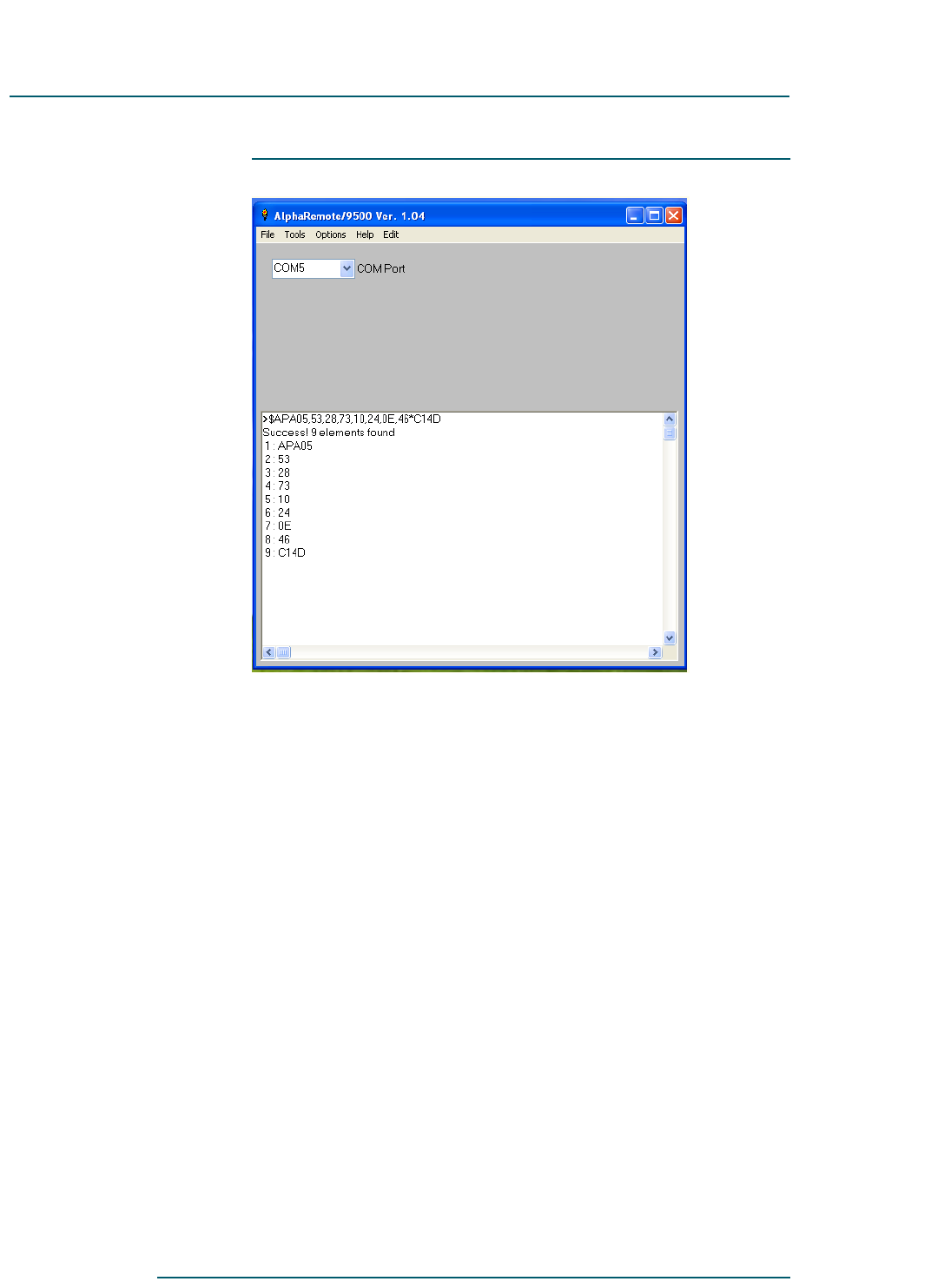
66
6
DOCNUMBER 9500
Document Issue 1.1
February 2010 Page 6–3
RF Concepts, LLC Alpha 9500 Linear Amplifier User Manual
Product Release 1 Operating the Amplifier from a PC
Main window
From the main window you can:
•View a list of available COM ports from the drop-down menu labeled
COM Port. Scroll through the list until the port connected to your
amplifier is highlighted.
•View the text editor box at the bottom of the window, which shows
messages about the data being received from the amplifier.
•View the drop-down windows at the top. Below the menus is a list
box for COM port setup.
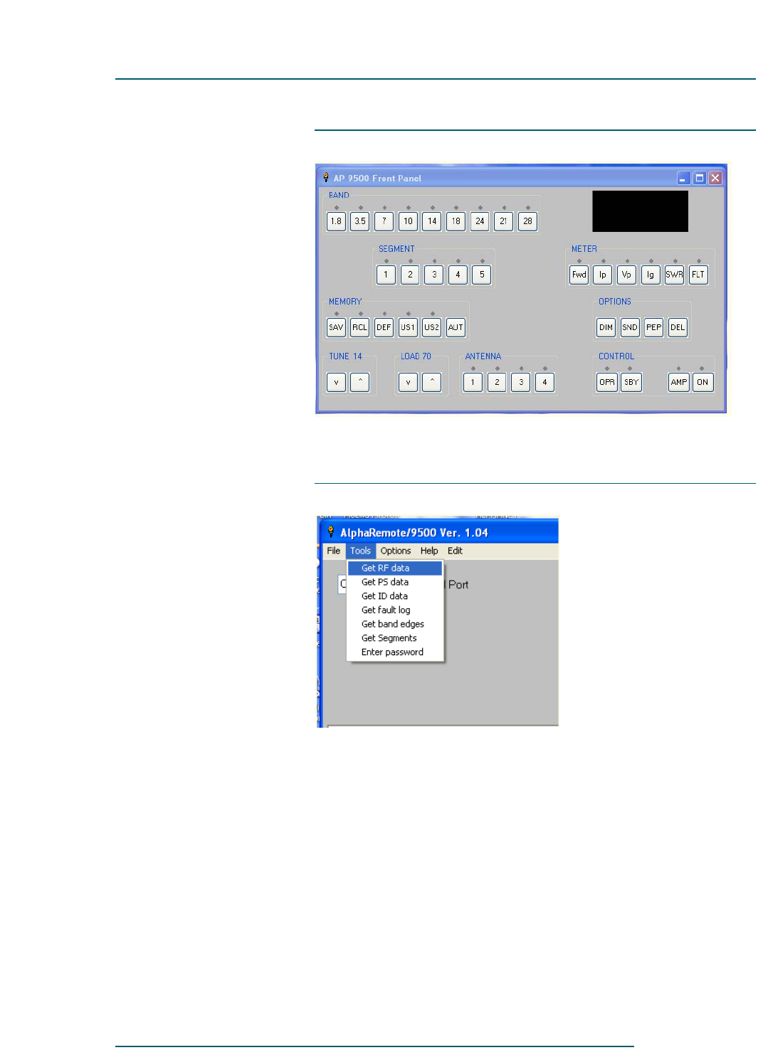
Alpha 9500 Linear Amplifier User Manual RF Concepts, LLC
Operating the Amplifier from a PC Product Release 1
DOCNUMBER 9500
Document Issue 1.1
Page 6–4 February 2010
66
6
Simulated front panel
From the simulated front panel you can click any button just as you would
press the button from the amplifier itself.
Tools menu
From the Tools menu you can obtain various types of information.
Clicking this selection sends a telemetry request to the amplifier asking
for that type of data. When the data is received, a window automatically
opens to show what the amplifier sent back. Each time this option is
selected, the information in the window is updated. You can get:
•Radio frequency (RF) data
•Power supply (PS) data
•ID and firmware data
•Fault log of the last 20 fault conditions
•Band edges
•Segment center frequencies
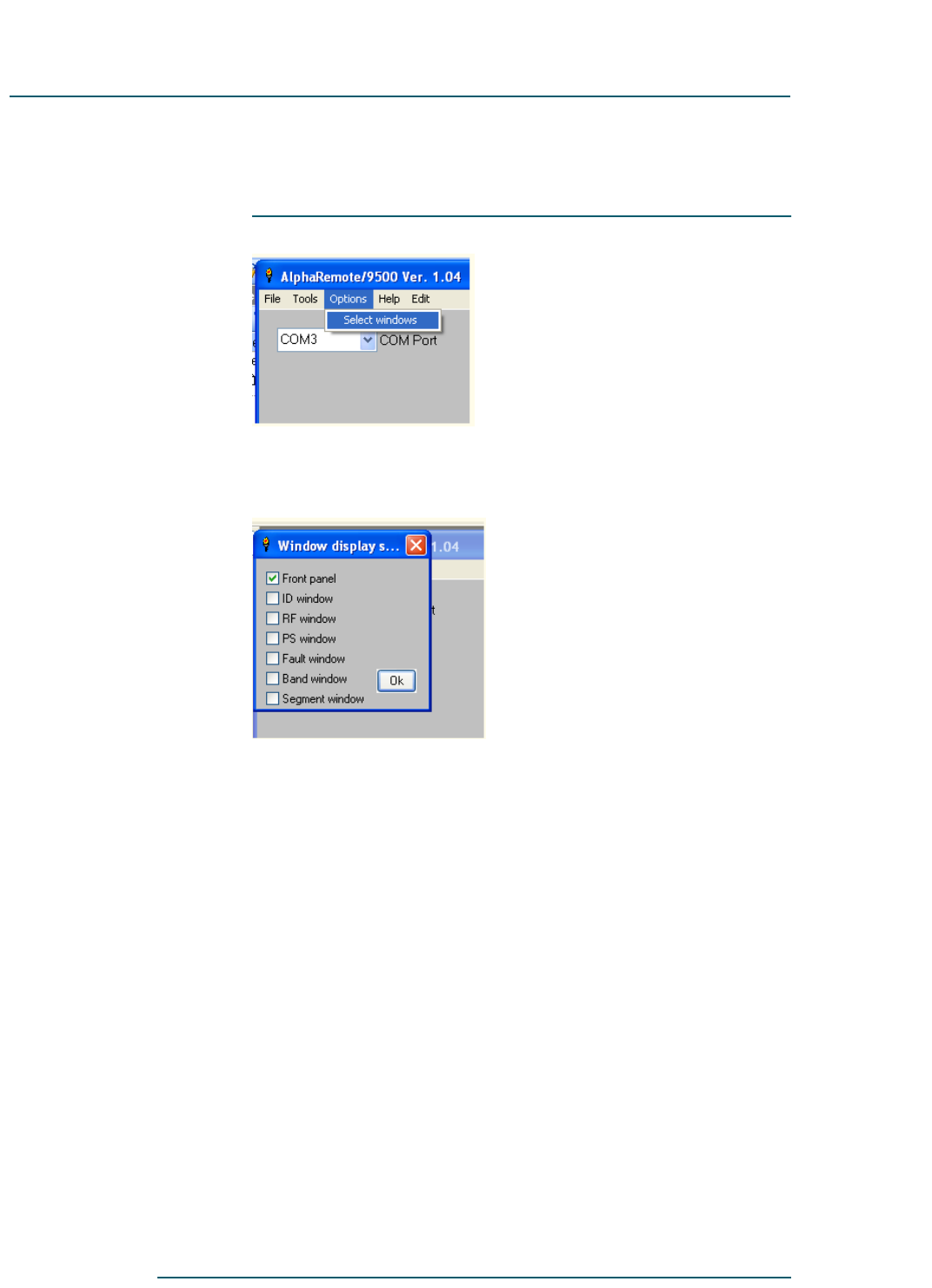
66
6
DOCNUMBER 9500
Document Issue 1.1
February 2010 Page 6–5
RF Concepts, LLC Alpha 9500 Linear Amplifier User Manual
Product Release 1 Operating the Amplifier from a PC
Whether or not any of this data is displayed is controlled by options
selected in the Options menu.
Options menu
From the Options menu, if you Select Windows, the following menu
appears.
From this window you can select which parameters to display.

Alpha 9500 Linear Amplifier User Manual RF Concepts, LLC
Operating the Amplifier from a PC Product Release 1
DOCNUMBER 9500
Document Issue 1.1
Page 6–6 February 2010
66
6
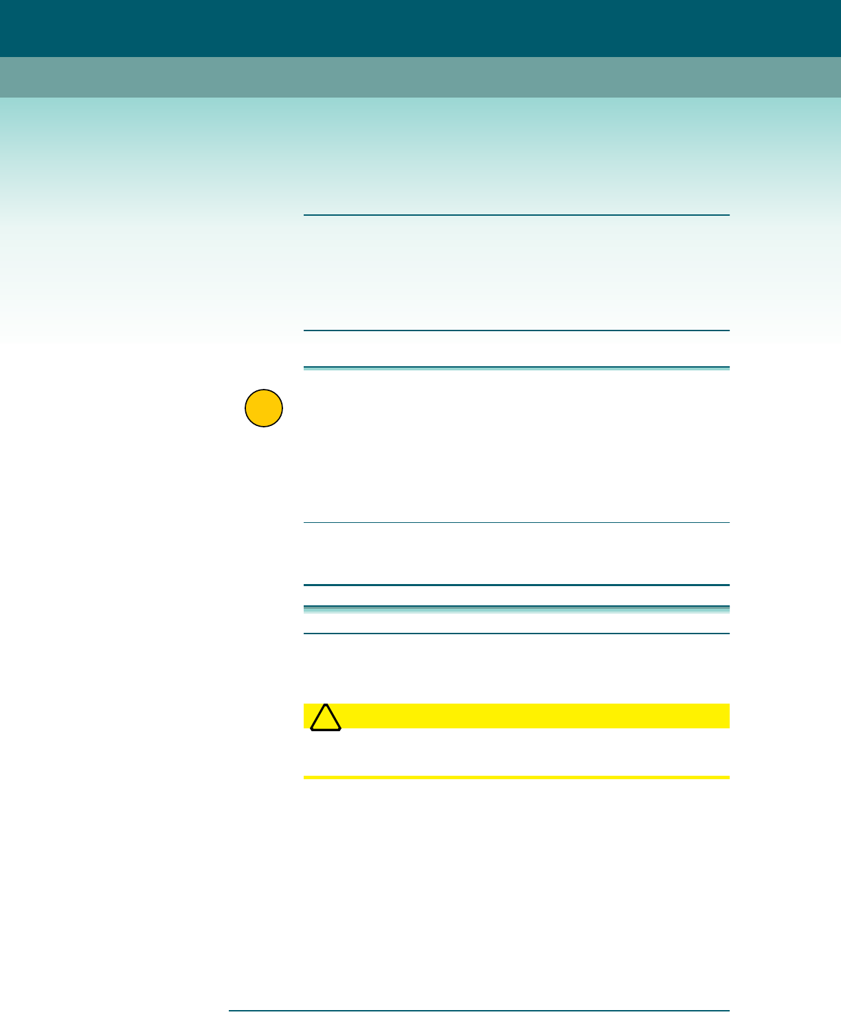
RF Concepts, LLC
Product Release 1 7
DOCNUMBER 9500
Document Issue 1.1
February 2010 Page 7–1
7 Maintaining and Upgrading the Amplifier
7.1 Clean the Chassis 7–1
7.2 Retune the Amplifier 7–2
7.3 Replace the Tube and Fuses 7–2
7.4 Upgrade Firmware 7–3
!
IMPORTANT •The Alpha 9500 is extremely easy to set up, operate, and
maintain. However, failure to carry out each procedure exactly as
described in this manual is likely to lead to amplifier damage,
which is not covered under warranty. Damage to other station
equipment may also result.
•Do not apply oil or grease to any amplifier components. There are
no user-accessible lubrication points in the amplifier.
7.1 Clean the Chassis
Procedure 7-1 Clean the amplifier
Step 1 Power down the amplifier.
Step 2 Disconnect the AC line cord from the power source and lift the cover.
WARNING
!
WARNING! Disconnect the AC line cord from the power source
before lifting the cover for any reason.
Step 3 Clean the interior, particularly high-voltage areas, with a vacuum cleaner
and a soft bristle brush frequently enough to prevent visible accumulation
of dust.
Step 4 Clean the exterior with a mild household liquid detergent. Do not use
chemical solvents, as these may severely damage the front panel or
cabinet finish. Never use an abrasive cleaner.
Step 5 In extremely dusty conditions, secure a thin air filter of the type used for
window air conditioners across the air intake on the rear panel.

Alpha 9500 Linear Amplifier User Manual RF Concepts, LLC
Maintaining and Upgrading the Amplifier Product Release 1
DOCNUMBER 9500
Document Issue 1.1
Page 7–2 February 2010
77
7
Step 6 Replace the cover and reconnect the AC line cord to the power source.
7.2 Retune the Amplifier
Normally you need retune the amplifier only if you change radios,
antennas, or some other aspect of your shack.
When the amplifier is first keyed and RF is sensed, it measures the signal
frequency, moves to the appropriate band and segment, and sets the tune
and load-capacitor positions to the values that you saved for that
frequency. If you saved a different antenna position for that band, it
selects the new position.
Your objective in tuning the amplifier (and the drive applied to it) is to
obtain optimum efficiency and linearity at the desired output power. You
must adjust the amplifier for optimum efficiency and linearity at each
specific power level. If you attempt to operate at higher or lower power
levels than those for which you have adjusted, the following happens:
•At higher power, the amplifier flattops, splatters, and (usually)
produces excessive amplifier grid current.
•At lower power, the amplifier decreases efficiency considerably.
The Alpha 2100 in-line dummy load simplifies this adjustment process by
enabling you to switch between dummy load and antenna at the flip of a
switch.
At the factory, the amplifier is tested and tuned into an Alpha 2100 50-
ohm dummy load and the correct tune and load capacitor values are stored
into the default memory-segment positions. You must retune the
amplifier for your particular station setup and save those settings to the
user memories. After the amplifier has switched to the correct tune and
load settings for that particular frequency, you may touch up the capacitor
settings to achieve maximum output.
For instructions on retuning the amplifier, see Section 5.3, “Tune the
Amplifier,” page 5–7.
7.3 Replace the Tube and Fuses
Step 1 Power down the amplifier.
Step 2 Disconnect the AC line cord from the power source and lift the cover.
WARNING
!
WARNING! Disconnect the AC line cord from the power source
before lifting the cover for any reason.

77
7
DOCNUMBER 9500
Document Issue 1.1
February 2010 Page 7–3
RF Concepts, LLC Alpha 9500 Linear Amplifier User Manual
Product Release 1 Maintaining and Upgrading the Amplifier
!
IMPORTANT The amplifier is equipped with a cover interlock switch that removes
primary power from the amplifier, and a crowbar that short-circuits
high voltage to the chassis when the cover is lifted. These interlocks
protect against electric shock resulting from accidental contact with
the lethal voltages inside the amplifier.
Do not disable the interlock switches for any reason.
Procedure 7-2 Replace the tube and fuses
Step 3 Replace the tube.
Use a single high-quality 8877 tube.
Step 4 Replace fuses.
USE ONLY 20-A, 250-V-RATED FUSES for 190–220 VAC service.
You may use 25-A fuses with caution for line voltages of 90–130 V.
Never replace a fuse with one of a different type or greater current rating.
Blowing of one or both primary line fuses indicates that the maximum
safe average power capability of the amplifier has been substantially
exceeded or that an equipment failure has occurred.
The slow-blow fuse F3, located below the primary line fuses, may prevent
damage to the step-start resistors and HV rectifiers in the event of
abnormal turn-on conditions or HV faults. If the AC interlock is defeated
and primary power is applied while the HV crowbar is closed, the step-
start fuses normally blow.
!
IMPORTANT Damage resulting from use of a fuse of incorrect size or type is not
covered under and may void the warranty.
Step 5 Replace the cover and reconnect the AC line cord to the power source.
7.4 Upgrade Firmware
Occasionally, new firmware for the Alpha 9500 control board becomes
available for download from the Alpha website.
Go to the Alpha website, retrieve the firmware, and store it on your PC.
Then choose one of the following procedures and follow it to install
firmware.
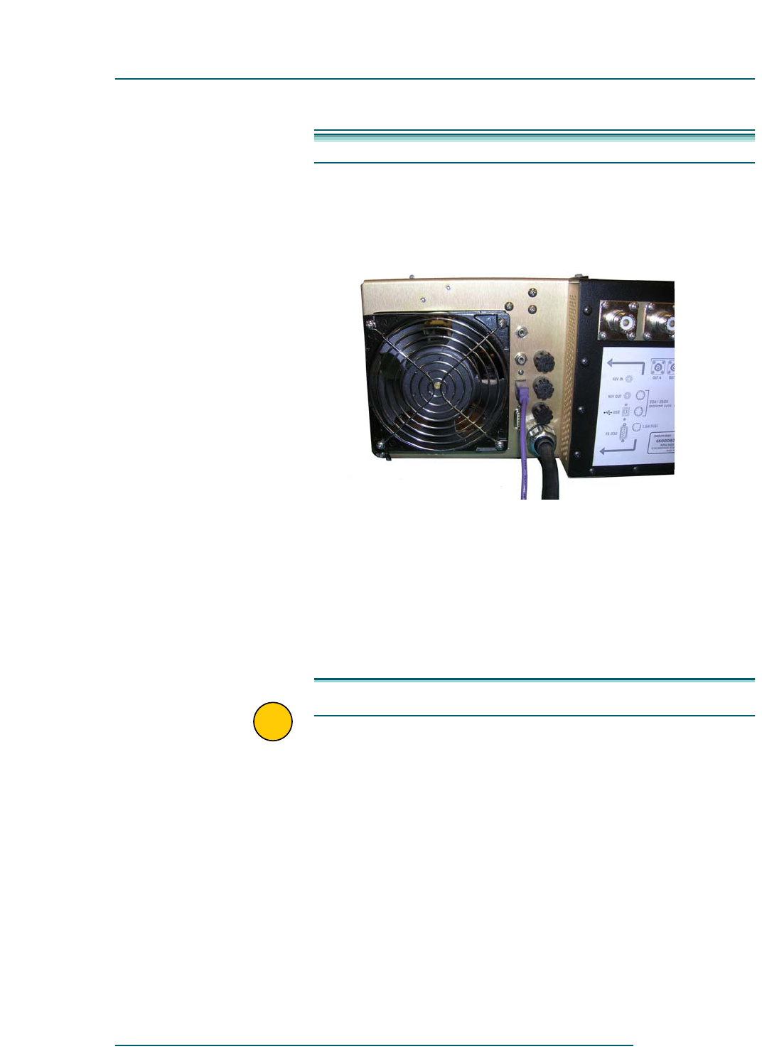
Alpha 9500 Linear Amplifier User Manual RF Concepts, LLC
Maintaining and Upgrading the Amplifier Product Release 1
DOCNUMBER 9500
Document Issue 1.1
Page 7–4 February 2010
77
7
On the Primary Board Procedure 7-3 Upgrade firmware on the primary board
Step 1 With the amplifier plugged into the power supply, turn the amplifier off.
Step 2 Connect a USB cable (Figure 7-1) between the amplifier and the PC.
Figure 7-1 USB cable
If the PC cannot see an additional COM port when the cable is plugged
into the amplifier, run the VCP installer software.
Step 3 On the PC, install the USB driver, if not already done.
The USB driver allocates the amplifier USB connection to a virtual COM
port (VCP), which looks and behaves like any other COM port.
Step 4 On the PC, run the Colt Bootloader and choose the correct COM port and
baud rate.
!
IMPORTANT It is important that you set up the bootloader parameters correctly.

77
7
DOCNUMBER 9500
Document Issue 1.1
February 2010 Page 7–5
RF Concepts, LLC Alpha 9500 Linear Amplifier User Manual
Product Release 1 Maintaining and Upgrading the Amplifier
NOTE: The bootloader menus for setting the COM port and the baud
rate are a little quirky. Although it may look as if there are no other
options from which to choose, there is a little area on the drop-down
menu where you can click to show the other choices. If you have
trouble with this, contact RF Concepts directly.
The bootloader recognizes only COM ports 1 to 9. The amplifier is
normally assigned to COM port 6. Confirm this by going to the PC’s
Device Manager and checking the computer properties.
The correct baud rate is 115,200.
!
IMPORTANT Check only Reload before Program and Reset after Program.
DO NOT check Program data EEPROM, as doing so wipes out all of
your factory calibrations.
Step 5 With the amplifier still turned off, reset the master microprocessor
(hereafter called the processor) by doing the following in quick
succession:
5a On the PC, press F4.
5b On the amplifier, press the FLT button (just below the 7-segment
display on the far right).
The firmware begins to download to the mains controller; a blue progress
bar shows the progress. The process completes in a few minutes.
Step 6 After the download has completed, repeat Step 5 to reset the processor
again.
Resetting the processor twice ensures that the new firmware loads
correctly and takes effect.
Step 7 If the PC cannot see an additional COM port when the USB cable is
plugged into the amplifier, run the VCP installer software.
On the Secondary
Boards There are four secondary boards:
•Display board
•Mains board
•Sound generator board
•Stepper motor board
These boards are shown in the figures below.
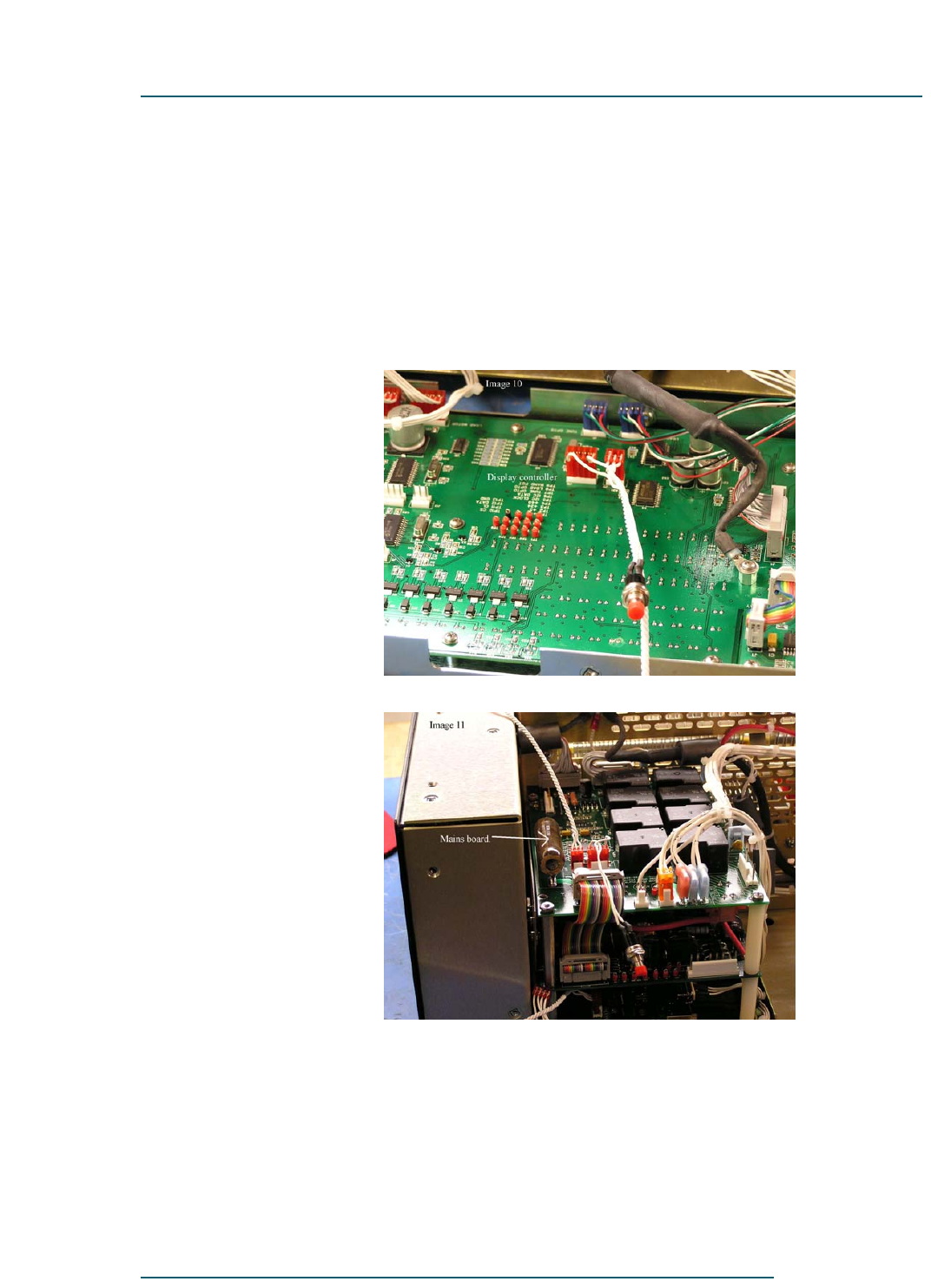
Alpha 9500 Linear Amplifier User Manual RF Concepts, LLC
Maintaining and Upgrading the Amplifier Product Release 1
DOCNUMBER 9500
Document Issue 1.1
Page 7–6 February 2010
77
7
Upgrading the firmware on these boards requires a few more simple steps.
The biggest difference with these upgrades is that you must remove the
cover and front panel to access these boards. In addition, you must install
a special cable between the USB/serial board underneath the power-
supply stack and the processor that is being upgraded. You also need a
processor reset cable. You keep your computer connected to the amplifier
via the USB connector on the back of the amplifier and use the same COM
port as before.
Figure 7-2 Display board
Figure 7-3 Mains board
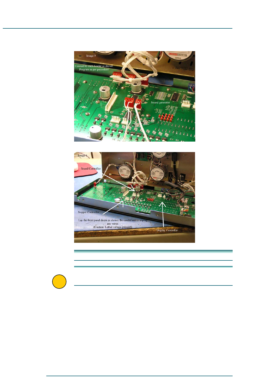
77
7
DOCNUMBER 9500
Document Issue 1.1
February 2010 Page 7–7
RF Concepts, LLC Alpha 9500 Linear Amplifier User Manual
Product Release 1 Maintaining and Upgrading the Amplifier
Figure 7-4 Sound generator board
Figure 7-5 Stepper motor board
Procedure 7-4 Upgrade firmware on the secondary boards
!
IMPORTANT Before you start, review all steps. If you are unsure of any step,
contact RF Concepts.
Step 1 Ensure that the amplifier is connected to the PC via the USB cable.
Step 2 Power down the amplifier.
Step 3 Disconnect the AC line cord from the power source and lift the cover.
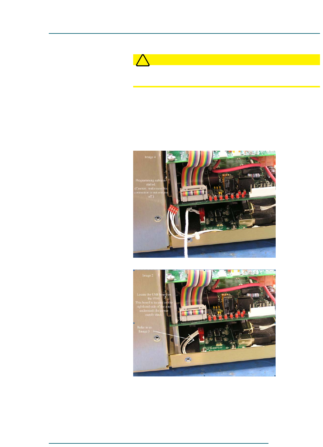
Alpha 9500 Linear Amplifier User Manual RF Concepts, LLC
Maintaining and Upgrading the Amplifier Product Release 1
DOCNUMBER 9500
Document Issue 1.1
Page 7–8 February 2010
77
7
WARNING
!
WARNING! Disconnect the AC line cord from the power source
before lifting the cover for any reason.
Step 4 Remove the transformer and front panel assembly.
Place a towel or a soft cloth in front of the amplifier so as not to scratch
the panel.
Step 5 Connect: the programming cable’s end 1 (Figure 7-6) to the USB/serial
board (Figure 7-7).
Figure 7-6 Programming cable, end 1
Figure 7-7 USB board
Step 6 Connect the programming cable’s end 2 (Figure 7-8) to the 3-pin header
adjacent to the board to be upgraded (Figure 7-9).
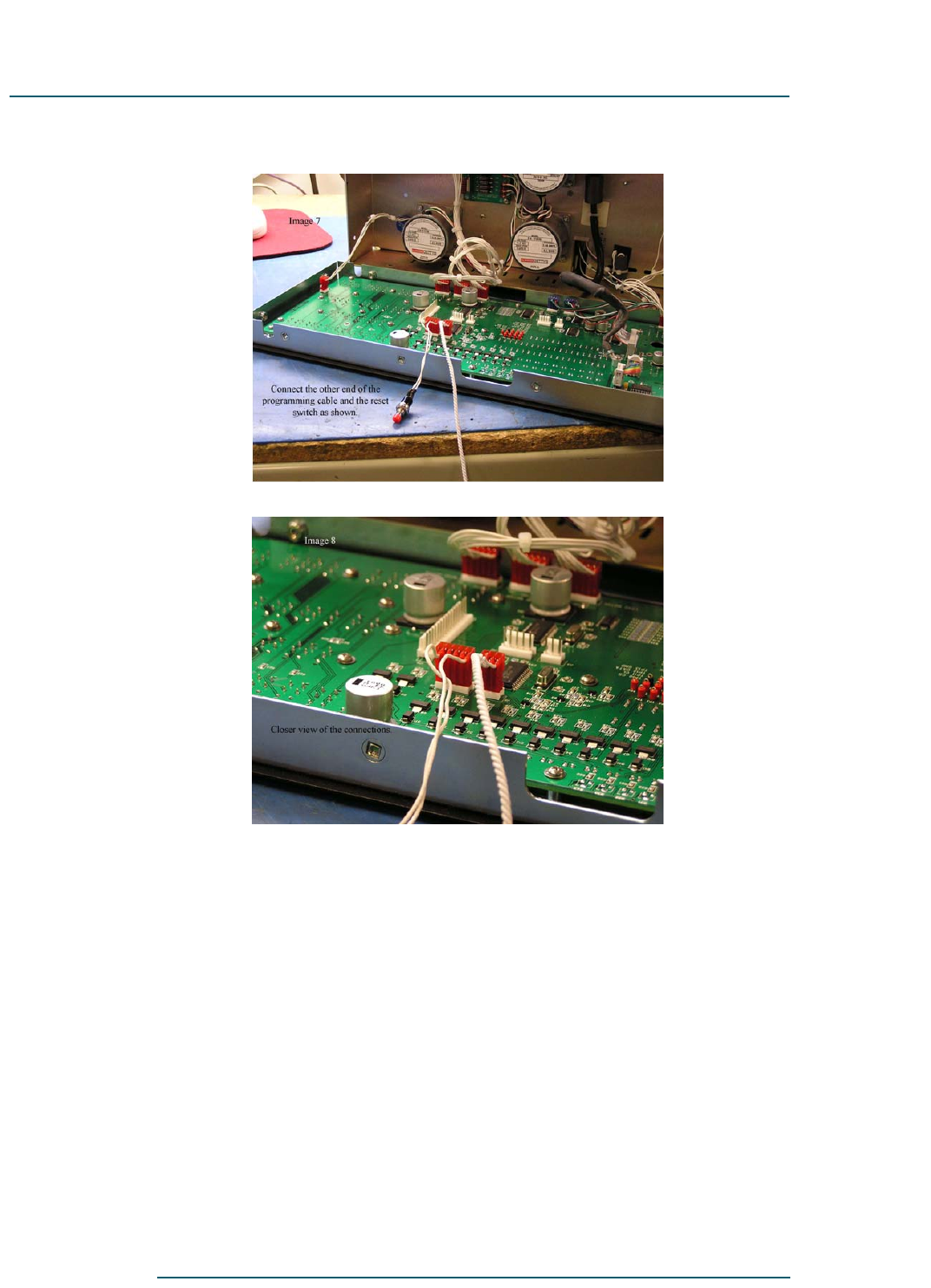
77
7
DOCNUMBER 9500
Document Issue 1.1
February 2010 Page 7–9
RF Concepts, LLC Alpha 9500 Linear Amplifier User Manual
Product Release 1 Maintaining and Upgrading the Amplifier
Figure 7-8 Programming cable, end 2
Figure 7-9 3-pin header
Step 7 Connect the reset-push-button cable to the 5-pin connector.
Step 8 Plug the amplifier in but DO NOT turn it on.
Step 9 Start the Colt Bootloader and select the COM port that was used for the
main-controller upgrade, with the same communications parameters:
•115,200 baud
•No parity
•1 stop bit
•8 data bits
•Flow control = NONE

Alpha 9500 Linear Amplifier User Manual RF Concepts, LLC
Maintaining and Upgrading the Amplifier Product Release 1
DOCNUMBER 9500
Document Issue 1.1
Page 7–10 February 2010
77
7
Step 10 On the bootloader, choose the correct filename for the board to be
upgraded.
Board Filename1
1. x_xx is the current version number.
Display Display_Controller_FP_Vx_xx.HEX
Mains High_Voltage_Mains_Board_Vx_xx.HEX
Sound generator Sound_Generator_FP_Vx_xx.HEX
Stepper motor Stepper_Motor_FP_Vx_xx.HEX
!
IMPORTANT It is critical that you load the correct firmware for each board. Check
often to ensure that you do not put (for example) code for the main
controller onto the mains board.
Step 11 Press F4 to start the load.
Step 12 Press the reset switch on the cable and note the blue progress bar on the
bootloader.
Step 13 When the load is complete:
13a Unplug the amplifier from the wall.
13b Remove the programming cable and reset switch.
13c Replace the front panel, being careful not to crush any wires between
the front panel and the stepper motors.
Step 14 Remove the other end of the programming cable from the USB/serial
board and replace the original connector.
Step 15 Replace the transformer.
Step 16 Replace the cover and reconnect the AC line cord to the power source.

RF Concepts, LLC
Product Release 1 8
DOCNUMBER 9500
Document Issue 1.1
February 2010 Page 8–1
8 Diagnosing Faults
8.1 Overview 8–1
8.2 Fault Codes and Resolutions 8–2
8.1 Overview
One of four situations typically results in a fault:
Table 8-1 Fault situations
Fault description Fault
type
Amplifier action
Incorrect gain (output too low or too
high for the input power supplied)
Soft The OPR switch turns
OFF and the STBY
switch turns ON.
High reflected power (SWR)
Incorrect plate voltage (too high) Hard The amplifier shuts
OFF completely.
RF arc in output circuit including
antenna
If the tube current exceeds about 1.6 A (causing the amplifier to switch to
ON1), diagnose and resolve the fault as described below.
!
IMPORTANT In the event of a fault, the tube biases off, the relays are placed in
bypass mode, and RF from the amplifier goes directly to the antenna.
The FLT (Fault) switch lights and the 7-segment display shows the
number of the last recorded fault.
Do not turn the amplifier off. To clear the fault:
•For a gain fault, wait for the amplifier to reset itself.
•For all other faults, resolve the fault as described in Section 8.2,
“Fault Codes and Resolutions.” Then press the left ON button to
release the fault and press the OPER button to continue.

Alpha 9500 Linear Amplifier User Manual RF Concepts, LLC
Diagnosing Faults Product Release 1
DOCNUMBER 9500
Document Issue 1.1
Page 8–2 February 2010
88
8
8.2 Fault Codes and Resolutions
Fault numbers and descriptions are as follows:
Table 8-2 Fault code summary
Number Description
1 Gain fault
2 Tap not found
3 Soft Ip trip
4 Hard Ip trip
5 Vp under voltage
6 Output relay closure fail
7 Output relay may be stuck
8 Bandswitch set failure
9 Tune cap zero failure
10 Load cap zero failure
11 Over-temperature
12 Reflected power too high
13 Clear over-temperature
14 Plate voltage too high
15 Grid current too high
16 Autotune failure
17 Plate current too high with amplifier unkeyed
18 Input power too high
19 Unauthorized frequency
Fault code 1
Description Gain fault.
Explanation The power gain (power output divided by power input) of the amplifier
has fallen below a value of 10 (10 dB). The normal gain of the amplifier
when properly tuned is around 30 (15 dB), so this represents a substantial
drop in gain. It is, in fact, the first line of protection for the unit, since
almost any major problem in the amplifier (or even in the load connected
to the amplifier) manifests as a drop in gain.

88
8
DOCNUMBER 9500
Document Issue 1.1
February 2010 Page 8–3
RF Concepts, LLC Alpha 9500 Linear Amplifier User Manual
Product Release 1 Diagnosing Faults
The amplifier attempts to automatically clear this fault after 4 seconds
and, if the key line is still asserted, go into OPERATE mode. If the fault
reoccurs, this process repeats indefinitely. If it occurs often in a short
period of time, it is important that you determine the underlying cause and
correct the problem.
If you operate the amplifier remotely, the control software should be
capable of taking the necessary steps over the USB or RS232 interface to
“safe” the amplifier. Although no maximum number of attempts to get
back online are specified, it is possible, if this fault occurs repeatedly, that
consequential damage to the amplifier may result. Such damage may not
be covered under warranty.
As noted previously, this fault (and several others) are inhibited (disabled)
if the drive power from the exciter into the amplifier is less than 20 W.
The amplifier is generally safe at this drive power level, and it provides a
window for you to exercise the various controls to either get the amplifier
tuned to within the nominal gain range or determine the underlying cause
of the problem.
Resolution 1. Ensure that the load is good under low power. Put the amplifier in
bypass mode, and note the standing wave ratio (swr) reported by the
exciter. If it is very high, check the antenna/load.
2. If you have recently switched to a new exciter, ensure that it is not
putting out excessive power. It has been found that even new
transceivers from reputable suppliers develop problems that cause
them to put out power much higher than expected, either transiently
or continuously. High input power can cause the amplifier to saturate,
and the reported gain to drop. Drive powers above 100 W can damage
the amplifier and cause this fault. Within-range drive powers at the
wrong frequency can also cause this fault.
3. Ensure that the plate voltage (Vp on the digital meter) is within limits
(3.0 to 3.8 kV).
•At the low end of this range, the amplifier struggles to meet the
gain specification. It is possible that the mains board has set an
inappropriate tap on the primary of the transformer. This can
happen for several reasons, but a procedure has been
implemented that enables you to override the automatic tap
selection feature and force the amplifier to set any desired
primary taps. For information on how to force tap selection,
contact RF Concepts technical support.
•At the high end of this range, it is also possible that an incorrect
tap has been set, although this normally causes a different fault
code.

Alpha 9500 Linear Amplifier User Manual RF Concepts, LLC
Diagnosing Faults Product Release 1
DOCNUMBER 9500
Document Issue 1.1
Page 8–4 February 2010
88
8
Fault code 2
Description Tap not found.
Explanation The mains board has measured a line voltage that does not correspond to
an acceptable primary tap setting.
The mains board has a set of relays that can select an appropriate
combination of primary windings for the power transformer. The tap can
be selected either automatically based on the mains board estimate of line
voltage, or by force when you tell the amplifier which tap to use.
To ease initial installation of the amplifier, it is shipped with automatic tap
selection enabled. This is appropriate for most situations, but it is possible
that a particular situation may fake the voltage estimation circuitry out,
and cause the amplifier to select an inappropriate tap. This can result in
off-nominal conditions for the plate and heater voltages.
The reasons for this fault are several. It is likely that either the AC supply
is floating (has a poorly defined ground reference) or the waveform is
significantly distorted (by spikes or other irregularities).
It is possible to operate the amplifier with some of these less-than-perfect
power sources by enabling the force-tap-selection option. For information
on how to force tap selection, contact RF Concepts technical support.
Resolution 1. Measure the line voltage using an accurate voltmeter. Compare this
value with the reported value in the amplifier telemetry stream. This
is most easily done by running the Alpha Remote/AR9500 PC
application. The line voltage is reported in the rectangle around the
meter selection buttons. If necessary, this can be done with the
amplifier plugged in but in the OFF condition.
2. If the reported and measured values differ by more than a few volts,
investigate the cause. Possible reasons are:
•Poor AC voltage waveform (check with an oscilloscope)
•Poor ground (check from chassis to Line A and Line B)
If neither of these cases seem to exist, it is possible that the
measurement circuitry on the mains board has drifted. If this is the
case, contact RF Concepts technical support.
3. Assuming the value is being reported correctly, compare this value to
the values in the following table. There are 5 possible primary tap
selections, with values as indicated.
Tap number Min voltage Max voltage
1 89.9 109.9
2 110.0 135.0

88
8
DOCNUMBER 9500
Document Issue 1.1
February 2010 Page 8–5
RF Concepts, LLC Alpha 9500 Linear Amplifier User Manual
Product Release 1 Diagnosing Faults
The amplifier selects the tap appropriate to the range reported as
being measured. If the measured value does not fall into one of the 5
ranges, the amplifier does not turn on unless you activate manual tap
selection.
Fault code 3
Description Soft Ip trip.
Explanation The current in the high voltage (HV) circuit is greater than 1.6 A.
Normal plate current for the amplifier at 1.5 kW output power is in the
range 0.8 to 1.1 A. Above this value, the tube may be at or above its rated
plate dissipation. This trip is set so that, if the plate current exceeds 1.6 A
for a short time, it trips and goes into bypass mode. You should
investigate the cause and resolve the problem to avoid damage to the
amplifier.
Resolution •Ensure that the drive power to the amplifier is not too high. This could
be because of a problem at the exciter. Put the amplifier in bypass
mode and transmit with the exciter. The power should normally be 65
W or less, normally more like 50 W. It is even possible that the exciter
has a problem that is causing it to put out brief high power spikes. It
is possible that the exciter and amplifier are interacting to produce
this effect.
Fault code 4
Description Hard Ip trip.
Explanation The amplifier has tripped completely off, and you have turned it on again
to either of the ON positions. The HV circuit current exceeds about 2.5 A.
The mains board contains a latching relay and associated circuitry that
trips when the current reaches that level.
Under most circumstances, the mains board reports a fault 3 (soft Ip)
when the plate current exceeds 1.6 A. If this software fault does not
happen, a hardware circuit kicks in and essentially unplugs the amplifier.
This is normally caused by a direct arc from the HV circuit to ground,
inside the tube or elsewhere.
Resolution •Reduce the drive power or retune the amplifier.
3 189.9 209.9
4 210.0 229.9
5 230.0 265.0
Tap number Min voltage Max voltage

Alpha 9500 Linear Amplifier User Manual RF Concepts, LLC
Diagnosing Faults Product Release 1
DOCNUMBER 9500
Document Issue 1.1
Page 8–6 February 2010
88
8
Fault code 5
Description Vp under voltage.
Explanation The mains board monitors the plate voltage (HV, Vp) for approximately
2 seconds after the amplifier is turned fully on (ON 2).
If Vp fails to reach approximately 2.8 kV during this time, the mains
board reports this fault code.
Resolution 1. Ensure that the mains board is selecting the correct primary
transformer tap. See fault code 2 for information on how to do this.
2. If the correct primary tap is being selected, then the problem is
elsewhere. Unplug the amplifier, remove the top cover, and inspect
the mains board and high voltage board. Unplug each of the
transformer connectors and inspect them for problems.
Fault code 6
Description Output relay closure fail.
Explanation The master controller monitors the state of the output relay using an
auxiliary DC bias applied through a pair of RF chokes. This allows it to
determine that the output relay has traveled to the closed condition, and
that it is safe to bias the tube to OPERATE mode.
Resolution •Call RF Concepts at 303-473-9232.
Fault code 7
Description Output relay may be stuck.
Explanation If the output relay appears to be closed when the amplifier is keyed up, it
is possible that the output relay is stuck in the ÖN condition for one of
several reasons. See Fault code 6 for more information.
Resolution •None. You should not see this fault in the field.
Fault code 8
Description Bandswitch set failure.
Explanation The stepper motor controller processor is unable to land the apparent
bandswitch position on the correct setting within the precision required.
Resolution 1. Turn the amplifier off and back on.

88
8
DOCNUMBER 9500
Document Issue 1.1
February 2010 Page 8–7
RF Concepts, LLC Alpha 9500 Linear Amplifier User Manual
Product Release 1 Diagnosing Faults
2. If the fault does not clear, turn the amplifier off, unplug it from the
AC mains., plug it back in, and power it up again.
3. If the fault still does not clear, with the amplifier on, press a
bandswitch on the front of the amplifier.
Fault code 9
Description Tune cap zero failure.
Explanation The stepper motor controller is unable to determine the zero position for
the tune capacitor.
The tune capacitor has an opto-interrupter that is actuated by a small vane
on the drive shaft. When the amplifier is turned to the ON2 or ON/AMP
position, the stepper controller attempts to move the vane until it just
occludes the opto-interrupter. This position is registered as a 0 (zero) for
the tune capacitor, and represents the minimum attainable capacitance for
that capacitor. Maximum capacitance is attained when the stepper motor
controlling the tune capacitor has taken 100 steps. The stepper motor
controller counts how many steps it takes, adding when the capacitance
increases and subtracting when the capacitor decreases. The count
(between 0 and 100) is the tune capacitor position. When the master
controller (MC) sends a command indicating that a new tune capacitor
position is desired, the stepper motor controller knows in which direction
and for how many steps to turn the capacitor.
Resolution 1. Unplug the amplifier, wait 30 seconds, and plug it back ON to the
ON2 or ON/AMP setting.
2. Even if the last fault is still fault 9, attempt to turn the tune capacitor
from the buttons on the front panel or from the AR9500 PC
application. If the capacitor responds, the fault may have cleared.
3. If the fault persists, contact RF Concepts technical support. If
possible, send them the contents of the fault log. To display the fault
log, from the AR9500 PC application, open the Fault window and
select Tools > Get fault log.
Fault code 10
Description Load cap zero failure.
Explanation The stepper motor controller is unable to determine the zero position for
the load capacitor.
The load capacitor has an opto-interrrupter that is actuated by a small vane
on the drive shaft. When the amplifier is turned to the ON2 or ON/AMP
position, the stepper controller attempts to move the vane until it just

Alpha 9500 Linear Amplifier User Manual RF Concepts, LLC
Diagnosing Faults Product Release 1
DOCNUMBER 9500
Document Issue 1.1
Page 8–8 February 2010
88
8
occludes the opto-interrupter. This position is registered as a 0 (zero) for
the load capacitor, and represents the minimum attainable capacitance for
that capacitor. Maximum capacitance is attained when the stepper motor
controlling the load capacitor has taken 100 steps. The stepper motor
controller counts how many steps it takes, adding when the capacitance
increases and subtracting when the capacitor decreases. The count
(between 0 and 100) is the load capacitor position. When the master
controller (MC) sends a command indicating that a new load capacitor
position is desired, the stepper motor controller knows in which direction
and for how many steps to turn the capacitor.
Resolution 1. Unplug the amplifier, wait 30 seconds, and plug it back ON to the
ON2 or ON/AMP setting.
2. Even if the last fault is still fault 10, attempt to turn the load capacitor
from the buttons on the front panel or from the AR9500 PC
application. If the capacitor responds, the fault may have cleared.
3. If the fault persists, contact RF Concepts technical support. If
possible, send them the contents of the fault log. To display the fault
log, from the AR9500 PC application, open the Fault window and
select Tools > Get fault log.
Fault code 11
Description Over-temperature.
Explanation The amplifier has a built-in temperature sensor to ensure that the tube
does not overheat. The sensor is located on the cathode board, in the tube
deck compartment. Air from the blower motor impinges on this board and
then flows up through the tube anode fins. Normally the temperature it
reports is at approximately this air temperature. Since the air has already
been drawn over other parts of the amplifier, it is some 10–20C warmer
than ambient air. The trip value is currently set to 50C.
The amplifier goes to ON AMP, but in bypass mode and with the tube
biased off. This should reduce plate dissipation to a minimum and, if the
air system is working correctly, the temperature should start to fall. When
it reaches a safe value, the amplifier can be put in service again, as
indicated by fault code 13 (clear temperature).
Resolution 1. Ensure that there is air exiting the amplifier from the hexagonal
pattern of holes near the rear left. If not, this is likely the cause.
2. If there is no air leaving the amplifier when it is in the ON AMP
position, assuming that all other front panel displays appear normal,
ensure that there is nothing obstructing the air flow at the inlet (on the
right rear of the amplifier) or at the exit.

88
8
DOCNUMBER 9500
Document Issue 1.1
February 2010 Page 8–9
RF Concepts, LLC Alpha 9500 Linear Amplifier User Manual
Product Release 1 Diagnosing Faults
3. Ensure that the external fan is operating. The fan is at the right rear of
the amplifier, covered by a wire grill. It should start to rotate in the
ON AMP condition. Use a flashlight if necessary to avoid the
appearance of nonrotation due to the stroboscopic effect. This can be
done without removing the amplifier cover.
4. Check the internal airways of the amplifier. Unplug the amplifier,
remove the cover, and ensure that the blower motor (to the right of the
tube) is clean and that its impeller rotates when moved gently with a
long screwdriver. Look down into the tube and ensure that the
passages between the anode fins are not blocked, for example by an
accumulation of dust.
5. Ensure that amplifier is being operated with a tuning condition that
does not result in poor efficiency.
6. Ensure that the tube standing bias (keyed, with no RF) is not greater
than 500 mA. Key the amplifier with the meter set to Ip to make this
measurement. If Ip is greater than 500 mA, then there may be a
problem in the cathode bias circuitry, on the cathode board, or in the
tube itself.
Fault code 12
Description Reflected power too high.
Explanation The amplifier monitors the apparent reflected power at its output. If the
power is above the set value, currently 375 W, the amplifier goes into
BYPASS mode and attempts to clear the fault.
Resolution •Ensure that antennas and other equipment installed after the amplifier
were installed correctly.
Fault code 13
Description Clear over-temperature.
Explanation The amplifier has recovered from fault 11 (temperature fault).
Resolution •See fault 11.
Fault code 14
Description Plate voltage too high.
Explanation The plate voltage has exceeded a safe value, currently 3800 Vdc.
Resolution 1. Ensure that the AC mains voltage is correct.

Alpha 9500 Linear Amplifier User Manual RF Concepts, LLC
Diagnosing Faults Product Release 1
DOCNUMBER 9500
Document Issue 1.1
Page 8–10 February 2010
88
8
2. Unplug the amplifier, plug it back in, wait for at least 30 seconds, then
turn it back on.
Fault code 15
Description Grid current too high.
Explanation The amplifier monitors the grid current and, if it exceeds a safe value for
a period of time, it goes into BYPASS mode and reports this fault. The
usual cause is too much drive for the current output loading condition. It
may represent amplifier overdrive (excessive input power) or incorrect
tune and load capacitor settings.
Resolution •Reduce the drive or retune.
Fault code 16
Description Autotune failure.
Explanation The autotune algorithm has encountered a problem that causes it to go
through a large number of iterations without being able to find an
acceptable tune condition, and has been stopped.
Resolution •Reduce the drive and restart the autotune.
Fault code 17
Description Plate current too high with amplifier unkeyed.
Explanation When the amplifier is unkeyed, the plate current should be quite low.
Some failure conditions can cause the plate current to exceed a safe level
and produce this fault code.
Resolution 1. If the tube is shorted out, replace it.
2. Ensure that the HV circuit is functioning properly.
Fault code 18
Description Input power too high.
Explanation The input drive power from the exciter is greater than a preset threshold,
currently 100 W.
Resolution •Reduce the input power to within proper limits.

88
8
DOCNUMBER 9500
Document Issue 1.1
February 2010 Page 8–11
RF Concepts, LLC Alpha 9500 Linear Amplifier User Manual
Product Release 1 Diagnosing Faults
Fault code 19
Description Unauthorized frequency.
Explanation The amplifier is not authorized to transmit on that frequency. Amateur
equipment sold in the United States is not authorized to transmit between
26 and 28 MHz.
Resolution •Change the frequency.

Alpha 9500 Linear Amplifier User Manual RF Concepts, LLC
Diagnosing Faults Product Release 1
DOCNUMBER 9500
Document Issue 1.1
Page 8–12 February 2010
88
8

RF Concepts, LLC
Product Release 1
DOCNUMBER 9500
Document Issue 1.1
February 2010 Page Term–1
Terminology
Terminology
NOTE: For detailed explanations of the following terms, see various publications including the latest
American Radio Relay League (ARRL) Handbook.
A
AC — Alternating current. Electric current whose
magnitude and direction vary with time.
ALC — Automatic Level Control. Technology
that automatically controls output power.
ampere — Unit of electric current.
ARRL — American Radio Relay League. US
national organization of amateur radio
operators. For more information, go to
www.arrl.org.
AWG — American wire gauge. Standard method
of denoting wire diameter.
B
B1 — Modulation class AB1. Amplifier-circuit
class that provides good linearity in push-pull
configuration.
C
CW — Continuous wave. Electromagnetic wave
of constant amplitude and frequency.
D
dB — Decibel. Logarithmic unit of measure of the
power of sound relative to a reference level.
E
exciter — Radio that provides RF drive for the
Alpha 9500 to operate. The transmitter portion
of the transceiver.

Alpha 9500 Linear Amplifier User Manual RF Concepts, LLC
Page Terminology Product Release 1
DOCNUMBER 9500
Document Issue 1.1
Page Term–2 February 2010
F
FCC — Federal Communications Commission.
For more information, go to www.fcc.gov.
FM — Frequency modulation. Modulation scheme
in which information is conveyed over a carrier
wave by variations in frequency.
FSK — Frequency-shift keying. Type of
frequency modulation in which information is
conveyed by shifts in the output frequency
between predetermined values.
H
HF — High frequency. Radio frequency within the
range 3–30 MHz.
HV — High voltage. Electrical circuit in which the
voltage used presents risk of both electric shock
and electrical arcing.
Hz — Hertz. One periodic event per second.
I
Ip — Idling plate current. Plate current measured
when the amplifier is keyed and RF is not
present.
K
key — Signal from the radio to the amplifier that
instructs the amplifier to switch from receive to
transmit mode because the radio is ready to
generate RF power. The (programmable) delay
between keydown and RF out is generally 8–12
ms. When the amplifier is keyed, it is in State 5.
kV — Kilovolt. 1000 V.
kVA — Kilovolt-ampere. 1000-W capability.
kVA * 0.8 = kilowatts.
kW — Kilowatt. 1000 W.
L
LED — Light-emitting diode. Semiconductor
diode that emits incoherent narrow-spectrum
light, providing a form of electroluminescence.
LV — Low voltage. Electrical circuit in which the
voltage used presents risk of electric shock but
only minor risk of electrical arcing.

DOCNUMBER 9500
Document Issue 1.1
February 2010 Page Term–3
RF Concepts, LLC Alpha 9500 Linear Amplifier User Manual
Product Release 1 Terminology
M
mA — Milliampere. 10-6 A. MHz — Megahertz. 106 Hz.
O
OPR — Operate. PCB — Printed circuit board. Board that
mechanically supports and electrically connects
electronic components.
P
PSK — Phase-shift keying. Digital modulation
scheme in which information is conveyed by
changes, or modulations, in the phase of a
reference signal.
Q
QSK — Quadrature-shift keying. Digital
modulation scheme in which the transmitter is
on only for the duration of each dot or dash and
switches to receive between each dot or dash,
allowing the operator to hear any signal being
sent.
R
RCA — Radio Corporation of America. Also a
type of interconnecting plug.
RF — Radio frequency. Frequency within the
range 3 Hz–300 GHz.
RG-x/x — Coaxial cable type.
RMS — Root mean square. Statistical measure of
the magnitude of a varying quantity such as a
wave.
RTTY — Radioteletype. Telecommunications
system consisting of two or more teleprinters
using radio as the transmission medium.
S
SSB — Single-sideband. Modulation scheme that
refines upon amplitude modulation.
SSTV — Slow-scan television. Picture-
transmission method for transmitting and
receiving static pictures via radio.
STBY — Standby. Mode in which an electronic
appliance is turned off but under power and
ready to activate on command.
SWR — Standing-wave ratio. Ratio of the
amplitude of a partial standing wave at an
antinode (maximum) to the amplitude at an

Alpha 9500 Linear Amplifier User Manual RF Concepts, LLC
Page Terminology Product Release 1
DOCNUMBER 9500
Document Issue 1.1
Page Term–4 February 2010
adjacent node (minimum). Measure of antenna
and feedline efficiency.
T
T/R — Transmit /receive. transceiver — Device that has both a transmitter
and a receiver within the same circuitry or
chassis.
U
UHF — Ultra-high frequency. Radio frequency
within the range 300–3000 MHz (3 GHz).
US — United States.
V
VAC — Volts of alternating current.
VDC — Volts of direct current.
VSWR — Voltage standing-wave ratio. Example:
If voltage SWR = 1.2:1, the maximum
standing-wave amplitude is 1.2 times greater
than the minimum standing-wave amplitude.

RF Concepts, LLC
Product Release 1
DOCNUMBER 9500
Document Issue 1.1
February 2010 Page Schem–1
Schematics
Schematics
NOTE: The following pages contain detailed schematics for the Alpha 9500 linear amplifier.

Alpha 9500 Linear Amplifier User Manual RF Concepts, LLC
Page Schematics Product Release 1
DOCNUMBER 9500
Document Issue 1.1
Page Schem–2 February 2010