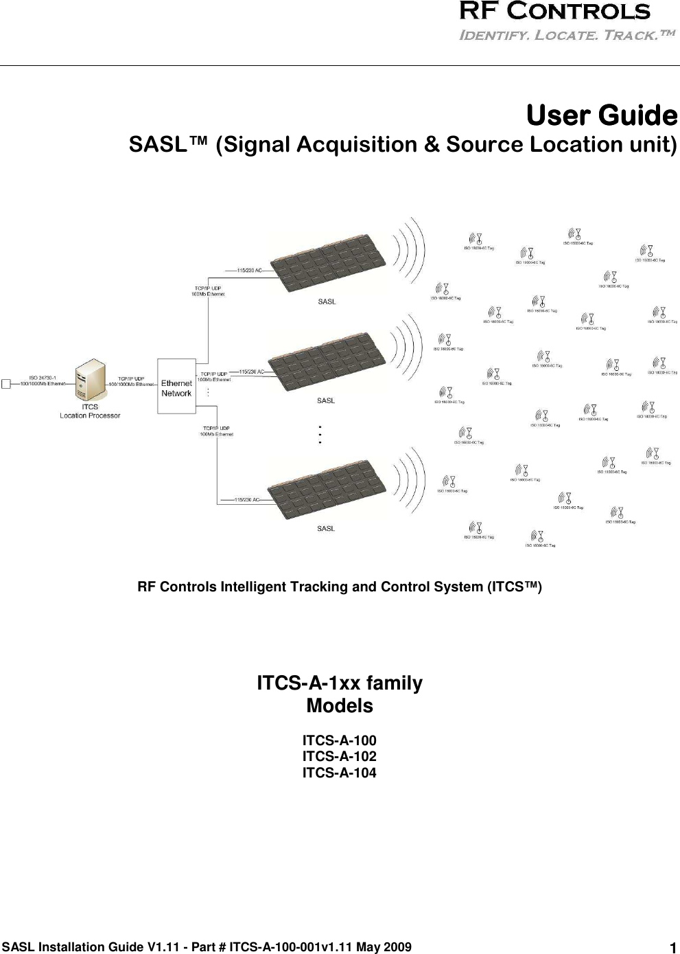
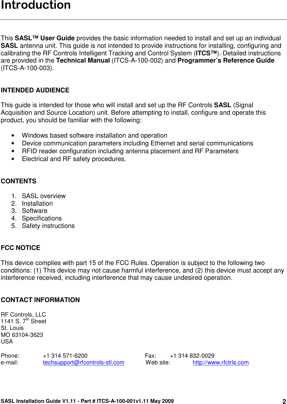
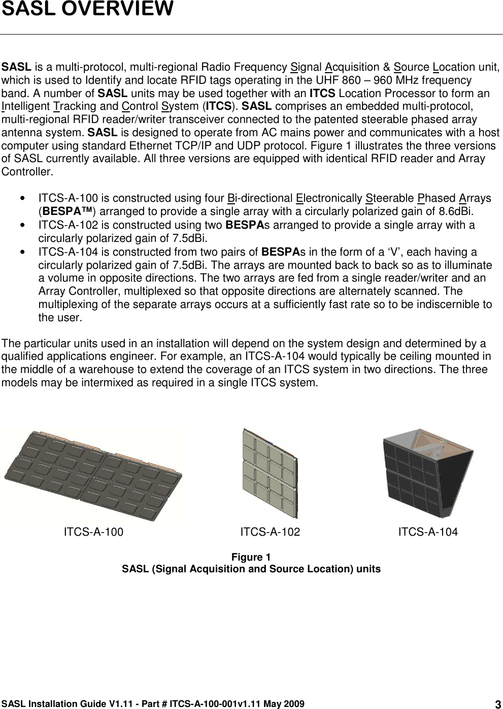
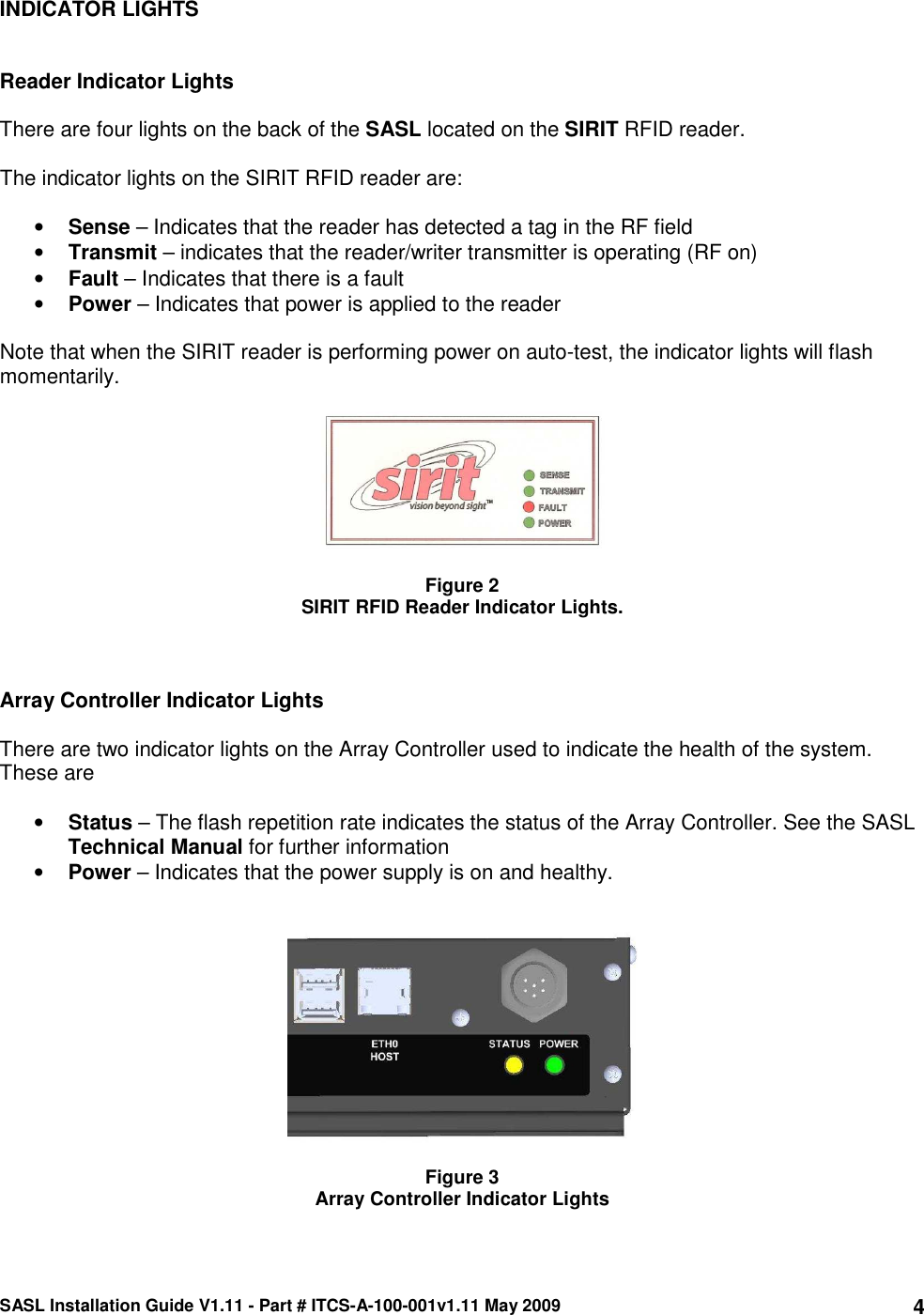
RF Controls ITCSA104 RF ID Signal Acquisition & Source Location unit ITCS104 User Manual SASL Installation Guide v1 11 final

RF Controls, LLC RF ID Signal Acquisition & Source Location unit ITCS104 SASL Installation Guide v1 11 final

Contents

User Manual 2

SASL Installation Guide V1.11 - Part # ITCS-A-100-001v1.11 May 2009 1      User GuideUser GuideUser GuideUser Guide  SASL™ (Signal Acquisition & Source Location unit)       RF Controls Intelligent Tracking and Control System (ITCS™)     ITCS-A-1xx family  Models  ITCS-A-100 ITCS-A-102 ITCS-A-104
SASL Installation Guide V1.11 - Part # ITCS-A-100-001v1.11 May 2009 2Introduction    This SASL™ User Guide provides the basic information needed to install and set up an individual SASL antenna unit. This guide is not intended to provide instructions for installing, configuring and calibrating the RF Controls Intelligent Tracking and Control System (ITCS™). Detailed instructions are provided in the Technical Manual (ITCS-A-100-002) and Programmer’s Reference Guide (ITCS-A-100-003).    INTENDED AUDIENCE  This guide is intended for those who will install and set up the RF Controls SASL (Signal Acquisition and Source Location) unit. Before attempting to install, configure and operate this product, you should be familiar with the following:  •  Windows based software installation and operation •  Device communication parameters including Ethernet and serial communications •  RFID reader configuration including antenna placement and RF Parameters •  Electrical and RF safety procedures.   CONTENTS   1.  SASL overview 2.  Installation 3.  Software  4.  Specifications 5.  Safety instructions   FCC NOTICE  This device complies with part 15 of the FCC Rules. Operation is subject to the following two conditions: (1) This device may not cause harmful interference, and (2) this device must accept any interference received, including interference that may cause undesired operation.   CONTACT INFORMATION  RF Controls, LLC 1141 S. 7th Street St. Louis MO 63104-3623 USA  Phone:    +1 314 571-6200                                   Fax:      +1 314 832-0029 e-mail:    techsupport@rfcontrols-stl.com             Web site:   http://www.rfctrls.com
SASL Installation Guide V1.11 - Part # ITCS-A-100-001v1.11 May 2009 3SASL OVERVIEW    SASL is a multi-protocol, multi-regional Radio Frequency Signal Acquisition & Source Location unit, which is used to Identify and locate RFID tags operating in the UHF 860 – 960 MHz frequency band. A number of SASL units may be used together with an ITCS Location Processor to form an Intelligent Tracking and Control System (ITCS). SASL comprises an embedded multi-protocol, multi-regional RFID reader/writer transceiver connected to the patented steerable phased array antenna system. SASL is designed to operate from AC mains power and communicates with a host computer using standard Ethernet TCP/IP and UDP protocol. Figure 1 illustrates the three versions of SASL currently available. All three versions are equipped with identical RFID reader and Array Controller.  •  ITCS-A-100 is constructed using four Bi-directional Electronically Steerable Phased Arrays (BESPA™) arranged to provide a single array with a circularly polarized gain of 8.6dBi.  •  ITCS-A-102 is constructed using two BESPAs arranged to provide a single array with a circularly polarized gain of 7.5dBi.  •  ITCS-A-104 is constructed from two pairs of BESPAs in the form of a ‘V’, each having a circularly polarized gain of 7.5dBi. The arrays are mounted back to back so as to illuminate a volume in opposite directions. The two arrays are fed from a single reader/writer and an Array Controller, multiplexed so that opposite directions are alternately scanned. The multiplexing of the separate arrays occurs at a sufficiently fast rate so to be indiscernible to the user.  The particular units used in an installation will depend on the system design and determined by a qualified applications engineer. For example, an ITCS-A-104 would typically be ceiling mounted in the middle of a warehouse to extend the coverage of an ITCS system in two directions. The three models may be intermixed as required in a single ITCS system.         ITCS-A-100  ITCS-A-102  ITCS-A-104  Figure 1 SASL (Signal Acquisition and Source Location) units
SASL Installation Guide V1.11 - Part # ITCS-A-100-001v1.11 May 2009 4INDICATOR LIGHTS   Reader Indicator Lights  There are four lights on the back of the SASL located on the SIRIT RFID reader.  The indicator lights on the SIRIT RFID reader are:  • Sense – Indicates that the reader has detected a tag in the RF field • Transmit – indicates that the reader/writer transmitter is operating (RF on) • Fault – Indicates that there is a fault • Power – Indicates that power is applied to the reader  Note that when the SIRIT reader is performing power on auto-test, the indicator lights will flash momentarily.    Figure 2 SIRIT RFID Reader Indicator Lights.    Array Controller Indicator Lights  There are two indicator lights on the Array Controller used to indicate the health of the system. These are  • Status – The flash repetition rate indicates the status of the Array Controller. See the SASL Technical Manual for further information • Power – Indicates that the power supply is on and healthy.     Figure 3 Array Controller Indicator Lights
SASL Installation Guide V1.11 - Part # ITCS-A-100-001v1.11 May 2009 5Installation    MECHANICAL INSTALLATION  Each model of the ITCS-A-1xx family of SASL units is mounted slightly differently.  SASL units weigh up to 85 lbs (38.5kg), so it is important to ensure that the structure, to which the SASL is to be attached, is of sufficient strength.  The SASL may be ceiling mounted, wall mounted or attached to a suitable stand. When ceiling mounted, a safety cable must be secured to a separate ceiling fixture and attached to the SASL mounting bracket.  When mounting the SASL as a stand-alone unit, make sure that it is mounted the correct way up as indicated by information in the Technical Manual, for the specific SASL.  If the SASL is one of several and is part of an ITCS network, then orient each SASL according to the ITCS system installation drawings. If in doubt contact a member of our technical support team.  ITCS-A-100 The ITCS-A-100 SASL is provided in its standard configuration with a mounting bracket for installation in a landscape orientation. An optional portrait mounting bracket is available if under special circumstances an installation configuration requires the SASL to be installed in portrait orientation. When mounting the SASL, the SIRIT RFID reader should be below the mounting tube as shown in figure 5, to ensure that the center of gravity is below the axis of the mounting tube.  Consult the Technical Manual, for further information.  Contact a member of our technical support team for more information.    ITCS-A-102 The ITCS-A-102 SASL is only mounted in a landscape orientation because the array is symmetrical there is no benefit to mounting the array in a portrait fashion.  When mounting the SASL, the SIRIT RFID reader should be below the mounting tube as shown in figure 6, to ensure that the center of gravity is below the axis of the mounting tube.  Consult the Technical Manual, for further information.  Contact a member of our technical support team for more information.    ITCS-A-104 The ITCS-A-104 SASL is designed to be mounted by hanging the array from above as shown in figure 1.  The SASL must be stabilized to ensure that the unit does not move once mounted.  Consult the Technical Manual, for further information.  Contact a member of our technical support team for more information.    The SASL mounting bracket incorporates a mounting tube which is designed to be attached to industry standard “UNISTRUT®” industrial framing systems. (See: www.unistrut.com for more information). Figure 4 shows the ITCS-A-100 and ITCS-A-102 mounting brackets. The ITCS-A-104 mounting is similar and uses the same “UNISTRUT” hardware.  When mounting the SASL as a stand-alone unit, make sure that it is mounted the correct way up as indicated by information in the Technical Manual, for the specific SASL. If the SASL is one of several and is part of an ITCS network, then orientate each SASL according to the ITCS system installation drawings. If in doubt contact a member of our technical support team.
SASL Installation Guide V1.11 - Part # ITCS-A-100-001v1.11 May 2009 6 ITCS-A-100 Bracket  ITCS-A-102 Bracket    Figure 4 ITCS-A-1xx Mounting Brackets   SAFETY WARNING  The ITCS-A-100 and ITCS-A-104 SASL weigh approximately 75 to 85 lbs (34- 38kg), and ITCS-A-102 weighs approximately 50 lbs (23kg). These units should only be installed using suitable safety and lifting equipment. Ensure that the wall fixings or mounting hardware is suitably rated.
SASL Installation Guide V1.11 - Part # ITCS-A-100-001v1.11 May 2009 7ELECTRICAL INSTALLATION  Electrical installation requires the connection of two plugs.   AC Mains Input  AC mains input is provided on an IEC connector on the power supply module as shown in figure 5. Connect the provided IEC mains cord to the power supply and plug it in to a suitable mains outlet. Note that the mains outlet must be located in close proximity to the SASL and must be accessible to enable easy disconnection of the mains supply to the SASL in case of emergency or when servicing.    Ethernet  The Ethernet LAN connection uses the industry standard RJ-45 connector. A suitable Ethernet cable fitted with an RJ-45 plug is connected to the SASL RAID processor box as shown in figure 5. The SASL is factory programmed with a fixed IP address which is shown on the label adjacent to the Ethernet connector.      Figure 5 ITCS-A-100 Power and Ethernet Connections
SASL Installation Guide V1.11 - Part # ITCS-A-100-001v1.11 May 2009 8  Figure 6 ITCS-A-102 Power and Ethernet Connections      Figure 7 ITCS-A-104 Power and Ethernet Connections  (Note: This figure is an exploded view looking through one antenna array)
SASL Installation Guide V1.11 - Part # ITCS-A-100-001v1.11 May 2009 9  WARNING  The interconnect wiring and cables on the rear of the SASL are factory installed and are not intended to be field serviceable. The RF cables are specially tuned. Any tampering or modification of these cables or connections will invalidate type approval and may seriously compromise the device performance. Note that the connectors are fitted with tamper evident seals.    NON IONIZING RADIATION  This unit incorporates a Radio Frequency Transmitter and should therefore be installed and operated so as to avoid exposure of any persons to unsafe emissions. The FCC requires that any antenna, which includes the SASL, be mounted so that a separation distance of at least 20cm is provided from all persons. See FCC Radiation Exposure Statement in the Safety Instructions section of this guide.
SASL Installation Guide V1.11 - Part # ITCS-A-100-001v1.11 May 2009 10MULTIPLE SASL UNITS CONFIGURED AS AN ITCS   Figure 8 shows how two or more ITCS-A-1xx SASL units may be connected via an Ethernet network to an ITCS Location Processor, one Location Processor and multiple distributed SASLs operate collaboratively to form RF Controls’ Intelligent Tracking and Control System (ITCS™). In this example one each of, ITCS-A-100, ITCS-A-102 and ITCS-A-104 SASL units have been attached to the network. Combinations of the various model SASL units may be mixed and matched as required to suit a particular installation. The RF Controls Technical Manual provides details on how to install, configure and calibrate an ITCS.  The Programmers Reference Guide provides details of the Application Program Interface (API) used by the ITCS.        Figure 8 Intelligent Tracking and Control System comprising a number of SASL units connected via an Ethernet Network to an ITCS Location Processor
SASL Installation Guide V1.11 - Part # ITCS-A-100-001v1.11 May 2009 11Software    The SASL is provided with a basic test program on a CD, to run on a Microsoft™ Windows® equipped Personal Computer. The program enables you to carry out a number of basic tests:  •  Command the SASL to transmit •  Adjust the RF output power of the SASL as a percentage of maximum power. (Note: the maximum output power is factory set to the maximum RF output power allowed for the particular country of destination). •  Identify a tag by its UII (Unique Item Identifier) ISO18000-6C tag or EPC (Electronic Product Code) in the case of an EPC UHF Gen 2 tag.  •  Display the Received Signal Strength of each tag •  Display the Phi Φ and Theta θ values of the SASL beam direction.   The installation software should automatically install when the CD is inserted into the PC. If for any reason it does not auto run, then browse for the setup.exe file on the installation CD and run it. Once the program has been successfully installed it may be opened.   Figure 7 shows the basic test program control panel screen.      Figure 9 Test Program Control Panel Screen
SASL Installation Guide V1.11 - Part # ITCS-A-100-001v1.11 May 2009 12USING THE TEST PROGRAM   Set RF Output Power  Enter the desired RF output power as a percentage of the maximum power into the Set Power box. Click the set Power button. Note: the actual maximum Radiated RF Power is factory set to comply with the radio regulations in the country of use. In the USA and Canada this is 4 Watts EiRP and under EN 302 208 this is 2 Watts ERP (3.2 W EiRP).   Set Beam  The beam direction may be pointed to any desired direction within ± 35º of a line perpendicular to the centre of the SASL antenna panel. When looking in the direction of the beam (as if through the SASL), and with the SASL orientated with the arrow upwards, Phi +ve angles are up, -ve angles are down. Theta +ve is left and –ve is right.  Enter the steering angles Theta and Phi in the respective boxes and click set beam.   Read Tags  Click the Inventory button. Tag UII (EPC) followed by the Received Signal Strength in dBm will be shown in the window for each tag identified. If there is more than one tag, then each tag identified will be shown on a separate line.  Click the Repeated_Inventory button to repeatedly query for tags present in the SASL beam. This function is useful for identifying tags that are moving.    APPLICATION INTERFACE  The SASL uses an International Standard, Application Program Interface (API) as defined in ISO/IEC 24730-1. Further details of the API and commands are contained in the Programmer’s Reference Guide.
SASL Installation Guide V1.11 - Part # ITCS-A-100-001v1.11 May 2009 13Specifications  General ITCS-A-100 ITCS-A-102 ITCS-A-104        Frequency   UHF band: 860 – 960 MHz1  RF Radiated Output Power  Adjustable from 0.1 to 4 Watts EiRP Regulatory Compliance  FCC, CFR47 Part 15.247 EN 302 208 Reading/writing Protocols  ISO18000-6C / EPC UHF Gen 2 EM 4122 (TTO) FCC ID          WFQITCSA100               WFQITCSA102                WFQITCSA104 Application Interface  ISO/IEC 24730-1   Environmental     Operating Temperature  0 to +55ºC Storage Temperature  -40 to +85ºC Relative Humidity  5 to 95% non-condensing Dimensions  64in x 32in x 8in (163 x 81 x 20 cm)  32in x 32in x 8in (81 x 81 x 20 cm)  30in x 32in x 28in (76 x 81 x 72 cm) Weight  75 lbs (34 kg)  50 lbs (23 kg)  85 lbs (39 kg)    Ethernet LAN     Connector  RJ-45 Ethernet  10/100 BaseT Indicators  Yellow – link operational Green – network traffic detected Signals Pin 1 TXD+ Pin 5  NC   Pin 2 TXD - Pin 6  RXD -   Pin 3 RXD+  Pin 7  NC   Pin 4 NC Pin 8  NC    Power Supply     Input Connector  IEC/EN 60320 C14 Voltage  90 – 265 Volts AC Frequency  47 – 63 Hz Consumption  90VA    Antenna     Gain2 (circularly polarized)  8.6 dBi2  7.5 dBi2  7.5 dBi2                                                 1 The SASL uses the SIRITSIRIT INfinity 510 RFID reader which will be factory set at time of shipping, to suit the country of installation and use. 2 Nominal maximum value.  Precise gain depends on transmit frequency
SASL Installation Guide V1.11 - Part # ITCS-A-100-001v1.11 May 2009 14Safety Instructions    This unit emits Radio Frequency non-ionizing radiation. The installer must ensure that the antenna is located or pointed such that it does not create an RF field in excess of that permitted by the Health and Safety Regulations applicable to the country of installation.   FCC Radiation Exposure Statement  The antenna used on this equipment must be installed to provide a separation distance of at least 20cm from all persons and must not be co-located or operated in conjunction with another antenna or transmitter.    FCC Part 15 Notice This device complies with part 15 of the FCC Rules. Operation is subject to the following two conditions: (1) This device may not cause harmful interference, and (2) this device must accept any interference received, including interference that may cause undesired operation.   Power Disconnect Device  The plug on the power supply cord is intended to be the power disconnect device. The power source (socket or outlet) shall be located near the equipment and shall be easily accessible.     The SASL products and individual BESPA components are protected by one or more US and International Patents pending.   The “RF Controls” logo, and the words “RF Controls, Identify, Locate, Track”, “ITCS” and “SASL” are registered Trademarks of RF Controls, LLC.         RF Controls, LLC 1141 S. 7th  Street St. Louis MO 63104-3623 USA  Phone:    +1 314 571 6200 Fax:         +1 314 832 0029 e-mail:   e-mail: techsupport@rfcontrols-stl.com Web site:   http://www.rfctrls.com

Navigation menu