RF Controls RFC-6100XR RF ID Interrogator User Manual User Guide
RF Controls, LLC RF ID Interrogator User Guide
User Manual

SASL User Guide v1.40 - Part # ITCS-A-100-001 v1.40 May 2014
1
User Guide
SASL™ (Signal Acquisition & Source Location unit)
RF Controls Intelligent Tracking and Control System (ITCS™)
ITCS-A-21X Family SASL Antenna Models
ITCS-A-210
ITCS-A-212
Configured with an RFC-6100XR RFID Reader
Revision History
Change Date Description
1.00- FAE 2013 1st Draft from A-20X Family
1.10- Andrew Crook Add New Reader Figures and Update Company info
1.20- Andrew Crook Change Model Number and revise body
1.30- April 2014 Edit for UL/FCC
1.40- May 2014 Ionizing Distance 23cm
© 2014 RF Controls, LLC. All rights reserved.
No part of this publication may be reproduced or used in any form, or by any electrical or mechanical
means, without permission in writing from RF Controls. This includes electronic or mechanical
means, such as photocopying, recording, or information storage and retrieval systems. The material
in this manual is subject to change without notice.

SASL User Guide v1.40 - Part # ITCS-A-100-001 v1.40 May 2014
2
Introduction
This SASL™ User Guide provides the basic information needed to install an individual SASL
antenna unit containing an RFC-6100XR RFID Reader. This guide is not intended to provide
instructions for installing, configuring and calibrating the RF Controls Intelligent Tracking and
Control System (ITCS™). Detailed instructions are provided in the Technical Manual (ITCS-A-
100-002) and Programmer’s Reference Guide (ITCS-A-100-003).
INTENDED AUDIENCE
This guide is intended for those who will install and set up the RF Controls SASL (Signal
Acquisition and Source Location) unit. Before attempting to install, configure and operate this
product, you should be familiar with the following:
Windows based software installation and operation
Device communication parameters including Ethernet and serial communications
RFID reader configuration including antenna placement and RF Parameters
Electrical and RF safety procedures.
CONTENTS
1. SASL overview
2. Installation
3. Software
4. Specifications
5. Safety instructions
FCC NOTICE
This device complies with part 15 of the FCC Rules. Operation is subject to the following two
conditions: (1) This device may not cause harmful interference, and (2) this device must accept any
interference received, including interference that may cause undesired operation.
CONTACT INFORMATION
RF Controls, LLC
1400 South 3rd Street, Suite 220
Saint Louis, Missouri 63104
USA
Phone: +1 314 584-1500 +1 314 571-6200
Fax: +1 314 584-1549
Web site: http://www.rfctrls.com e-mail: inquires@rf-controls.com
e-mail: techsupport@rf-controls.com
SASL User Guide v1.40 - Part # ITCS-A-100-001 v1.40 May 2014
3
SASL OVERVIEW
SASL is a multi-protocol, multi-regional Radio Frequency Signal Acquisition & Source Location unit,
which is used to Identify and locate RFID tags operating in the UHF 860 – 960 MHz frequency
band. A number of SASL units may be used together with an ITCS Location Processor to form an
Intelligent Tracking and Control System (ITCS). SASL comprises an embedded multi-protocol,
multi-regional RFID reader/writer transceiver connected to the patented steerable phased array
antenna system. SASL is designed to be powered from AC mains or Power-Over-Ethernet and
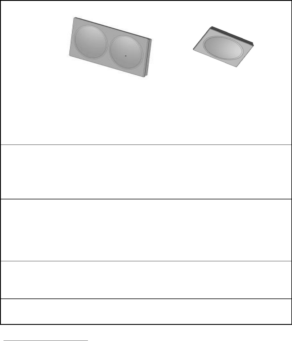
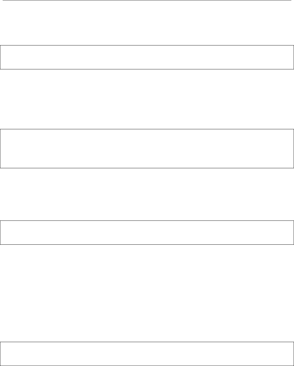
communicates with a host computer using standard Ethernet TCP/IP and UDP protocol. Figure 1
illustrates the Four versions of SASL currently available. All models are equipped with identical
Array Controllers. The ITCS-A-210 and ITCS-A-212 contain the RF Controls RFC-6100XR RFID
reader.
ITCS-A-210 are constructed using eight Bi-directional Electronically Steerable Phased
Arrays (BESPA™) arranged to provide a single array with a circularly polarized gain of more
than 10dBi.
ITCS-A-212 are constructed using four BESPAs arranged to provide a single array with a
circularly polarized gain of more than 7 dBi.
The particular units used in an installation will depend on the system design and determined by a
qualified applications engineer. The two models may be intermixed as required in a single ITCS
system.
ITCS-A-210
ITCS-A-212
Figure 1 SASL (Signal Acquisition and Source Location) Units
SASL User Guide v1.40 - Part # ITCS-A-100-001 v1.40 May 2014
4
INDICATOR LIGHTS
ITCS-A-21X Reader Indicator Lights
The RF Controls RFC-6100XR RFID reader is equipped with four status indicators located on the
top of the enclosure. From top to bottom, these LEDs provide indication according to the following
table:
Indication
Color/State
Indication
Tag Sense
Off
No Tags Detected
Blue
Tags Detected
Transmit
Off
RF Off
Yellow
Transmit Active
Fault
Off
OK
Red-Flashing
Error/Fault Blink Code
Power
Off
Power Off
Green
Power On
Note that when the RFC-6100XR reader is performing power on auto-test, the indicator lights will
flash momentarily.
Figure 2 RF Controls RFID Reader Indicator Lights.

SASL User Guide v1.40 - Part # ITCS-A-100-001 v1.40 May 2014
5
Installation
MECHANICAL INSTALLATION
Each model of the ITCS-A-21X family of SASL units is mounted slightly differently. SASL units
weigh up to 100 lbs (46.3 kg), so it is important to ensure that the structure, to which the SASL is to
be attached, is of sufficient strength. The SASL may be ceiling mounted, wall mounted or attached
to a suitable stand. A safety cable rated at three (3) times the hanging weight of the SASL and
associated hardware must be secured to a separate fixture and attached to the SASL mounting
bracket.
When mounting the SASL as a stand-alone unit, make sure that it is mounted the correct way up as
indicated by information in the Technical Manual, for the specific SASL. If the SASL is one of
several and is part of an ITCS network, then orient each SASL according to the ITCS system
installation drawings. If in doubt contact a member of our technical support team.
ITCS-A-210
The ITCS-A-210 SASL is provided in its standard configuration with a mounting bracket for
installation in a landscape orientation. When mounting the SASL refer to Figure 4. Consult the
Technical Manual, for further information. Contact a member of our technical support team for
more information.
ITCS-A-212
The ITCS-A-212 SASL is only mounted in a landscape orientation because the array is
symmetrical, there is no benefit to mounting the array in a portrait fashion. When mounting the
SASL refer to Figure 4. Consult the Technical Manual, for further information. Contact a member
of our technical support team for more information.
When mounting the SASL as a stand-alone unit, make sure that it is mounted the correct way up as
indicated by information in the Technical Manual, for the specific SASL. If the SASL is one of
several and is part of an ITCS network, then orientate each SASL according to the ITCS system
installation drawings. If in doubt contact a member of our technical support team.
SAFETY WARNING
The ITCS-A-200 SASL weighs approximately 100 lbs. (49 kg), and ITCS-A-202 weighs
approximately 50 lbs (23kg). These units should only be installed using suitable safety and
lifting equipment. Ensure that the wall fixings or mounting hardware is suitably rated.
AVERTISSEMENT DE SÉCURITÉ
ITCS-A-200 SASL pèse environ 49 kg, et des ITCS-A-202 pèse environ 23 kg. Ces unités
ne doivent être installés à l'aide des équipements de sécurité et de levage approprié.
Veiller à ce que les fixations murales ou le matériel de montage est convenablement
évalués.
SASL User Guide v1.40 - Part # ITCS-A-100-001 v1.40 May 2014
6
ELECTRICAL INSTALLATION
POE Power Input
POE power input is available only for the ITCS-A-210 and ITCS-A-212 using the RJ-45 connector
as shown in Figure 4. Connect POE power supply and plug it in to a suitable mains outlet and the
POE Bias T. POE power, DC Input equivalent to IEEE 802.3at. Note that the power for the POE
bias T should be located in close proximity to the SASL and should be accessible to enable easy
disconnection of the power to the SASL in case of emergency or when servicing.
AC Mains Input
AC mains input is an IEC connector as shown in Figure 4. Connect the provided IEC mains cord to
the power supply and plug it in to a suitable mains outlet. Note that the mains outlet must be
located in close proximity to the SASL and must be accessible to enable easy disconnection of the
mains supply to the SASL in case of emergency or when servicing. The form and location of the
AC mains input is the same on the ITCS-A-210 and ITCS-A-212.
Ethernet
The Ethernet LAN connection uses the industry standard RJ-45 connector. A suitable Ethernet
cable fitted with an RJ-45 plug is connected to the SASL Array Controller box as shown in Figure 4.
The SASL is factory programmed with a fixed IP address which is shown on the label adjacent to
the Ethernet connector. The form and location of the Ethernet connection Input is the same on the
ITCS-A-210 and ITCS-A-212.
Figure 4
ITCS-A-210 and ITCS-A-212 Power and Ethernet Connections are similar in form and location.

SASL User Guide v1.40 - Part # ITCS-A-100-001 v1.40 May 2014
7
WARNING
The SASL is not user serviceable. Disassembly or opening the SASL will cause damage to
its operation, will void any warranty and may invalidate the FCC type approval
Non Ionizing Radiation
This unit incorporates a Radio Frequency Transmitter and should therefore be installed and
operated so as to avoid exposure of any persons to unsafe emissions. A minimum separation
distance of 23cm must be maintained at all times between antenna and all persons. See FCC
Radiation Exposure Statement in the Safety Instructions section of this guide.
Notice for European Installers
The Installer shall ensure that he is familiar with any restrictions of the local EU Member State on
the use of this device and ensure compliance! Examples may include: restrictions on geographic
location or only for indoor use etc.
Due to differences between ETSI and FCC frequency bands, “Phase Ranging” Techniques are not
available with the ETSI version of the SASL.
Usable Frequency Range in US and Canada
In USA and Canada this device is factory programmed to operate in ISM 902MHz – 928MHz band.
SASL User Guide v1.40 - Part # ITCS-A-100-001 v1.40 May 2014
8
MULTIPLE SASL UNITS CONFIGURED AS AN ITCS
Figure 5 shows how two or more ITCS-A-21X SASL units may be connected via an Ethernet
network to an ITCS Location Processor. One Location Processor and multiple distributed SASLs
operate collaboratively to form RF Controls’ Intelligent Tracking and Control System (ITCS™). In
this example two SASL units have been attached to the network. Combinations of the various
model SASL units may be mixed and matched as required to suit a particular installation. The RF
Controls Technical Manual provides details on how to install, configure and calibrate an ITCS.
The Programmers Reference Guide provides details of the Application Program Interface (API)
used by the ITCS.
Figure 5
Intelligent Tracking and Control System comprising a number of SASL units connected via an
Ethernet Network to an ITCS Location Processor

SASL User Guide v1.40 - Part # ITCS-A-100-001 v1.40 May 2014
9
Software
The SASL is provided with a basic test program on a CD, to run on a Microsoft™ Windows®
equipped Personal Computer. The program enables you to carry out a number of basic tests.
See the Technical Manual for further instruction on Software usage.
APPLICATION INTERFACE
The SASL uses an International Standard, Application Program Interface (API) as defined in
ISO/IEC 24730-1. Further details of the API and commands are contained in the Programmer’s
Reference Guide.
SASL User Guide v1.40 - Part # ITCS-A-100-001 v1.40 May 2014
10
Specifications
General
ITCS-A-210
ITCS-A-212
Frequency
UHF band: 860 – 960 MHz1
RF Radiated Output
Power
Adjustable from 0.2 to 4 Watts EiRP
Regulatory Compliance
FCC, CFR47 Part 15.247
EN 302 208, EN 301 489-3, EN 301 489-1,
EN55022, EN55024, EN 60950-1:2005
Reading/writing
Protocols
ISO18000-6C / EPC UHF Gen 2
EM 4122 (TTO)
FCC ID IC ID
WFQRFC-6100XR 10717A-RFC6100XR
Application Interface
ISO/IEC 24730-1
Environmental
Operating Temperature
+14 to +130 °F (-10 to +55°C)
Storage Temperature
-40 to +85ºC
Relative Humidity
5 to 95% non-condensing
Dimensions
68in x 36in x 5in
(170 x 90 x 13 cm))
36in x 36in x 5in
(90 x 90 x 13 cm)
Weight
100 lbs (46 kg)
54 lbs (25 kg)
Ethernet LAN
Connector
RJ-45
Ethernet
10/100 BaseT
Indicators
Yellow – link operational
Green – network traffic detected
Signals
Pin 1
TXD +
Pin 5
NC
Pin 2
TXD -
Pin 6
RXD -
Pin 3
RXD +
Pin 7
NC
Pin 4
NC
Pin 8
NC
Power Supply
AC Mains Input
POE DC Input IEEE 802.3at
Input Connector
IEC/EN 60320 C14
RJ-45
Voltage
90 – 265 Volts AC
+48V
Frequency
47 – 63 Hz
DC
Current
3A
0.7A
Antenna
Gain2 (circularly
polarized)
TBD dBi2
TBD dBi2
1
The SASL uses the RFC RFC-6100XR RFID reader which will be factory set at time of shipping, to suit the
country of installation and use.
2
To Be Determined at test. Nominal maximum value. Precise gain depends on transmit frequency
SASL User Guide v1.40 - Part # ITCS-A-100-001 v1.40 May 2014
11
Safety Instructions Consignes de Sécurité
This unit emits Radio Frequency non-ionizing radiation. The installer must ensure that the antenna
is located or pointed such that it does not create an RF field in excess of that permitted by the
Health and Safety Regulations applicable to the country of installation.
Cet appareil émet Radio Fréquence rayonnements non ionisants. L'installateur doit s'assurer que
l'antenne est située ou orientée de façon à ne pas créer un champ RF supérieure à celle permise
par le Règlement sur la santé et applicable dans le pays d' installation.
Setting RF Output Power
Enter the desired RF output power as a percentage of the maximum power into the Set Power box.
Click the set Power button. Note: the actual maximum Radiated RF Power is factory set to comply
with the radio regulations in the country of use. In the USA and Canada this is 4 Watts EiRP and
under EN 302 208 this is 2 Watts ERP (3.2 W EiRP).
Entrer la puissance de sortie RF souhaité sous forme d' un pourcentage de la puissance maximale
dans la zone d'alimentation Set. Cliquez sur le bouton ensemble d'alimentation . Remarque: le
maximum réel rayonnée de puissance RF est réglé en usine pour se conformer à la réglementation
de radio dans le pays d'utilisation. Aux Etats-Unis et au Canada c'est 4 Watts EiRP et selon la
norme EN 302 208 c'est 2 watts ( 3,2 W PIRE).
FCC Radiation Exposure Statement
The antenna used on this equipment must be installed to provide a separation distance of at least
23cm from all persons and must not be co-located or operated in conjunction with another antenna
or transmitter.
L'antenne utilisée sur cet équipement doit être installé pour fournir une distance de séparation d'au
moins 23cm de toutes les personnes et ne doit pas être co- implantés ou exploités conjointement
avec une autre antenne ou émetteur .
FCC Part 15 Notice
This device complies with part 15 of the FCC Rules. Operation is subject to the following two
conditions: (1) This device may not cause harmful interference, and (2) this device must accept any
interference received, including interference that may cause undesired operation.
FCC and Industry Canada Modification Warning Statement
Modification of this device is strictly prohibited. Any modifications to the factory hardware or
software settings of this device will void all warranties and be deemed non-compliant with FCC and
Industry Canada Regulations.
La modification de ce dispositif est strictement interdite. Toutes les modifications apportées au
matériel d'usine ou les paramètres du logiciel de cet appareil annulera toutes les garanties et sera
considérée comme non conforme aux normes FCC et d'Industry Canada.
SASL User Guide v1.40 - Part # ITCS-A-100-001 v1.40 May 2014
12
Industry Canada Statement
This device complies with Industry Canada licence-exempt RSS standard(s). Operation is subject
to the following two conditions: (1) this device may not cause interference, and (2) this device
must accept any interference, including interference that may cause undesired operation of the
device.
Cet appareil est conforme aux normes d'Industrie Canada exempts de licence(s) RSS. Son
fonctionnement est soumis aux deux conditions suivantes: (1) cet appareil ne doit pas provoquer
d'interférences, et (2) cet appareil doit accepter toute interférence, y compris les interférences qui
peuvent provoquer un fonctionnement non désiré de l'appareil.
Power Disconnect Device
The plug on the power supply cord is intended to be the power disconnect device. The power
source (socket or outlet) shall be located near the equipment and shall be easily accessible.
La fiche du cordon d'alimentation est destiné à être le dispositif de coupure de courant. La source
d'alimentation (prise ou sortie ) doit être située près de l'équipement et doit être facilement
accessible .
Statement of Compliance with R&TTE Directive
RF Controls, LLC hereby declares that it’s ITCS-A-200, and ITCS-A-202 products are in compliance
with the essential requirements and other relevant provisions of European Directive 1999/5/EC.
The original Certificate of Conformity is available at www.rf-controls.com
The SASL products and individual BESPA components are protected by one or more US and
International Patents pending.
The “RF Controls” logo, and the words “RF Controls, Identify, Locate, Track”, “ITCS”, “SASL” and
“BESPA” are registered Trademarks of RF Controls, LLC.
RF Controls, LLC
1400 South 3rd Street, Suite 220
Saint Louis, MO 63104-4430
USA
Phone: +1 314 584-1500 +1 314 571-6200
Fax: +1 314 584-1549
e-mail: techsupport@rf-controls.com
Web site: http://www.rfctrls.com e-mail: inquires@rf-controls.com