RF DataTech ART400 ART 400 Series Radio Modem User Manual ART 400 Ver 1 2 Rev1

RF DataTech ART 400 Series Radio Modem ART 400 Ver 1 2 Rev1

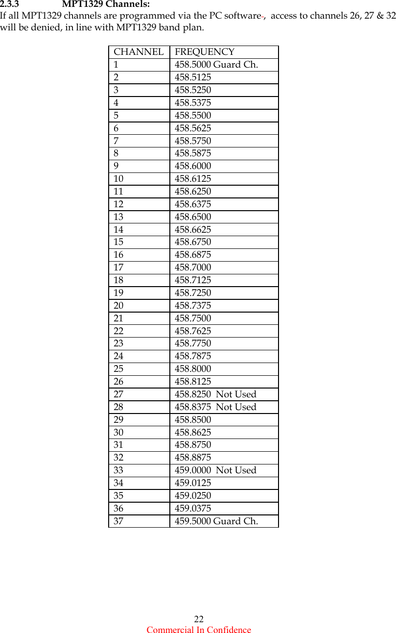
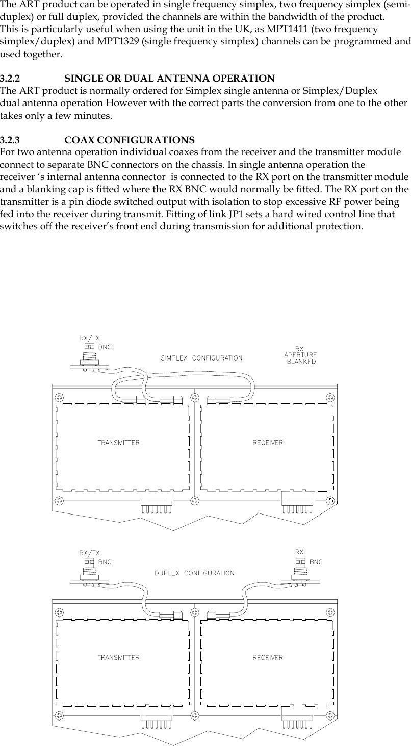
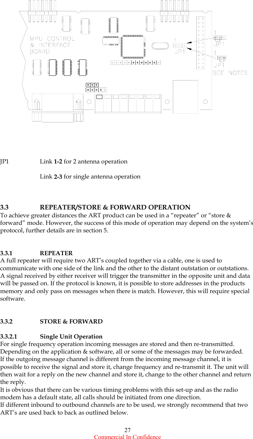
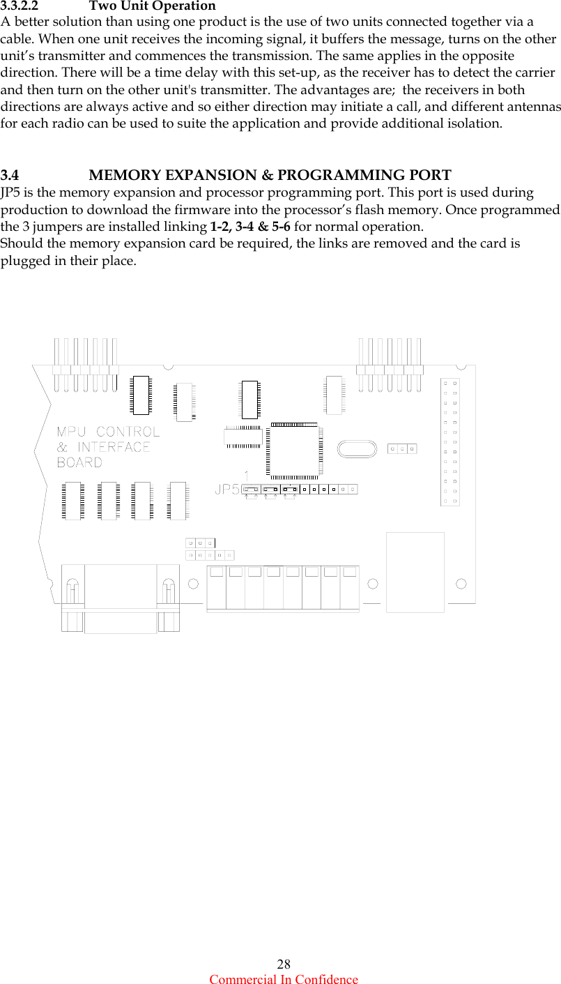
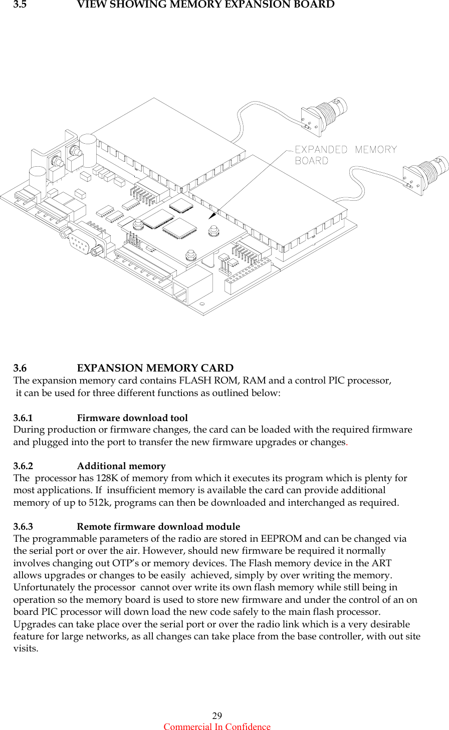
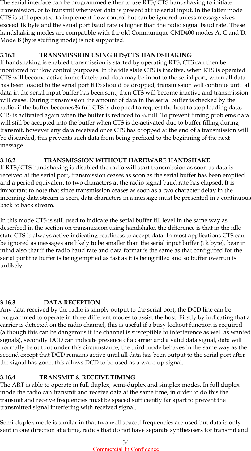
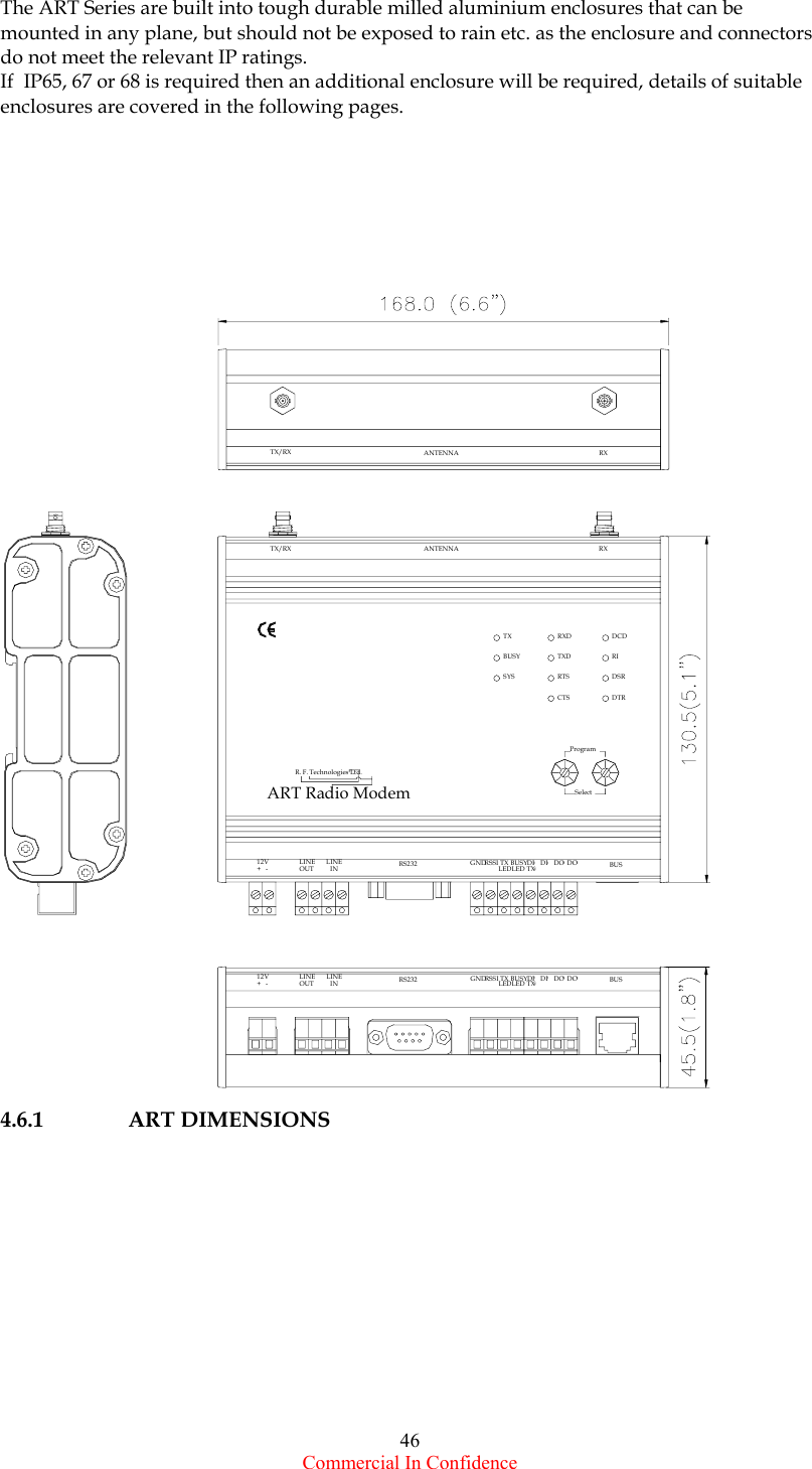
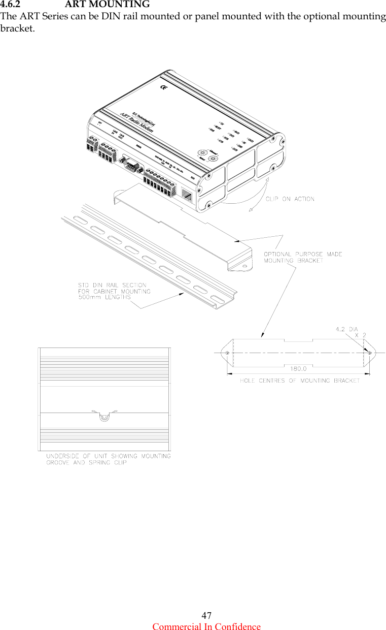
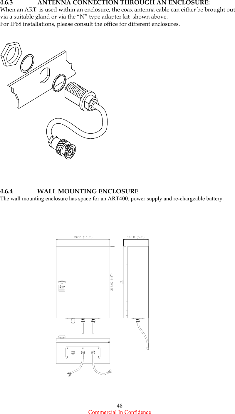
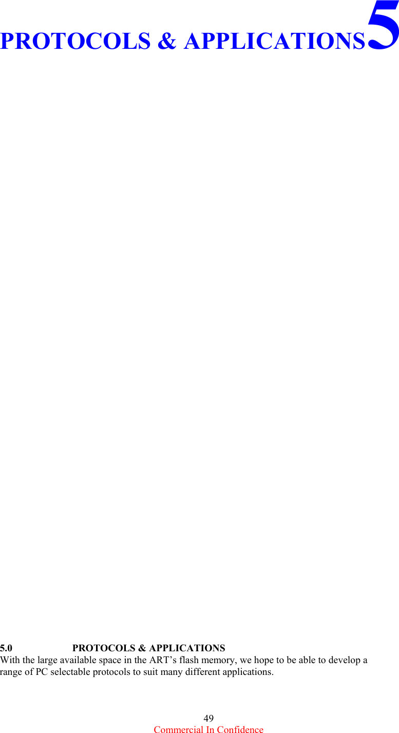
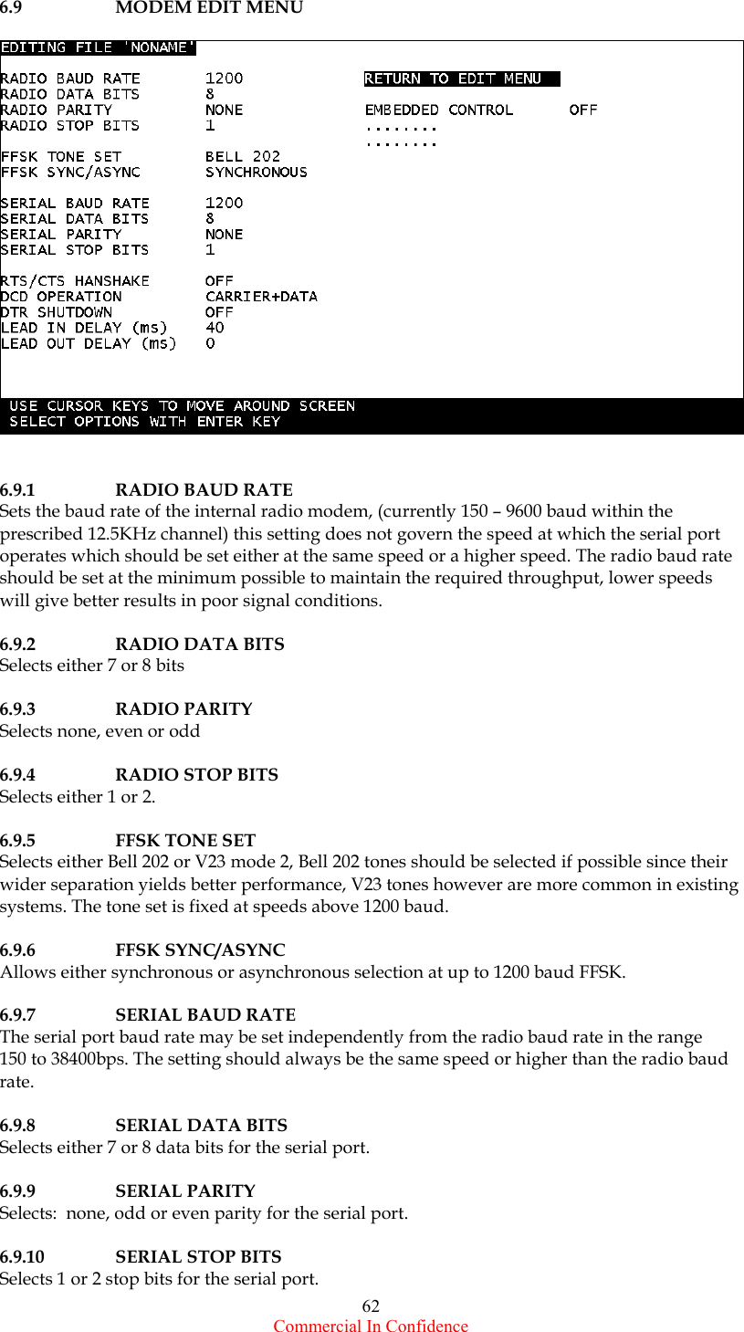
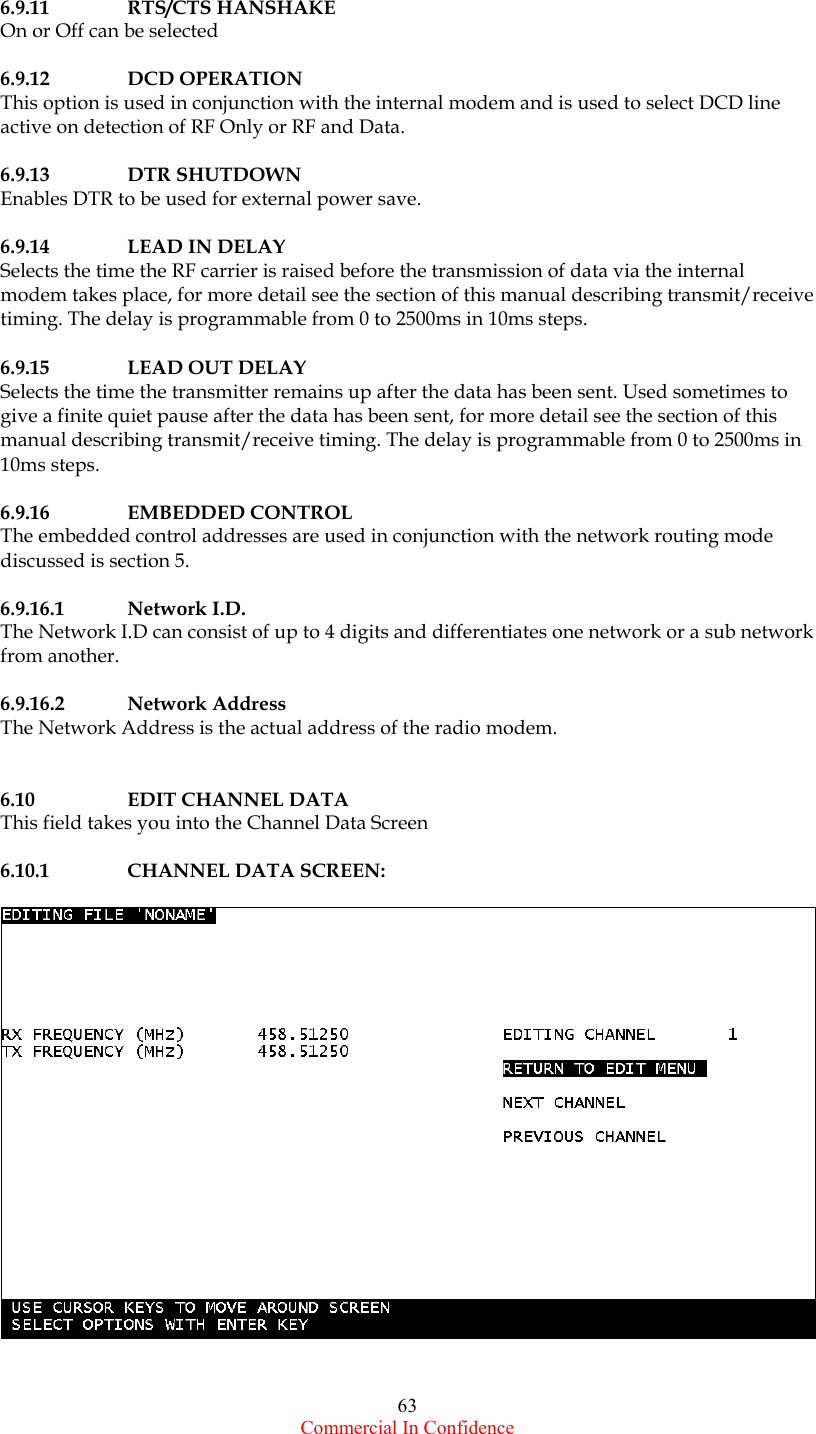
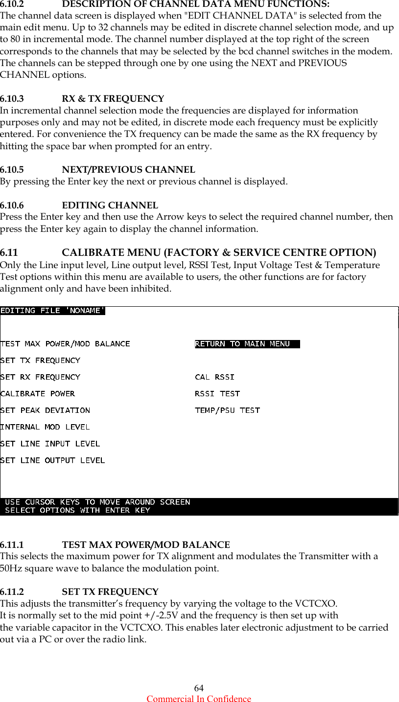
ART 400 Series Installation Operation and Programming Manual

   ART SERIES   INSTALLATION, OPERATION & PROGRAMMING MANUAL               COVERS ART400, (ART400T), (ART400R) SYNTHESISED  RADIO MODEMS & REPEATERS  October 2001 ISSUE  1.  rev1.2
 Commercial In Confidence 2  CONTENTS   1.0      INTRODUCTION    1.1                Products Covered 1.2     Introduction 1.3   Overview 1.3.1    Radio Frequency (RF) Section 1.3.2    Transmitter 1.3.3    Receiver 1.3.4      MPU Control & Interface Board 1.3.5      Software 1.3.6   Custom Software 1.3.7   Continuos Development 1.4               Channel Selection 1.5   Programmability 1.6    Low Power operation 1.7   Power Save Mode 1.7.1   Internal Power Save Mode 1.7.2   External Power Save Mode 1.7.3   Time Scheduling using the RTC 1.8    Soft Modem    1.9    RSSI Receive Signal Strength Indicator 1.10   Status LED’s 1.11    Optional Keypad & Display  1.12   R.F. Power 1.13    Local I.O.    1.14    12C Internal & External BUS 1.15   GPS   1.16    Internal/External Modem Operation 1.16.1 External       1.16.2  Tone Operated Switch (TOX) 1.16.3 Internal 1.17    Modes of Operation & Protocol Handling 1.17.1  Radio Modem Modes of Operation 1.17.1.1 Dumb Modem 1.17.1.2 Protocol Specific Modem 1.17.1.3 Routing Modem 1.17.1.4 Dial-up Modem 1.17.2  I.O. Modes of Operation 1.17.2.1  Isolated Network with Point to Point I/O Mapping 1.17.2.2  Network with Retrieved Data Access at Base Station 1.17.2.3 Externally Controlled Network 1.17.2.4 Custom Protocols 1.18    Network Management Software 1.19   Squelch Tail Elimination 1.20    Forward Error Correction 1.21  Automatic Frequency Control    1.22   TX Time-Out-Timer 1.23    Dual Control for Fully Duplicated Outstation 1.24    Programming, Service Installation & Management    Software 1.24.1 Programming Software 1.24.2 Installation Software  1.24.3 Service Software 1.24.4  Network Management Software
 Commercial In Confidence 3 1.25    Compatibility with other products   2.0      SPECIFICATIONS      2.1   Technical Specification: 2.1.1      General 2.1.2      Transmitter 2.1.3      Receiver 2.1.4      Internal Modem 2.1.5   Bit Error Rates 2.2     Approvals and Licensing 2.2.1   UK Approvals 2.2.2   European Approvals  2.2.3   Other Approvals  2.3     Operating Channels 2.3.1   UK Telemetry Channels 2.3.2   MPT1411 Channels 2.3.3   MPT1329 Channels 2.4        Options & Accessories 2.4.1   DIN Power Supplies with Chargers 2.4.2   DIN Mounting RF Power Amplifiers    2.4.3   DIN I/O Modules 2.4.4   Leads & Cables  2.4.5   RF Adapters & Parts 2.4.6   Enclosures 2.4.7   Manuals   2.4.8   Backup Batteries 2.4.9   Antennas    3.0    OPERATION AND INTERFACE   3.1   Exploded View 3.2    Operation & Interface Description 3.1.1   Simplex, Semi-duplex & Full Duplex 3.3.2   Single or Dual Antenna Operation 3.3.3   Coax Configurations 3.3   Repeater/Store & Forward 3.3.1   Repeater 3.3.2   Store & Forward 3.3.2.1  Single Unit Operation 3.3.2.2  Two Unit Operation   3.4    Memory Expansion & Programming Port 3.5    View Showing Memory Expansion Board 3.6    Memory Expansion Board 3.6.1   Firmware Download Tool 3.6.2   Additional Memory 3.6.3   Remote Firmware Download Module 3.7    Serial and RS232 Interface 3.8    Serial Port Pin Connections 3.9   Antenna Connections 3.10   12VDC Power 3.11    I2C BUS Interface 3.12    Audio & Line Interface 3.13   Switches 3.14   Control Interface 3.15   External Audio Path 3.16   Internal Modem 3.16.1  Transmission using RTS/CTS Handshaking
 Commercial In Confidence 4 3.16.2  Transmission without Hardware Handshaking 3.16.3 Data Reception 3.16.4  Transmit & Receive Timing 3.16.4.1  Receiver to transmitter Switching Times 3.16.4.2 Message Duration 3.16.4.3  Transmit to Receive Switching Times   3.16.5  Radio Data Format 3.16.6 Synchronous/Asynchromus Format 3.16.7 Transmit/Receive Timing 3.17   Error Reports 3.18     Time Out Timer 3.19     Power Save Mode 3.20   RSSI Output 3.21              Temperature Measurement 3.22    Input Voltage Measurement 3.23   Real Time Clock. 3.24   External I.O.   4.0   INSTALLATION  4.1   Introduction 4.2   Power Supplies 4.3    Effective Radiated Power (ERP) 4.4   Safe Distance Calculation 4.5    Antennas, Coax Feeders & Peripherals 4.5.1   Antennas 4.5.2   Types of Antennas 4.5.3   Omni-Directional Antennas 4.5.4   Directional Antennas 4.5.5   Patch Antennas 4.5.6   Antenna Mounting 4.5.7   Polarisation 4.5.8   Alignment 4.5.9   Antenna Coax Feeder 4.5.10  Cable length Verses Signal Loss at 500MHz 4.5.11 Coax Connectors 4.5.12 VSWR Measurement 4.5.13 Lightning Arresters 4.6   Mounting 4.6.1   ART Dimensions 4.6.2   ART Mounting 4.6.3   Antenna Connection an enclosure       4.6.4   Wall Mounting Enclosure    5.0    PROTOCOLS & APPLICATIONS  5.1    Store & Forward Using Clients Protocol 5.2   Network Routing Mode 5.2.1   AT Command Set 5.2.2   Power Saving 5.2.3   Call Set Up Procedure 5.2.4   Radio Routing 5.2.5   Wake Up Procedure 5.2.6   Implementing Registers   6.0     PROGRAMMING
 Commercial In Confidence 5 6.1     Introduction 6.2          Medium 6.3     Configuration of the A4P Program 6.4     Starting the Program 6.5    Connecting the ART for local PC Programming 6.6   Programming/Reading Radio 6.7   Opening Menu 6.7.1   Directory Display 6.7.2   Version Number & Compatibility Message 6.7.3   Edit Notes 6.8    Description of Main Edit Functions 6.8.1   Main Menu 6.8.2   Radio Mode 6.8.3   Frequency Range 6.8.4   Alignment Range 6.8.5   Channel Selection Mode 6.8.5.1  Number of Channels 6.8.5.2 Channel Increments 6.8.5.3  RXD Start Frequency 6.8.5.4  TX Start Frequency 6.8.6   Power Range 6.8.7   TX Power 6.8.8   Power Save Options 6.8.8.1 Save On Time 6.8.8.2  Save Off Time 6.8.8.3  Save Resume Time 6.8.9   Serial Number 6.8.10 Note Pad 6.8.11 Lockout Time Mode 6.8.12 Lockout Time 6.8.13 Audio Response 6.8.14 Carrier Mute 6.8.15 Menu Options 6.8.15.1  Return to Main Menu 6.8.15.2 Edit Channel Data 6.8.15.2 Edit Modem setup 6.8.15.3 Custom Menus 6.9   Modem Edit Menu 6.9.1   Radio Baud Rate 6.9.2   Radio Data Bits 6.9.3   Radio Parity 6.9.4   Radio Stop Bits 6.9.5   FFSK Tone Set 6.9.6   FFSK/SYNC/ASYNC 6.9.7   Serial Baud Rate 6.9.8   Serial Data Bits 6.9.9   Serial Parity 6.9.10 Serial Stop Bits 6.9.11 RTS/CTS Hanshake 6.9.12 DCD Operation 6.9.13 DTR Shutdown 6.9.14  Lead In Delay 6.9.15 Lead Out Delay 6.9.16 Embedded Control 6.9.16.1 Network I.D 6.9.16.2 Network Address 6.10    Edit Channel Data 6.10.1 Channel Data Screen 6.10.2  Description of Channel Data Menu Options 6.10.3  RX & TX Frequency 6.10.4 Next/Previous Channel
 Commercial In Confidence 6 6.10.5 Editing Channel   6.11    Calibrate Menu (Factory & Service Centre Options) 6.11.1  Test Max Power/Mod Balance 6.11.2 Set TX Frequency 6.11.3  Set RX Frequency 6.11.4 Calibrate Power 6.11.5 Set Peak Deviation 6.11.6  Internal Mod Level 6.11.7 Set Line Level 6.11.8 Cal RSSI  6.11.9 RSSI Test 6.11.10 Temperature Test 6.11.11  Input Voltage Test   6.11.12  Return to Main Menu   SOFTWARE & ANCILLARYITEMS  7.1   PC Software 7.2    Client  Programming Software 7.3    Factory Programming Software 7.4    Bit Error Rate (BER) Software 7.5    Test & Alignment Software 7.6    Network Management Software 7.6.1   Installation                    7.6.2              Operation within a network           7.6.3              Additional Features           7.6.4               Internal Temperature measurement           7.6.5              Input Power Supply Voltage           7.6.6              RX & TX Offset Frequency Measurement           7.6.7              & TCXO re-alignment             7.6.8               Local/Remote firmware upgrades          7.7               Future Software Developments            7.7.1               Non Intrusive Network management software            7.8               Ancillary Products           7.8.1               Power Supplies with Chargers           7.8.2               RF Power Amplifiers           7.8.3               DIN I.O. Modules           7.8.4               Enclosures           7.8.5               Leads & Cables           7.9               Adapters & Parts           7.10               Manuals            7.11               Backup Batteries           7.12               Antennas
 Commercial In Confidence 7 FCC Compliance Statement  This device complies with part 15 of the FCC Rules. Operation is subject to the following two conditions: (1) This device may not cause harmful interference, and (2) this device must accept any interference received, including interference that may cause undesired operation.   WARNING  Changes or modifications not expressly approved by the party responsible for compliance could void the user’s authority to operate the equipment.  NOTE: This equipment has been tested and found to comply with the limits for a Class A digital device, pursuant to part 15 of the FCC Rules. These limits are designed to provide reasonable protection against harmful interference when the equipment is operated in a commercial environment. This equipment generates, uses, and can radiate radio frequency energy and, if not installed and used in accordance with the instruction manual, may cause harmful interference to radio communications. Operation of this equipment in a residential area is likely to cause harmful interference in which case the user will be required to correct the interference at his own expense.  Industry Canada Certification  This device complies with Industry Canada RSS 119, under certification number TBD.   IC Class A Compliance  This device complies with the Class A limits for radio noise emissions as set out in the interference-causing equipment standard entitled “Digital Apparatus,” ICES-003 of Industry Canada.   WARNING  To satisfy FCC/IC RF exposure requirements for mobile transmitting devices, a separation distance must be maintained between the antenna of this device and persons during operation.  To ensure compliance, operations at closer than this distance in not recommended.  The following table show this distance for different gain of antennas:  Gain of Antenna (dB) Minimum Separation Distance (metre) Unity 0.5 3 0.7 6 1.0 8 1.3 10 1.6 12 2.0
 Commercial In Confidence 8  INTRODUCTION1   1.1      PRODUCTS COVERED  This Manual covers the R.F. Technologies ART Series Radio Modems and repeaters.  Information is provided to program, install, and operate the products in various  configurations.  With the built-in test software, first line “Go-No Go” testing can be easily performed. Component level servicing is not covered in this document, if the product fails its first line testing it should be returned to a service centre.   1.2          INTRODUCTION       The ART Series are high performance, very low current consumption, dual  Synthesised Radio Modems,  designed specifically for the Telemetry and Data market, where the fast transfer of data is required over reliable wireless links.   The ART was designed as a result of research into market requirements for a product that would work in a large majority of applications. As a result the ART will fit into almost any system using licensed, or license exempt telemetry channels in the VHF, UHF & 900MHz bands.   The  ART product is unique in its use of a single flash microprocessor to control both the RX & TX radio modules, external interfaces, and function as a full duplex modem with programmable speeds up to 9600bps.    1.3          OVERVIEW  1.3.1    RADIO FREQUENCY (RF) SECTION The ART employs separate receiver and transmitter modules connected to a common microprocessor and interface board. The RF modules have separate synthesisers to enable  full duplex operation and in simplex operation facilitates very fast turn around times. The ART has been specially designed with very low group delay filters to provide the best path for high speed data signals. Each RF module is a self contained unit, that plugs into the control board and in the unlikely event that a R.F unit fails, it can be easily replaced and sent to our service centre for repair.   No attempt should be made to repair the unit except by experienced RF personnel with Proper RF test equipment is available.  NOTE: Adjusting any of the controls within the RF module may degrade the transceiver's performance or put its operation outside the approved specification.   1.3.2    TRANSMITTER The transmitter can be programmed anywhere within a pre-aligned bandwidth, which is within a wider tuneable F band, details of the bandwidths are in the technical specifications. Both High power (20mW – 5Watts) and low power (10mW – 1Watt) products are available. For ease of  operation, all parameters are PC programmable with channel change duplicated on the external switches.
 Commercial In Confidence 9     1.3.3    RECEIVER The receiver is a very low current double conversion  superheterodyne with an active balanced mixer for very good intermodulation. Careful attention to spurious response, adjacent channel and blocking performance, makes the product ideal for crowded telemetry channels.   1.3.4    MPU CONTROL & INTERFACE BOARD The Microprocessor (MPU) control & interface board is the heart of the product and at the centre is a 128K flash microprocessor that controls all the interface circuits to the radio modules and external Input/outputs. As well as the control functions, the processor provides DSP functionality that enables full duplex modem operation between 150 – 9600bps.   The board also contains all necessary electronic potentiometers for full remote alignment and control, these settings and other parameters are stored within the MPU ‘s non-volatile EEPROM.   1.3.5 SOFTWARE The processor has 128K of flash memory from which the code is executed and EEPROM for storing programmed parameters. This ensures plenty of room for future upgrades and custom applications.   1.3.6 CUSTOM SOFTWARE Custom software or protocols for specific client applications, can be written and included  as PC programmable options in relatively short time scales and normally at nominal costs. Further details can be obtained from the sales office.  1.3.7 CONTINUOUS DEVELOPMENT The ART series has been designed with continuous development in mind and with less than one third of the code space currently in use, there is plenty of room for protocols such as MODBUS & TCPIP. For additional space (should it be required) a piggy back memory board with  a further 512k is available to download new code to the processor.  The fact that the product may have been deployed in the field, before changes have been made, makes no difference, as changes and upgrades can easily be sent over the radio link via our secure over air programming protocol.   1.4   CHANNEL SELECTION The ART Series can be PC programmed with up to 80 discrete channels. Alternatively, complete band allocations like the UK MPT1329 and MPT1411 bands can be downloaded from the PC software,  provided of course that the channels are within the products tuneable bandwidth.   Once programmed, channels can then be selected via rotary switches on the front panel (or via the keypad on the display version) , from a PC program, via the serial port or over the radio link.   1.5   PROGRAMMABILITY Apart from one or two link selectable options (like single/dual antennas) , all the parameters of the ART Series can be programmed via the serial port using either  DOS or Windows 95/98 based software or over the radio link via the ART’s secure “over air programming mode”.  The individual program can be stored on disc for future use or printed.
 Commercial In Confidence 10       1.6    LOW POWER OPERATION The ART’s processor controls all the circuitry and power saves as a matter of course.  With no large DSP chips taking heavy current loads, the ART has probably the lowest current consumption of any comparable radio modem on the market.   Although the 5watt product has very low current consumption, for extremely low current applications the 1Watt version is recommended.    1.7   POWER SAVE MODE The ART Series has both internal and external power save modes.     1.7.1    Internal Power Save Mode The microprocessor controls the on/off function of the receiver and after a pre-programmed time the MPU will switch on the receiver to look for a carrier.  If a carrier is not detected, the transceiver goes back into sleep mode.   If during the time the transceiver is awake a carrier is received, the unit will stay awake.   After the carrier drops out, the receiver will stay awake until the programmed resume time elapses.   Once the resume time has elapsed the transceiver will go back into sleep mode.   The save ON/OFF and resume time are all programmable via the PC program.  1.7.2    External Power Save Mode In the external mode the ON/OFF function of the modem is controlled by the host via the DTR line.  1.7.3   Time Scheduling using the RTC  The ART contains an embedded Real Time Clock that can be used to wake the radio modem to process information, report back or be ready for a poll. The RTC can be synchronised during the wake-up communication for accurate time slotting. Note this mode is not currently in use but will be implemented in the on going software development.   1.8   SOFT MODEM The ART features a full duplex  “soft modem” which offers unparalleled performance and flexibility over a wide range of speeds and formats and enables future formats to be downloaded from a PC or over the air.  Within a 12.5KHz channel, the unit can be programmed for 150-2400bps FSK/FFSK with Bell202 & V23 supported,  4800bps GMSK & 9600bps 4 Level FSK.   1.9    “RSSI” RECEIVE SIGNAL STRENGTH INDICATION Each ART has an internal individually calibrated RSSI signal which is accurately measured by an internal A-D converter. The signal strength can then be read in dB micro volts on a PC connected to the serial port or remotely over the air.   In the case of the LCD version the level can be directly read from the display. Alternatively the raw 0-5VDC relative to the RSSI is available on one of the connectors.
 Commercial In Confidence 11 1.10   STATUS LED’s: The ART has 11 LED’s to enable the operator to see at a glance the status of the product and the serial port in operation or on test.    1.11    OPTIONAL KEYPAD & DISPLAY Provision has also been made in the design to accommodate the development of a keypad and liquid crystal display (LCD) for local programming without the use of a PC and for displaying the status of the product and connected I.O. modules.     1.12   RF POWER: The ART’S are available in two power ranges:  10mW to 1 Watt for ultra low power requirement, and 20mW to 5 Watts. The calibrated RF power level is PC and over air programmable directly in watts & milli-watts with an accuracy of +/-1dB. For high power (5-25Watt) applications a DIN power amplifier is available.    1.13    LOCAL DIGITAL I.O. The ART Series has two local inputs and two outputs that can be configured and used under the management and diagnostics software.  For additional analogue or digital I.O the ART700 Series of I.O. modules can easily be connected to the I2C bus interface.    1.14    I2C INTERNAL & EXTERNAL BUS  The ART Series features an I2C Bus which is used to communicate with other modules over short or medium distances. The main feature of the bus is its address mode, which will only wake up modules that are being addressed, thereby ensuring low power operation.         At the time of writing this manual a full range of analogue and digital I.O. modules are under development, a list of them are in the specification section, with further details are available from the sales office.  1.15   GPS The ART Series can have a GPS module connected via the I2C bus, this enables time & date stamping and asset tracking or more importantly, the location of nodes in large systems where the downloading of network changes to specific nodes may be required.     1.16    INTERNAL/EXTERNAL MODEM OPERATION: Both internal and external modems are supported, the external interface provides both flat and de/pre-emphasised response for compatibility with older systems.  1.16.1   External In external mode the 600 ohm input and output will accommodate a programmable  range of  +3dBm to –20dBm.   The output can be muted in the absence of a carrier.  1.16.2    Tone Operated Switch (TOX)   When using an external modem via the 600 ohm port, the soft decoder within the ART400 can be programmed to detect incoming FFSK or PSK signals.   Once detected the transmitter will key up and pass the incoming data.  1.16.3   Internal The internal modem is PC programmable and is compatible with the many products in operation around the world. In the internal mode, data is presented to the modem via the RS232/TTL port at speeds up to 38400 and transmitted at the programmed baud rate. Buffering is provided when the data rate is higher than the transmission rate.
 Commercial In Confidence 12    1.17    MODES OF OPERATION & PROTOCOL HANDLING:  1.17.1    Radio Modem Modes of Operation The basic modes of operation of the radio modem are as follows:  1.17.1.1   Dumb modem The radio has no knowledge of the data it is transmitting, data is simply transmitted and received under hardware control with the option of RTS control or initiation of transmit after receipt of serial data, with CTS  providing an optional flow control.  This configuration is useful when expanding older systems where the radios must be compatible with others of a different manufacture.      1.17.1.2   Protocol specific modem The radio recognises a complete frame and only transmits and receives data conforming to that format. No addressing of radios or routing of data is performed. Protocols such as MODBUS & DNP3  can be supported in this way.   1.17.1.3   Routing modem The radios recognise a protocol specific frame and the address to which the frame is to be sent.  Routing information must be stored in each radio for each destination address that requires  the use of repeaters.  Any radio in the system can operate as a repeater.  The radio does not perform any acknowledgement or retries.  Any protocol using a fixed address field such as MODBUS can be supported.   1.17.1.4   Dial up modem Hayes protocol is used to dial up the radio link which may include repeaters or store & forward stations, the route information is not stored but is passed in the dial up command in the form of a telephone number, once the link is established it is transparent and so independent of the protocol being transported.  This allows point to point protocols such as SLIP and PPP (and hence TCP/IP) to be conveyed.  Dial up is less efficient for small data transactions because of the data exchanges carried out during the connect and disconnect phases.  1.17.2   I.O. Modes of Operation  1.17.2.1   Isolated network with point to point I/O mapping Inputs and outputs at outstations are mapped to corresponding outputs and inputs at the master.   1.17.2.2   Network with retrieved data access at base station. Instead of mapping data to physical inputs and outputs at the master, data is exchanged in memory.  The memory is accessible using MODBUS.  The base station carries out its data retrieval process independently of the MODBUS accesses.    1.17.2.3   Externally controlled network In this mode the base station only carries out data retrieval when requested to do so by the MODBUS interface. The above modes are not independent processes but are run according to set up, it is possible to configure operation to be a mix of all three.  E.g. some physical I/O might be desirable at the base station whilst the rest is passed by MODBUS, the base station can be set to keep polling independently in order to maintain the physical I/O but can also mix in commands passed by MODBUS.
 Commercial In Confidence 13 1.17.2.4   Custom Protocols Custom protocols can be written and downloaded via a PC or over the air as systems require change, thereby minimising disruption. Should a special protocol or interface be required please contact the sales office.    1.18   NETWORK MANAGEMENT SOFTWARE Network management software provides the user with direct access to the radio modems, for diagnostics, programming & re-programming, safe downloading of new firmware and the retrieval of data. All products on the I2C bus can be accessed in the same way.     1.19    SQUELCH TAIL  ELIMINATION For old or non tolerant protocols, where the presence of a mute (Squelch) tail may cause a problem at the end of a message,  a simple packetising option can be enabled.    1.20    FORWARD ERROR CORRECTION (FEC) Forward error correction is not implemented as standard in the modem because of the loss of throughput in good signal situations, however FEC can be offered as a custom option if required. Note that since the internal modem offers many data speeds data integrity can be improved simply by running a lower speed.   1.21   AUTOMATIC FREQUENCY CONTROL The network management software, enables the outstation’s receiver and transmitter to be frequency  locked onto the base station s frequency and automatically re-aligned, thereby minimising the effects of long term drift (ageing).   1.22   TX TIME-OUT-TIMER: The transmitter within the ART has a time-out-timer which allows the maximum continuous transmission time to be set in order to prevent channel blocking due to a to fault.   The timer operates in all modes and can be programmed in one second steps between 0 and 255 seconds.   If programmed and the time is exceeded, transmission will cease until the action that normally causes transmission is removed and then re-applied.   1.23  DUAL CONTROLLER FOR A FULLY DUPLICATED OUTSTATION: For Base Station applications the  BRT Series is available, the ART products can also work in a fully duplicated mode for critical outstation applications with the aid of an ART790 DIN baychanger module.      1.24  PROGRAMMING, SERVICE  INSTALLATION & MANAGEMENT SOFTWARE Dedicated PC software packages have been written that provide unrivalled versatility combined with ease of use.   1.24.1   Programming software: Programming software in DOS and Windows 95/98 is available for the ART Series.    1.24.2   Installation Software: Provides engineers with relevant software tools to align antennas, check path links in both directions, remotely adjust the RF power at each end and log the RSSI levels.
 Commercial In Confidence 14 1.24.3   Service Software Service software is available to enable competent engineers to perform first line testing of the product and re-alignment when used in conjunction with suitable test equipment.   1.24.4   Network Management Software Network Management software has been designed to enable system operation and performance to be monitored.   1.25     COMPATIBILITY WITH OTHER PRODUCTS The ART series is backward compatible with the Communique  CMD400 products, any slight differences are outlined in Section 7.
 Commercial In Confidence 15  SPECIFICATIONS 2
 Commercial In Confidence 16 2.1    TECHNICAL SPECIFICATIONS:            2.1.1   GENERAL  Frequency Range:     ART400TR      406 - 512MHz    Alignment Range:    25Mhz  Programmable  Bandwidth:     12MHz         Minimum Programmable Channel Step:     6.25KHz or 5KHz  TX/RX Channel Spacing:  Any within the programmable band.  Number of  Channels:   80 sequential or 32 discrete user programmable channels, field selectable via two BCD switches, or by remote   Channel Spacing:    12.5KHz (optional 20/25/30KHz)  Mode of Operation:    Single frequency simplex        Two frequency simplex (semi-duplex),       Full duplex,  as standard.       Store and Forward and Repeater modes available to custom order.     Power Requirements:    9.6V - 15VDC (Negative Ground)       12VDC, 24VDC & 50VDC (Negative or positive Ground) available via a DIN power converter  Fuse:                                            Internal 3A Fast Blow  Reverse Polarity     Protection:                                   Series Diode  Operating Temperature:  -25 Deg C to +60 Deg C.  Humidity:                                       0 - 95% Non-Condensing  Frequency Stability:    <2.0ppm -20deg C to +60deg.C  Construction:                                Milled Aluminium enclosure   Size:      156mm W  x 125 H x 45mm D  Weight:     800gms   Connectors:        Serial Interface           9W “D” Female  Antenna                       BNC  Audio/Landline        4Way pluggable terminal block
 Commercial In Confidence 17 DC Power                    2Way pluggable terminal block  I.O. Connector            8way pluggable terminal block   LED indicators:    RX            RF Carrier Detect/Busy           TX            Transmit                                 SYS          System                                                       RTS           Request to Send                                                       CTS          Clear to Send                                                       DCD         Data Carrier Detect                                                       RXD          Receive Data                                                       TXD          Transmit Data       RI        Ring Indication         DSR        Data Set Ready            DTR          Data Terminal Ready  Switches      2 x 0-9 for channel change    2.1.2  TRANSMITTER:  R.F. Output Power:    ART 1Watt   10mW - 1Watt PC programmable                                                          ART 5Watt   50mW - 5Watts PC programmable  Output Impedance:                     50 ohms                                                     Duty Cycle:                                  50% without additional heat sinking  Time Out Timer:                          Programmable 0 - 255 Seconds  Modulation:                  Internal via Modem; FFSK,  GMSK & 4 level FSK.            External, +3dBm to -20dBm into 600 ohm,                                                       Programmable Pre-emphasised or Flat response.   TX Keying:                                    Connection to Ground TTL compatible                                                          The modem can be programmed to key on detection of valid V23 or Bell 202 tones instead of using a conventional TX enable line.  Deviation:           7.5KHz  Max. (Subject to channel spacing)  Adj. Channel Power:    Better than 65dB (12..5KHz)  Hum and Noise:    Better than 40dB  Spurious Emissions:    < 0.25uW (4nW within specified bands)  Rise Time:      < 5mS
 Commercial In Confidence 18   2.1.3   RECEIVER:  Sensitivity:      Better than 0.25µV (-120dBm) for 12dB SINAD (de-emphasised response)  Spurious Response:    >80dB   Blocking:      >90dB relative to 1µV  Intermodulation:    >70dB with 9600bps data   Adjacent Channel:    >65dB at 12.5KHz  IF Frequencies:    VHF & UHF 45MHz and 455KHz       900MHz        70MHz and 455KHz  Spurious Emissions:    <2nW  External Audio Output:  +3dBm to -20dBm into 600 ohms with Programmable De-emphasised or Flat response and mute enable.  Mute Response Time:    <3msec  Received Signal Strength (RSSI):                                            Range -120dBm to -40dBm  2.1.4   INTERNAL MODEM  Serial Comms:  Asynchronous or Synchronous with custom software.      Baud rate programmable between 150bps and 38400bps     Interface:    Selectable  RS232 or 5V TTL plus inverted/non-inverted,  Parity:     Programmable odd, Even or None  Stop bits:    Programmable  1 or 2   Data Bits:    Programmable 7 or 8  Synchronous/Async.  Programmable either up to 1200bps, above 1200bps synchronous    Signalling Formats:  Programmable V23, Bell202,  up to 1200 baud, 2400 baud FFSK,  4800 baud GMSK, 9600 baud 4 level FSK.  Baud date:    150 – 9600bps within 12.5KHz     Bit Error Rate:     150 - 2400 baud,  less than 1 x 10⁻³ at –120dBm   4800 baud,           less than 1 x 10⁻³ at –117dBm        9600 baud,            less than 1 x 10⁻³ at –112dBm    2.1.5  BIT ERROR RATE BER  The Bit error rate quoted in the specification is for fixed messages with no Forward Error Correction (FEC) and represents that which will be obtained from typical data sent over the link. The BER should not be compared with other manufactures figures unless the data format is known, as many
 Commercial In Confidence 19 manufacturers quote a BER based on an alternating data pattern, which will obviously give much better BER results.                                                In the interest of improvement the above specifications are subject to change without notice. 2.2      APPROVALS AND LICENSING    The ART Series meets relevant world wide standards as outlined below, should others be required, please contact the sales office.:   2.2.1 UK Approvals   MPT1329:    For UHF telemetry applications, under this specification the RF output power    is limited to 500mW ERP.         MPT1328:  For VHF product with the power limited to 10mW.  MPT1411:   The unit is approved for use under MPT1411 where a licence is required and   the output power is normally stated on the licence, the maximum power   output of the ART is approximately 5Watts.  BS2011:    The unit complies with the Vibration specification BS2011.   2.2.2 European Approvals  ETS300-220   The unit is approved for European licensed exempt communications with a   maximum RF power level of 500mW. Please note the permitted power level                           may vary from country to country.   ETS300-113  The unit meets the Licensed specification for data radios   ETS300-339:   The unit meets the required CE specification and carries a CE Mark.   2.2.3 Other Approvals   At the time of writing this document the product range is currently    undergoing approval to the following specifications.  U.S.A  FCC Part 90 & 15  Canadian       RSS-122/119  Australian     AS 4268.2-1995
 Commercial In Confidence 20     2.3 OPERATING CHANNELS  2.3.1   UK TELEMETRY CHANNELS IN SETUP PROGRAM From the PC Setup program the ART400 can be programmed with either all MPT1411 or MPT1329 channels. A mixture of both channels can be entered discretely from the PC  program.   MPT1411 Channels  CHANNEL SCANNER  OUTSTATIONS 1 457.50625  463.00625 2 457.51875  463.01875 3 457.53125  463.03125 4 457.54375  463.04375 5 457.55625  463.05625 6 457.56875  463.06875 7 457.58125  463.08125 8 457.59375  463.09375 9 457.60625  463.10625 10 457.61875  463.11875 11 457.63125  463.13125 12 457.64375  463.14375 13 457.65625  463.15625 14 457.66875  463.16875 15 457.68125  463.18125 16 457.69375  463.19375 17 457.70625  463.20625 18 457.71875  463.21875 19 457.73125  463.23125 20 457.74375  463.24375 21 457.75625  463.25625 22 457.76875  463.26875 23 457.78125  463.28125 24 457.79375  463.29375 25 457.80625  463.30625 26 457.81875  463.31875 27 457.83125  463.33125 28 457.84375  463.34375 29 457.85625  463.35625 30 457.86875  463.36875 31 457.88125  463.38125 32 457.89375  463.39375 33 457.90625  463.40625 34 457.91875  463.41875 35 457.93125  463.43125 36 457.94375  463.44375 37 457.95625  463.45625 38 457.96875  463.46875 39 457.98125  463.48125 40 457.99375  463.49375 41 458.00625  463.50625
 Commercial In Confidence 21 42 458.01875  463.51875 43 458.03125  463.53125 44 458.04375  463.54375 45 458.05625  463.55625 46 458.06875  463.56875 47 458.08125  463.58125 48 458.09375  463.59375 49 458.10625  463.60625 50 458.11875  463.61875 51 458.13125  463.63125 52 458.14375  463.64375 53 458.15625  463.65625 54 458.16875  463.66875 55 458.18125  463.68125 56 458.19375  463.69375 57 458.20625  463.70625 58 458.21875  463.71875 59 458.23125  463.73125 60 458.24375  463.74375 61 458.25625  463.75625 62 458.26875  463.76875 63 458.28125  463.78125 64 458.29375  463.79375 65 458.30625  463.80625 66 458.31875  463.81875 67 458.33125  463.83125 68 458.34375  463.84375 69 458.35625  463.85625 70 458.36875  463.86875 71 458.38125  463.88125 72 458.39375  463.89375 73 458.40625  463.90625 74 458.41875  463.91875 75 458.43125  463.93125 76 458.44375  463.94375 77 458.45625  463.95625 78 458.46875  463.96875 79 458.48125  463.98125 80 458.49375  463.99375
 Commercial In Confidence 22        2.3.3 MPT1329 Channels: If all MPT1329 channels are programmed via the PC software ,  access to channels 26, 27 & 32 will be denied, in line with MPT1329 band plan.    CHANNEL FREQUENCY 1  458.5000 Guard Ch. 2 458.5125 3 458.5250 4 458.5375 5 458.5500 6 458.5625 7 458.5750 8 458.5875 9 458.6000 10 458.6125 11 458.6250 12 458.6375 13 458.6500 14 458.6625 15 458.6750 16 458.6875 17 458.7000 18 458.7125 19 458.7250 20 458.7375 21 458.7500 22 458.7625 23 458.7750 24 458.7875 25 458.8000 26 458.8125 27  458.8250  Not Used 28  458.8375  Not Used 29 458.8500 30 458.8625 31 458.8750 32 458.8875 33  459.0000  Not Used 34 459.0125 35 459.0250 36 459.0375 37  459.5000 Guard Ch.
 Commercial In Confidence 23 2.4        OPTIONS & ACCESSORIES:  2.4.1    DIN UNINTERRUPTABLE POWER SUPPLIES WITH CHARGERS ART750 80- 250VAC to 12VDC 3 Amps with backup battery charger & fault     reporting via the I2C Bus ART751 80 – 60VDC  isolated to 12VDC  3 Amps with backup battery       charging and fault reporting via the I2C bus   2.4.2    DIN MOUNTABLE  RF POWER AMPLIFIERS  ART400PA-25  UHF 5Watt to 25Watt RF power amplifier with built-in VSWR facility that measures Forward & Reflected power and conveys the information back to the ART400 via the I2C bus. ART170PA-25  VHF 5Watt to 25Watt RF power amplifier as the ART400PA-25  2.4.3   DIN I.O. MODULES ART710 8  Digital  I.O. ART720 4 12bit Analogue Outputs Current ART721 4 12bit Analogue Outputs Voltage ART730 4 12bit Analogue Inputs Current or Voltage ART740   4 Digital I.O.  2 12bit Analogue Inputs, 2 12bit Analogue Outputs ART780 I2C Protocol converter to Modbus, Canbus, Device-net etc. ART781          2 x RS232/485 to I2C Bus converter    ART782 GPS  module ART790 Duplicated  controller  2.4.4 LEADS & CABLES   RS232 cable 9 Way "D" to 9Way “D”    Store and Forward Connecting Lead between to radios   “N” to BNC Coax Cable Adapter for Chassis Mounting  2.4.5    RF ADAPTERS & PARTS   External In-Line VSWR Detector   External Solid State Antenna Switch   Lightning Arrester with “N” Connectors   Lightening Arrester with “BNC” Connectors  2.4.6             ENCLOSURES 19 inch rack to take an ART400 and power supply  Lockable IP51 wall cabinet to take an ART400, power supply and backup battery.  IP67/68 Enclosures available to take most modules  2.4.7            MANUALS  Programming, installation and operations manual  2.4.8            BACKUP BATTERY PACKS Full range in stock to fit the above enclosures.  2.4.9           ANTENNAS We stock a full range of antennas for most applications.   For a full list please contact the sales office.
 Commercial In Confidence 24   OPERATION & INTERFACE3                                               3.1  EXPLODED VIEW
 Commercial In Confidence 25 The exploded view shows the main components of the radio modem; the milled enclosure, MPU control & interface board, transmitter module, receiver module and LED board.  The view also shows the internal links JP1, JP5, JP11 & JP12  that are set during production. Normally once the equipment is deployed, these links would never be changed.               3.2  OPERATION AND INTERFACE DESCRIPTION                              3.2.1   SIMPLEX, SEMI-DUPLEX & FULL DUPLEX
 Commercial In Confidence 26 The ART product can be operated in single frequency simplex, two frequency simplex (semi-duplex) or full duplex, provided the channels are within the bandwidth of the product.  This is particularly useful when using the unit in the UK, as MPT1411 (two frequency simplex/duplex) and MPT1329 (single frequency simplex) channels can be programmed and used together.   3.2.2    SINGLE OR DUAL ANTENNA OPERATION The ART product is normally ordered for Simplex single antenna or Simplex/Duplex dual antenna operation However with the correct parts the conversion from one to the other  takes only a few minutes.  3.2.3    COAX CONFIGURATIONS For two antenna operation individual coaxes from the receiver and the transmitter module connect to separate BNC connectors on the chassis. In single antenna operation the  receiver ‘s internal antenna connector  is connected to the RX port on the transmitter module and a blanking cap is fitted where the RX BNC would normally be fitted. The RX port on the transmitter is a pin diode switched output with isolation to stop excessive RF power being fed into the receiver during transmit. Fitting of link JP1 sets a hard wired control line that switches off the receiver’s front end during transmission for additional protection.
 Commercial In Confidence 27    JP1 Link 1-2 for 2 antenna operation   Link 2-3 for single antenna operation    3.3   REPEATER/STORE & FORWARD OPERATION To achieve greater distances the ART product can be used in a “repeater” or “store & forward” mode. However, the success of this mode of operation may depend on the system’s protocol, further details are in section 5.    3.3.1 REPEATER A full repeater will require two ART’s coupled together via a cable, one is used to communicate with one side of the link and the other to the distant outstation or outstations. A signal received by either receiver will trigger the transmitter in the opposite unit and data will be passed on. If the protocol is known, it is possible to store addresses in the products memory and only pass on messages when there is match. However, this will require special software.    3.3.2 STORE & FORWARD   3.3.2.1 Single Unit Operation For single frequency operation incoming messages are stored and then re-transmitted. Depending on the application & software, all or some of the messages may be forwarded.  If the outgoing message channel is different from the incoming message channel, it is possible to receive the signal and store it, change frequency and re-transmit it. The unit will then wait for a reply on the new channel and store it, change to the other channel and return the reply.  It is obvious that there can be various timing problems with this set-up and as the radio modem has a default state, all calls should be initiated from one direction. If different inbound to outbound channels are to be used, we strongly recommend that two ART’s are used back to back as outlined below.
 Commercial In Confidence 28   3.3.2.2  Two Unit Operation A better solution than using one product is the use of two units connected together via a  cable. When one unit receives the incoming signal, it buffers the message, turns on the other unit’s transmitter and commences the transmission. The same applies in the opposite direction. There will be a time delay with this set-up, as the receiver has to detect the carrier and then turn on the other unit's transmitter. The advantages are;  the receivers in both directions are always active and so either direction may initiate a call, and different antennas for each radio can be used to suite the application and provide additional isolation.   3.4  MEMORY EXPANSION & PROGRAMMING PORT JP5 is the memory expansion and processor programming port. This port is used during production to download the firmware into the processor’s flash memory. Once programmed the 3 jumpers are installed linking 1-2, 3-4 & 5-6 for normal operation. Should the memory expansion card be required, the links are removed and the card is plugged in their place.
 Commercial In Confidence 29 3.5  VIEW SHOWING MEMORY EXPANSION BOARD      3.6 EXPANSION MEMORY CARD The expansion memory card contains FLASH ROM, RAM and a control PIC processor,   it can be used for three different functions as outlined below:  3.6.1  Firmware download tool  During production or firmware changes, the card can be loaded with the required firmware and plugged into the port to transfer the new firmware upgrades or changes.   3.6.2  Additional memory   The  processor has 128K of memory from which it executes its program which is plenty for most applications. If  insufficient memory is available the card can provide additional memory of up to 512k, programs can then be downloaded and interchanged as required.   3.6.3  Remote firmware download module The programmable parameters of the radio are stored in EEPROM and can be changed via the serial port or over the air. However, should new firmware be required it normally involves changing out OTP’s or memory devices. The Flash memory device in the ART allows upgrades or changes to be easily  achieved, simply by over writing the memory.  Unfortunately the processor  cannot over write its own flash memory while still being in operation so the memory board is used to store new firmware and under the control of an on board PIC processor will down load the new code safely to the main flash processor. Upgrades can take place over the serial port or over the radio link which is a very desirable feature for large networks, as all changes can take place from the base controller, with out site visits.
 Commercial In Confidence 30 3.7  SERIAL AND RS232 INTERFACE The ART400 serial port is used to program and control the modem/transceiver. The comms port is selectable to provide full RS232 or 5V TTL signal levels, either mode can be run true or inverted, these modes are selected by links on the processor pcb, which are normally specified by the client and configured prior to despatch. Should these parameters need to be changed in the field, the following can be used as a guide.     JP11  Leave open or link 2-3 for inverted signal (normal)   Link 1-2 for non-inverted
 Commercial In Confidence 31      JP12  For RS232 serial without DTR Shutdown link 2-3   For RS232 serial with DTR Shutdown link 1-2   For 5V TTL serial link 4-5    Note: the –5V generator for the RS232 interface is turned off if 5VTTL is selected, and also while DTR is inactive if the DTR shutdown link option is enabled. The latter option is complemented by the software DTR shutdown option which causes the processor to shut down all the radio circuits while DTR is inactive. For lowest current consumption both options must be enabled.   3.8   SERIAL PORT PIN CONNECTIONS           The ART400 is equipped with a 9 way D connector for all serial port connections, the pins of this connector are allocated as follows:   Pin No.     Description   1.  DCD: Data Carrier Detect 2.  RXD: Receive Data 3.  TXD: Transmit Data 4.  DTR: Data Terminal Ready 5. GND: GROUND 6.  DSR: Data set ready 7.  RTS: Request to send 8.  CTS: Clear to send 9. RI: Ring Indicate
 Commercial In Confidence 32  3.9 ANNTENA CONNECTIONS Antenna connection is made via one or  two BNC connectors, the radios can be supplied with either two connectors for simplex/full duplex two antenna operation or with a single connector for simplex/semi-duplex single antenna operation. Note that a link has to be set on the processor PCB inside the radio to protect the receiver front end in single antenna operation.   3.10  12VDC POWER  Power (Nominal 12VDC) is supplied to the unit through the 2 way pluggable terminal block connector, polarity is marked on the front panel.   3.11  I2C BUS INTERFACE An RJ45 connector provides an I2C interface to the radio to allow connection of I/O modules, please refer to the sales office for details of these other products.   Pin No.    Description 1 & 2    Nominal 12VDC  direct feed via a fuse & Over voltage Protection 3 & 4    N/C 5    SDA I2C Data Line 6    SCK I2C Clock Line 7  I.O. Reset 8  I.O. Interrupt 9 & 10    Ground      3.12  AUDIO & LINE INTERFACE A 4 way pluggable terminal block is provided for the connection of external audio signals, these are connected to 600 ohm isolating transformers inside the unit. The connection details are marked on the front panel of the radio.  Pin No.    Description 1 & 2    Balanced 600 ohm audio output 3 & 4    Balanced 600 ohm audio input   3.13   SWITCHES The two front panel BCD switches select channels, or if both are set to zero program mode is entered. When viewing the ART400 with the aerial connector(s) at the top the left hand rotary switch is the "tens" switch and the right is the "units" switch, thus to set channel 37 set the left switch to 3 and the right to 7.  3.14 CONTROL INTERFACE      An 8 way control interface is a pluggable terminal block that provides the remaining signal connections, these are the uncalibrated RSSI voltage output, drives for external transmit and carrier detect LEDs, two digital inputs and two digital outputs. One of the digital inputs (DI0) is used for keying the transmitter when it is programmed for external audio operation with the TOX (tone operated switch) turned off. The individual connections are marked on the front panel.   Pin No.  Description 1           Ground  2            RSSI
 Commercial In Confidence 33             The RSSI signal is represented by a voltage from 0-5VDC   3           TX LED            The anode of a transmit LED may be connected to this pin and its            cathode should be connected to ground, the LED supply current            will be approximately 3mA so a low current LED should be used.            The LED will illuminate whenever the CMD400 enters transmit            mode.     4           BUSY LED                                  The RX LED connects in the same way as the TX LED above and                            provides an indication of carrier detect.   5           DI0/TXe            Digital input 0 (0 – 30VDC) or TX enable in Audio mode            6           DI1            Digital input 1 (0 - 30VDC)     7           DO0            Digital output 0, open collector      8           DO1            Digital output 1, open collector    3.15     EXTERNAL AUDIO PATH The selection of internal modem or external audio operation is made at the time of programming the ART.  If programmed for external audio the external modulation input and output will provide an adjustable range of +3dBm to -20dBm into 600 ohms, this adjustment is made by electronic potentiometers under the control of the set up program. The external RX audio is optionally muted in the absence of a carrier. The external audio input and output is via isolating transformers and so will couple directly to almost any 600 ohm interface.      In the external audio mode there are two options for keying the transmitter; first using digital input 0 (marked DI0/XPTT on the front panel), or secondly by using the tone operated switch (TOX). The TOX can be programmed to key on either V23 mode 2 or Bell 202 tones. Other tonesets can be provided for, by  special order.  It should be noted that the external audio path is AC coupled and so is not suitable for GMSK or multi-level signalling at baud rates above 2400 baud.    3.16 INTERNAL MODEM The internal modem can operate at speeds between 150 and 9600 baud, at speeds up to 1200 baud FFSK signalling is used with either Bell 202 or V23 mode 2 tone sets. 2400 baud uses a 1200/2400 Hz coherent FFSK tone set, 4800 baud uses GMSK, and 9600 baud uses four level FSK. All of these tone sets with the exception of  9600 baud are compatible with the Communique CMD400 radio, in addition the V23 tone set is compatible with many older systems from other manufacturers.
 Commercial In Confidence 34 The serial interface can be programmed either to use RTS/CTS handshaking to initiate transmission, or to transmit whenever data is present at the serial input. In the latter mode CTS is still operated to implement flow control but can be ignored unless message sizes exceed 1k byte and the serial port baud rate is higher than the radio signal baud rate. These handshaking modes are compatible with the old Communique CMD400 modes A, C and D. Mode B (byte stuffing mode) is not supported.  3.16.1   TRANSMISSION USING RTS/CTS HANDSHAKING If handshaking is enabled transmission is started by operating RTS, CTS can then be monitored for flow control purposes. In the idle state CTS is inactive, when RTS is operated CTS will become active immediately and data may be input to the serial port, when all data has been loaded to the serial port RTS should be dropped, transmission will continue until all data in the serial input buffer has been sent, then CTS will become inactive and transmission will cease. During transmission the amount of data in the serial buffer is checked by the radio, if the buffer becomes ¾ full CTS is dropped to request the host to stop loading data, CTS is activated again when the buffer is reduced to ¼ full. To prevent timing problems data will still be accepted into the buffer when CTS is de-activated due to buffer filling during transmit, however any data received once CTS has dropped at the end of a transmission will be discarded, this prevents such data from being prefixed to the beginning of the next message.  3.16.2    TRANSMISSION WITHOUT HARDWARE HANDSHAKE If RTS/CTS handshaking is disabled the radio will start transmission as soon as data is received at the serial port, transmission ceases as soon as the serial buffer has been emptied and a period equivalent to two characters at the radio signal baud rate has elapsed. It is important to note that since transmission ceases as soon as a two character delay in the incoming data stream is seen, data characters in a message must be presented in a continuous back to back stream.   In this mode CTS is still used to indicate the serial buffer fill level in the same way as described in the section on transmission using handshake, the difference is that in the idle state CTS is always active indicating readiness to accept data. In most applications CTS can be ignored as messages are likely to be smaller than the serial input buffer (1k byte), bear in mind also that if the radio baud rate and data format is the same as that configured for the serial port the buffer is being emptied as fast as it is being filled and so buffer overrun is unlikely.     3.16.3   DATA RECEPTION Any data received by the radio is simply output to the serial port, the DCD line can be programmed to operate in three different modes to assist the host. Firstly by indicating that a carrier is detected on the radio channel, this is useful if a busy lockout function is required (although this can be dangerous if the channel is susceptible to interference as well as wanted signals), secondly DCD can indicate presence of a carrier and a valid data signal, data will normally be output under this circumstance, the third mode behaves in the same way as the second except that DCD remains active until all data has been output to the serial port after the signal has gone, this allows DCD to be used as a wake up signal.  3.16.4  TRANSMIT & RECEIVE TIMING The ART is able to operate in full duplex, semi-duplex and simplex modes. In full duplex mode the radio can transmit and receive data at the same time, in order to do this the transmit and receive frequencies must be spaced sufficiently far apart to prevent the transmitted signal interfering with received signal.   Semi-duplex mode is similar in that two well spaced frequencies are used but data is only sent in one direction at a time, radios that do not have separate synthesisers for transmit and
 Commercial In Confidence 35 receive cannot operate in full duplex mode, they can operate in half duplex mode but must reload their synthesiser when changing direction, the ART does not have this limitation as it is equipped with two synthesisers.  In simplex mode the same channel is used for transmit and receive, the radio synthesiser must be reloaded whether one or two synthesisers are fitted. Radios with one synthesiser must reload to account for the I.F. offset used by the receiver, radios with two synthesisers must reload to prevent leakage from the transmitter blocking the receiver.  The time taken to switch from receive to transmit and vice versa is the same on the ART for full duplex and half duplex modes, in fact the radio does not differentiate between them. In simplex mode this time is increased because of the synthesiser reload and lock times.  In order to reduce adjacent channel interference in line with ETS300-113, the power output from the transmitter has finite rise and fall times, a distant receiving radio will therefore see an incoming signal later than a nearby one. The receiving radio also requires time for the carrier detect circuit to operate and for the modem to lock on to the incoming audio signal.  If running in full duplex mode these are the only timing considerations required and can be catered for using the programmable “lead in delay”, the major part of the time is required for the modem to lock on to the incoming data stream and this is dependant on the radio signal baud rate. Minimum timings are given below:      Baud Rate  Lead in Delay     150   80ms    300   60ms    600   40ms    1200   40ms    2400   40ms    4800   20ms    9600   20ms    For a two frequency simplex (Semi-duplex) or a duplex channel,  the TX & RX synthesisers remain loaded and hence there is only the TX rise time to consider. If single frequency operation is required additional time is required for the transmit synthesiser to be loaded and locked prior to transmission and to be shifted away from the receive channel when transmission ceases. This timing constraint is important when deciding how soon after receiving a message a reply may be sent. For single frequency operation the ART is ready to receive data approximately 25ms after transmission ceases. It is therefore necessary to either wait this length of time after receiving a message before sending a reply or to extend the lead in delay by the same amount to hold off transmission of the data.  For applications where power save is in use the lead in delay should be extended to allow the receiving device to wake up. The time required can be calculated by adding the save on time to the save off time and adding 10 percent, e.g. for a save on time setting of 800ms and a save off time of 200ms the lead in delay should be 1100ms.  Care must be taken when replying to a previously transmitting ART when RTS/CTS handshake is not being used, in this mode the transmitting device will wait for two character times before turning off its carrier and may therefore miss the beginning of a reply if it comes too soon, this may be overcome either by imposing an additional two character delay in the controlling device or by extending the lead in delay by that amount.  The ART also has a facility for imposing a lead out delay, this is the time that the carrier remains on after transmission of the message is complete, this delay can normally be left at
 Commercial In Confidence 36 zero, it is only of use where a controller makes use of the DCD signal to suppress data processing but suffers some delay in processing received data.  3.16.4.1    RECEIVE TO TRANSMIT SWITCHING TIME When using the internal modem the action that initiates transmission can be either receipt of a character at the serial port or the operation of RTS. These examples use the first mode. The radio does nothing until the stop bit of the first character for transmission has been received, the transmitter is then started:  The time delay between receipt of the stop bit for the first character to be transmitted at the transmitting radio and output of the start bit of that character at the receiving radio is the sum of the values ttxon, tlid, trbyte, and tmdel shown in the diagram above. Values for these parameters are indicated below:  TABLE A:  Timing values for duplex and simplex modes are as follows:  symbol description  duplex  simplex ttxon  Time from external action to commencing transmission  1.3ms  9ms tlid  Duration of synchronisation transmission (lead in delay)  Table B  Table B trbyte  Duration of 1 byte at radio signal baud rate  Table C  Table C tmdel  Modem decode latency  Table D  Table D      TABLE B: The lead in delay is a programmable parameter but minimum values dependant on baud rate must be adhered to. However, in a scanning system with the base station on continuos transmit the base station lead in delay can be set for Zero (thereby saving valuable time) as the internal outstation modems will always be synchronised.    Baud 150  300  600  1200 2400 4800 9600 Min tlid 80ms  60ms  40ms 40ms 40ms 20ms 20ms  TABLE C: The duration of a byte at the radio baud rate is dependant upon the data format employed, the table below assumes a format of one start bit, 8 data bits, no parity and 1 stop bit, i.e. a total of 10 bits per character. If another format is used the appropriate correction must be made.  Baud 150 300 600 1200 2400 4800 9600 trbyte  66.7ms 33.3ms 16.7ms 8.3ms  4.17ms 2.08ms 1.04ms  TABLE D: The modem decode latency takes into account delays introduced by hardware and software filters. The total delay is baud rate dependant:  Baud 150 300 600 1200 2400 4800 9600 tmdel 6.9ms 3.5ms 1.7ms 1.3ms 1ms  1ms  1ms
 Commercial In Confidence 37  3.16.4.2 MESSAGE DURATION The time taken to transmit a message can be simply derived by multiplying the number of characters in a message by the values given in table C making any appropriate corrections for data format. The exception is 9600 baud where extra synchronisation sent during the message must be taken into account, 8 synchronisation bits lasting a total of 8.3ms are sent after every eighth message character.  3.16.4.3 TRANSMIT TO RECEIVE SWITCHING TIME In full or semi-duplex operation transmit to receive switching time does not need to be considered as the receive path is maintained during a transmission, in simplex operation some time must be allowed to reload the transmitter synthesiser to stop it from interfering with the receiver. The diagram below indicates the minimum time in which the radio is able to receive a signal after completing a transmission.           symbol description  value thold  Period for which carrier is held up after sending last data byte  2.5ms + LOD trxrdy  Time to reload transmit synthesiser in simplex mode  6ms  During the time thold the radio transmits some padding bits to allow for propagation delays in the receiving device before shutting off the carrier, this prevents possible chopping of the message tail. The time thold is composed of a fixed 2.5ms period plus the programmable value LOD (lead out delay). LOD is normally set to zero.  After the time trxrdy has expired the radio is ready to receive a new signal.  N.B. If RTS/CTS handshaking is not used the transmitter is turned on whenever data is received at the serial port, the transmitter is left on until all buffered data has been transmitted and no data has been input for a time equivalent to the length of two characters at the radio baud rate (refer to table C). In general data transmitted by the radio is delayed with respect to its receipt at the serial port by the receive to transmit switching time, if the radio baud rate and serial port baud rate and both data formats are the same this delay remains constant throughout the transmission. At the higher baud rates this delay is generally greater than the lengthof two characters and so the procedure to stop transmission is started as soon as the last character has been sent, at the lower baud rates however it is possible that the time thold is extended while the radio waits for the two character timeout to expire, this can also happen if data characters are not loaded back to back into the serial port.  3.16.5 RADIO DATA FORMATS The radio signal can be set up to operate using 7 or 8 bit data, 1 or 2 stop bits, and odd, even or no parity. This setting is independent of the serial port setup. This allows compatibility
 Commercial In Confidence 38 with other radios. The Communique CMD400 does not set these parameters independently, with one exception the radio signal format in this radio is set to be the same as that of the serial port even though the baud rates can be different. The exception is mode C where the radio signal format did not include parity, if compatibility with this radio is required parity must be disabled in the radio signal regardless of the serial port configuration. Later versions of the CMD400 had an additional mode entitled “mode C plus parity” in which parity was included, use of this mode did not give rise to the exception.  3.16.6   SYNCHRONOUS/ASYNCHRONOUS FORMAT The radio signal format can be programmed for asynchronous or synchronous operation at baud rates up to 1200. At baud rates of 2400 or more operation may only be synchronous.  In synchronous mode inverted NRZI encoding is used where a one is represented by a transition in the binary data, every transmitted bit fits into a time slot defined by the baud rate, this allows a phase locked loop to lock on to the data stream to give better performance in noisy conditions, the inverted NRZI encoding allows this to continue even when the signal is idling sending stop bits. The inverted NRZI encoding gives a further advantage with GMSK signalling since the polarity of the signal is unimportant.  In asynchronous mode NRZ encoding is used where a “one” tone represents a binary one, and a “zero” tone a binary zero, whilst each character consists of bits of equal duration defined by the baud rate, the time between the end of a stop bit and a following start bit may be arbitrary. This prevents the implementation of a phase locked loop to improve signal to noise performance but does allow use within older systems that do not implement synchronous transmission or NRZI encoding.   3.17    ERROR REPORTS The modem reports errors in two ways, firstly the BUSY led will come on and the SYS led will flash a number of times, the BUSY led will then go out again and if the fault persists the procedure will be repeated. An error number can be determined by counting the number of times the SYS led flashes while the BUSY led is on. Alternatively the error can be read by monitoring the serial port using a PC comms program running at 9600 baud, 8 data bits, 1 stop bit and no parity. An "E" is output followed by the error number. Error numbers for both modes are as follows;     ERROR No  FAULT  1  The position of the channel switches has changed.  2      A channel has been loaded that has no RX frequency       programmed.  3      Transmission has been attempted on a channel that has       no TX frequency programmed.  4      The receiver synthesiser phase locked loop has failed to       lock due to bad channel data or programming of an out      range frequency.  5      The transmitter synthesiser phase locked loop has failed to       lock due to bad channel data or programming of an out      range frequency.  6      The contents of the microprocessor's EEPROM are
 Commercial In Confidence 39       corrupted (failed checksum) in the general program area.  7      Internal comms with a high power amplifier have failed.  8      The contents of the microprocessor's EEPROM are       corrupted (failed checksum) in the calibration area.  9      The contents of the microprocessor's EEPROM are       corrupted (failed checksum) in the factory program area.  12  The programmed R.F. power setting is out of range.   3.18 TIME-OUT-TIMER The time-out timer allows the maximum continuous transmission time to be set in order to prevent channel blocking due to a host fault.  The timer works in all modes (external/internal modem) and is programmable in one second steps between 0 and 255 seconds. In all cases transmission will cease until the action that normally causes transmission is removed and then re-applied. More explicitly; in external modem mode the transmit enable line (DI0) must be released and then lowered again, in internal modem modes with RTC/CTS handshake enabled RTS must be dropped and then raised again, or if handshake is not enabled character transmission must be suspended for at least two character periods at the serial port baud rate. In all modes the modem’s SYS led is flashed at least twice when time-out occurs, the flashing continues while lockout is in force.  The lockout timer is disabled if the lockout time is set to 0. The lockout timer can be operated in “resettable” or “cumulative” mode, in resettable mode the timer restarts each time a transmission is made, in cumulative mode the timer counts up during transmit, and down during receive. If the timer counts up to the lockout time during transmit lockout occurs, this will eventually happen if the radio spends more than half of its time transmitting. Lockout in this mode is indefinite and can only be reset by powering the radio off.   3.19    POWER SAVE MODE: The ART is equipped with an internal and external power save mode. These are outlined below:  1. The internal power save facility: In this mode the microprocessor switches the transceiver off and after a pre-programmed time (Save on time) switches the unit back on (Save off time). If a carrier is not detected then the transceiver again switches off. If during the time the transceiver is awake a carrier is received, the unit will stay on. After the carrier drops out the receiver will stay on until the programmed resume time elapses. Once the resume time has elapsed the unit will return to its power save mode. The Save On/Off and Resume time are all programmable via the PC program. Obviously the amount of power saved increases with the programmed save on/off ratio, however with power save enabled long lead times must be programmed to wake up the unit before communication can take place. Therefore it may not be possible to run all applications under the power save mode due to the turn around times required by the host system. In some circumstances it is possible to achieve power save and fast polling: If polling of all outstations is carried out in cycles with a reasonable gap between each cycle, a long initial poll can be used to wake up all stations, the resume timer will then restart each time an outstation is polled allowing fast access, when the cycle is complete all stations will return to power save after the resume time has expired.  2. The External power save mode: Under this mode the on/off ratio is controlled externally via the DTR line (DTR shut down must first be enabled using the set up program). In this mode more of the modem's circuits are shutdown (including the microprocessor), this saves more power but care must be taken to ensure that the modem is enabled when a transmission is to take place. Note that there is a hardware link option to allow the serial port to shut off
 Commercial In Confidence 40 when DTR is not active, this allows the radio current to be reduced to its bare minimum. In applications where DTR is not connected this link option must of course be disabled.   3.20   RSSI OUTPUT The RSSI (received signal strength indicator) output available at the I/O connector provides an aid in antenna installation, the DC output level from this pin varies in proportion to the strength of the received radio signal. Because of unit to unit variations the output is not calibrated to allow absolute measurements to be made, this can however be done by the user with the aid of suitable test equipment.     3.21   TEMPERATURE MEASUREMENT Within the ART is a thermistor which in turn is connected to an A-D on the processor. This is used to measure the internal temperature of the module and to compensate for temperature changes. The temperature in deg.C/F is available via a connected PC or over the radio link via management software.    3.22    INPUT VOLTAGE MEASUREMENT The input supply to the ART is monitored via an A-D on the processor and the actual voltage can in be read from a connected PC or over the radio link via management software.     3.23    REAL TIME CLOCK The ART product has an on-board real time clock and although it is not used in the current configuration it can be used for specific timed wake up calls etc. in custom applications.    3.24   EXTERNAL I.O The ART is equipped with two digital inputs and two digital outputs that can be used via the management software.
 Commercial In Confidence 41                                                                INSTALLATION4
 Commercial In Confidence 42 4.1   INTRODUCTION The ART Series are DIN rail mountable Radio Modems/Repeater for outstation applications,  although with the upgraded internal heat sink they could be used as base station/scanners, providing the transmit duty cycle is less than 75%.  Correct installation should ensure reliable data communications for many years.  The most important installation points to remember are:  Suitable antenna system mounted at the correct height & polarisation  to achieve the required distance.  Reliable power supply capable of supplying the correct voltage and current.        Correct installation for the environment  Correct  interface and set-up  Assuming the unit has been correctly installed and tested at the correct data speed, the only other factors that will effect the performance, are the RF power, (Normally Specified by the regulating authority), the local topography and the weather, none of  which the user can control.     4.2                POWER SUPPLIES The ART series can be powered from any power source providing the voltage is between 9.6VDC & 15VDC –VE  GND. If a +VE GND system is in use,  an isolated converter will be required. The ART Series is available in either 10mW – 1Watt or 20mW – 5Watts, which requires a  supply current of 1Amp and 2.5Amps respectively.   Under no circumstances should the output of the supply rise above 16VDC.  For 240/110VAC, 50VDC or 24VDC,  R.F. Technologies produce a range of uninterruptable power supply units with an in-built charger and power fail indication. A range of suitable Gel type batteries is available should a back-up supply be required during power fail.  ART DIN Power Supplies: ART750   80- 250VAC to 12VDC 3 Amps with backup battery charger & fault  reporting via the I2C Bus ART751   18 – 60VDC  isolated to 12VDC  3 Amps with backup battery  charging and fault reporting via the I2C bus   4.3   EFFECTIVE RADIATED POWER (ERP) The Radio Frequency (R.F.) Power allowed can be specified in two ways:  The “Terminated power into 50 ohms”,  which in the case of the ART 5watt product would be a maximum  of  5Watts.  The “ERP” is the actual radiated power, taking into account the gain/loss of the antenna and loss in the feeder. Hence, if we use an aerial with a Gain of 3dB (x2) and assume no loss in the cable, the ERP with an input of 5watts would be 10Watts.   The gain of an antenna is very useful as it enables lower power transmitters to be used  in many cases in place of high power transmitters, with the advantage of a much lower current consumption.
 Commercial In Confidence 43 For example if the ERP allowed for a link is 5Watts, then an ART 5Watt  product operating into a unity gain antenna, would require a supply current of 2Amps to provide an ERP of 5Watts. If however, we use an 8 element directional Yagi with a Gain of 10dB, we would only need 500mW for the same performance.  With a 5Watt ART product operating at 500mW, we would only require 600mA. Alternatively with a 1Watt ART Product operating at 500mW the current would drop to 350mA. If the site is battery or solar powered then the saving is very significant.  Care must be taken when setting the power within a MPT1329/1411 system, as RF power is  specified as maximum ERP.   4.4 SAFE DISTANCE CALCULATION As safe distance calculation has been used to determine the safe distance a person should be from the antenna with the power level set at 5Watts.  Gain of Antenna  Safe distance   Unity  0.5Mtrs    3dB  0.7Mtrs  6dB  1.0Mtrs  8dB  1.3Mtrs  10db  1.6Mtrs  12db  2.0Mtrs   4.5      ANTENNAS, COAX FEEDERS & PERIPHERALS  4.5.1   ANTENNAS Apart from the radio modem, the antenna is probably the most important part of the system. The wrong choice or a bad installation will almost certainly impede the product’s performance. Depending on the application either an omni-directional or directional antenna will be required.  4.5.2    TYPES OF ANTENNAS We can offer a complete range of antennas to suit all applications, details of some of the more popular ones are outlined below:  Antenna Types:            Typical Gain     Polarisation                        Use                  Vertical Whip                       0dB              Vertical                            Local use. Helical                                 -3dB                Vertical                          In-house testing and  End Fed Dipole                    0dB               Vertical                           Local Scanner or Multi-point  Folded Dipole                       0dB               Vertical/Horizontal      system  6dB Co-linear                     +6dB               Vertical                      3dB Co-linear                     +3dB               Vertical                           Wide area Scanner     2 Element Yagi                 +12dB               Vertical/Horizontal       Point link  4 Element Yagi                   +8dB               Vertical/Horizontal       Outstation or point to   Corner Reflector               +10dB               Vertical/Horizontal      Outstations in areas of bad                                                                                                              Interference or where
 Commercial In Confidence 44                                                                                                              unwanted radiation must                                                                                                              be kept to minimum.  Patch Antenna                      0dB               Vertical/Horizontal       Kiosk or wall mounting   4.5.3   DIRECTIONAL ANTENNAS For point to point communications, a directional Yagi or corner reflector is probably the best type of antenna to use. As directional antennas provide relatively high gain in the forward direction within a limited beamwidth and very good rejection of  unwanted signals at the rear.  The number of elements and hence the size, will depend on the gain and beam width required. Yagi antennas can be used in the vertical (vertically polarised) or horizontal (Horizontally polarised)  but communicating products should be fitted with antennas of the same orientation , if not a loss of signal strength will occur. Vertical and horizontal propagation can be very useful on single or repeater sites where isolation is required between communication paths.  Using differently polarised antennas for each path will increase the isolation which will reduce possible interference.  4.5.4   OMNI-DIRECTIONAL ANTENNAS With approximately 360 degree radiation pattern, this type of antenna is ideal for a scanning station or where communication to a group of widely dispersed outstations is required.  4.5.5   PATCH OR PLATE ANTENNAS The patch or plate antennas are normally rectangular or round, with a back plate of aluminium or stainless steel. A polycarbonate or ABS cover is fitted to protect the antenna from the environment. This type of antenna can be produced in different sizes with various radiation patterns to suit the application. Depending on the construction and radiation pattern, the gain is usually between -3dB to + 3dB. Their use is very popular on road side kiosks,  buses, trains, aircraft, or where covert communication is required.    4.5.6   ANTENNA MOUNTING Location: The antenna should be mounted in a clear area, as far away as possible from obstructions such as metal constructions, buildings and foliage.   Height: The ART products operate in the VHF/UHF & 900MHz, which require normal line of sight communication. Hence, for extended ranges the height of the antenna is important.    4.5.7      POLARISATION A Yagi or corner reflector antenna can be mounted for vertical or horizontal polarisation. Scanning systems employing a vertically polarised antenna, will necessitate the outstation antennas to be of the same orientation. In vertical polarisation the elements are perpendicular to the ground. By mixing polarisation within systems, unwanted signals can be reduced by as much as 18dB. However, such systems require detailed planning.  4.5.8      ALIGNMENT If  a directional antenna is to be used, it will need alignment with the scanner or communicating station.  A map and compass can be used, but the final adjustment should be performed by measuring the receive signal strength (RSSI) from the scanner, as outlined in the operations section.  4.5.9      ANTENNA COAX FEEDER: As with the antenna, the use of the wrong coax feeder can seriously affect the performance of the system.  Hence, the coax cable should be selected to give a low loss over the distance required. For outstations in the local vicinity of the scanner/ base station, the loss is not very
 Commercial In Confidence 45 important but for distant stations the loss is very important. As a rule of thumb, never operate a system with a loss of more than 3dB.    To illustrate the point, a 3dB loss in the feeder will result in a 50% loss in transmitted RF power and a 50% reduction in the received signal strength. Therefore, double the received signal strength will be required for the same bit error rate. Although increasing the RF power will compensate for the loss in transmitted power, there is no effective way to improve the received signal strength.  Coax cable should be installed in accordance with the manufacturers’ instructions, with cable runs kept as short as possible. Sharp bends, kinks and cable strain must be avoided  at all costs. If long term reliability is required, the cable must be securely mounted to avoid excessive movement and longitudinal strain, due to high winds, rain and snow.        4.5.10      SIGNAL LOSS VERSES CABLE LENGTH AT 500MHZ   Cable Type                                                                 Attenuation       Attenuation                                                                                       per 100ft           per 100M RG58                                                                               13.0dB               37.0dB RG213                                                                               6.0dB               17.5dB                                                        LDF2-50 3/8inch  Foam Heliax                                    2.44dB               8.0dB LDF4-50 1/2inch  Foam Heliax                                    1.60dB               5.26dB LDF5-50  7/8inch Foam Heliax                                    0.883dB             2.9dB LDF6-50  1-1/4inch Foam Heliax                                 0.654dB             2.15dB LDF7-50  1-5/8inch Foam Heliax                                 0.547dB             1.79dB  4.5.11     COAX, CONNECTORS: 50 Ohm coax connectors of a good quality should be used, termination must be in accordance with the manufacturer's specification, any special tools required to terminate the connectors must be used. Connectors exposed to the environment should be sealed to prevent the ingress of moisture. If the cable is penetrated by water a high loss will occur and the cable will need to be replaced. Once assembled it is advisable to test the cable and connectors for open and short circuits.  4.5.12     VSWR MEASUREMENT: Voltage standing wave ratio (VSWR) is the ratio of detected volts from the forward RF power, to the detected volts from the reflected (returned) RF power. This ratio is used to measure the combined coax cable and antenna match. A good match will ensure that most of the RF Power is radiated, whereas a bad match will result in the reflection of a large amount of the power, thereby reducing the transmitter's range. A perfect match will give a 1:1 ratio and bad match will give 2:1 or higher. For guidance, a good system will measure between 1.2:1 and 1.5:1.       4.5.13   Lightning Arresters At high or exposed sites, the use of a lightning arrester is recommended. This in-line device fits between the antenna and the product with an earth strap connected to ground. Should a lightning strike occur, the most of the energy should be diverted to ground leaving the equipment with little or no damage.    4.6     MOUNTING & INSTALLATION
 Commercial In Confidence 46 The ART Series are built into tough durable milled aluminium enclosures that can be mounted in any plane, but should not be exposed to rain etc. as the enclosure and connectors do not meet the relevant IP ratings.  If  IP65, 67 or 68 is required then an additional enclosure will be required, details of suitable enclosures are covered in the following pages.       4.6.1 ART DIMENSIONS             TX/RX RXANTENNA12V+   -LINE  INLINEOUT RS232 GNDRSSI TXLEDBUSYLED DI DI DO DO BUS0101TXEART Radio ModemProgramR. F. Technologies Ltd.SelectSYSCTSRTSBUSYTXTXDRXDDTRDSRRIDCDOUTLINE12V+   - GNDLINE  IN RS232 DOBUSYLEDTXRSSILED DI1DI0TXE10 DO BUSTX/RX ANTENNA RX
 Commercial In Confidence 47          4.6.2 ART MOUNTING The ART Series can be DIN rail mounted or panel mounted with the optional mounting bracket.
 Commercial In Confidence 48   4.6.3   ANTENNA CONNECTION THROUGH AN ENCLOSURE: When an ART  is used within an enclosure, the coax antenna cable can either be brought out via a suitable gland or via the “N” type adapter kit  shown above. For IP68 installations, please consult the office for different enclosures.        4.6.4     WALL MOUNTING ENCLOSURE  The wall mounting enclosure has space for an ART400, power supply and re-chargeable battery.
 Commercial In Confidence 49 PROTOCOLS & APPLICATIONS5                                                  5.0   PROTOCOLS & APPLICATIONS With the large available space in the ART’s flash memory, we hope to be able to develop a range of PC selectable protocols to suit many different applications.
 Commercial In Confidence 50 5.1    STORE & FORWARD USING CLIENTS PROTOCOL. The Store and Forward configuration can re-transmit all traffic it receives and in some applications this may be required. However, to conserve valuable air time and hence improve the speed of the system, normally only messages that are required to be forwarded on to a specific outstation are re-transmitted. This is achieved by stripping out the addresses of incoming messages, comparing the address with the  list of outstation addresses stored in the unit and only forwarding on those that match. However, this format requires knowledge of the clients protocol and some custom software.   The other option is to route messages via the addresses embedded in the radios, using the Network mode. In either option there is normally local communication at the store and forward site, via the RS232 port.     5.2    NETWORK ROUTING MODE   The RF Tech ART400 radio has a programmable, easy to use, low power, network mode using the Hayes AT command set.   The radios are capable of relay operation and routing is under the control of the high level application. A Hayes dial up command consists of the characters “ATD” followed by a telephone number, in this application the telephone number is used to define the final destination radio in a link and also the relay stations employed. As an example the dial up command “ATD02346542” causes a link to radio number 42 to be established using radios 02, 34 and 65 as relays.  5.2.1    AT COMMAND SUMMARY Commands are not case sensitive, when entered from a keyboard the backspace key may be used to delete errors. Every command except the escape code (default +++) must begin with the AT prefix and be terminated with a carriage return. The maximum command line length is 40 characters. More than one command may be entered on a line and spaces may be entered between commands, only the first command on a line should be prefixed by “AT”.  The following commands are supported, brackets indicate an optional parameter or character, the S registers referred to are used to store parameters relevant to this mode of operation, they may be also accessed using the PC setup programme:  AT  Attention. Required command prefix, except with the escape code (default +++), use alone to test for the OK result code.  D (rr...)dd  Dial. The optional relay addresses (rr) and the destination address (dd) should be entered as two digit decimal values in the range 00 to 99. Relay addresses must be entered in the order they will be encountered with the first relay address appearing immediately after the D character. Once entered the radio will attempt to establish a link through the relays with the destination.  For example;   ATD03    Dial out directly to radio number 3  ATD010203  Dial out to radio number 3, using radios 1 and 2 as relays.    O  Switch from command mode to transparent mode. Once transparent mode is entered no more AT commands will be interpreted, transparent mode is terminated with the escape code.  H  Hang up. The hang up command disconnects a link and should be issued to the radio through which the link was originally established using the dial command. If transparent mode has been entered the escape code must first
 Commercial In Confidence 51 be issued to return to command mode. Note that a faster disconnect is possible using the RTS hardware handshake link.  &V  View the settings of all of the S registers and also the error code reporting mode. The values in the S registers are loaded from Eeprom on power up or following a reset command, they may be subsequently modified using other commands, issuing “AT&V” views the active values held in volatile memory, not those stored in Eeprom.  &W  Write the active S register values to Eeprom. This causes the S register values to be preserved following loss of power or a reset.  Z  Software reset. The radio is re-initialised and the S registers are overwritten with the values stored in Eeprom.  Sr?  Display the value of S register r. For example issuing “ATS23?” displays the value of S register 23.  Sr=n  Sets the value of S register r to the decimal value n. For example issuing the command “ATS23=34” sets S register 23 to 34 decimal. The value n may be in the range 0 to 255.  V(n)  Sets verbal or numeric result codes. Result codes are returned for most AT commands and can be numeric (suitable for automated operation) or verbal (suited for keyboard operation), the value of n determines the mode, if 0 numeric mode is set, if 1 verbal mode is set, omission of the value n causes numeric mode to be set. For example issuing ATV1 sets verbal mode. Note that storing the active configuration using the AT&W command does not store verbal/numeric mode, verbal mode is always restored at power up or reset.  Q(n)  Enables/disables result codes according to the value n. A value of 0 enables codes, a value of 1 disables them, omission of n enables codes. Note that storing the active configuration using the AT&W command does not store this status, codes are always enabled at power up or reset.  I(0)  Information. The zero suffix may be omitted. This command returns a text string giving information about the radio and its firmware version.  An example text exchange is given below:  TEXT SENT      TEXT RECEIVED  ATS23=2  V Q  OK      The radio address is set to 2, verbal result codes are enabled.     ATD0504      NO ANSWER 05  A dial out to radio 4 via radio 5 was        attempted but radio 5 did not        respond.  ATD0604      CONNECT    A dial out to radio 4 via radio 6 was        attempted and the connection was        successful.  ATO       Transparent mode was entered, no
 Commercial In Confidence 52        result code is returned for this        command.  Hello Fred      Hello Bill    Fred and Bill exchange data. This        data can be text or binary        information, the link is transparent        to all except the escape code.  +++              The escape code was entered, no        response is given to the code.  ATH    OK   The link was disconnected.  ABC        ERROR                 The command was not understood        as it is not valid.  5.2.2   POWER SAVING The radio can be operated with or without power save enabled, typical applications might utilise power save for some outstation radios, whilst relay stations would operate without power save, this minimises call set up times. The power save duty cycle can be modified to provide the best optimum between call set up time and power saving.  5.2.3    CALL SET UP PROCEDURE Any radio in the network may be asked by its host to set up a data link to another radio, this link may involve forwarding through intermediate radios. The radio must then using its own intelligence set up that link and inform the host of success or failure, if successful the radio will then enter a transparent mode where data applied is simply passed across the network to and from the final destination. Transparent mode will then be terminated by the host and the radio must then terminate the link.  A radio will spend most of its time with its processor shut down conserving power, the host will wake up the radio by asserting RTS, when awake the radio will respond by asserting CTS. The radio will now be in a control mode where it can respond to Hayes AT commands to set up a link, once the link is established DCD is raised and the host is informed by the returned AT error code that it may ask the radio to enter transparent mode, when this is done the host may communicate over the network. When it has finished it may terminate transparent mode either by using the AT escape code and then asking the radio to hang the link, or by dropping RTS, the radio will then inform other elements of the link that the transaction is complete, and drop DCD. If RTS is not active the radio will then return to sleep. If during a transaction the link fails the radio must inform its host, since it is in transparent mode it can only do this by dropping DCD. The host should then terminate in the usual manner, and if necessary attempt the procedure again.     If a radio receives a request to set up a link with itself as the destination it will raise RI to wake up its host, if auto answer is disabled it will wait for the "OFF LINE INACTIVITY" time for the host to accept the call by raising RTS and issuing an ATO command, CTS will be raised in immediate response to RTS. If auto answer is enabled the radio will wait for the number of seconds programmed as the number of rings to wait in auto answer mode, it will then enter transparent mode automatically but only if RTS has been raised. In either scenario DCD is raised as soon as transparent mode is entered and the calling radio is informed that the link is valid. The link will normally be terminated by the calling party, the radio will inform its host that this has happened by dropping DCD, the host should then use the AT escape code to terminate transparent mode or drop RTS. If RTS is not active CTS will be dropped and the radio will return to sleep.
 Commercial In Confidence 53 Note that if RTS is dropped before a dial up command has been completed the link members will be left in an undefined state waiting to time out. Also if the dialling radio is power saved it will return to sleep before completing transmission of the AT error code to the host resulting in corrupt serial data. It is therefore recommended that RTS should not be dropped until commands have been completed and the appropriate error codes returned.  The operation of the hardware handshakes lines can be summarised as follows:  RTS when raised is a signal to the radio to wake up and enter command mode. Dropping RTS cancels all operations and returns the radio to sleep.  CTS when raised provides acknowledgement that the radio is awake, or when dropped that the radio is entering sleep.  DCD when raised is an indication that a link has been established and that transparent mode is active, it is dropped when the link fails or is terminated.  RI when raised is an indication that an incoming call is being received.   5.2.4   RADIO ROUTING Routing is determined by the dial up command used by the calling host. Radios will pass on route information to all members of a link at the point of call set up. When a radio calls another radio either because its host has requested a dial up or because it has been told by another radio that it is to be part of a link, it first sends a wake up request to the next radio in the route and waits for a reply, when this is received the route information is sent, no reply is required to this message, the next message expected is a link fail or link established message originating from the final destination radio. When received the link established message is forwarded on to the original calling radio. If a radio fails to respond to the wake up signal the radio calling it will return the address of the failed radio in the link fail message, a final destination radio may also reply with a message indicating that the destination host did not respond to the wake up procedure. This data is returned to the host by appending the "NO ANSWER" error message with the failed address in ASCII numerals or the message "NO PICK UP". If no link failed/established is received "NO ANSWER" is returned on its own.  5.2.5   WAKE UP PROCEDURE Some radios in a network may have mains power supplies available and so do not need to conserve power by sleeping, to accommodate such radios a single wake up message is sent and a 1 second wait (programmable via the AT S registers) is imposed to allow a reply, a radio knows whether the radio it is calling should be sleeping or not from its address value. If the destination is a sleeping radio the wake up message is sent cyclically for 6 seconds (programmable via the AT S registers)  to allow a sleeping radio to hear it, when this is completed a reply is waited on again for 1 second.  5.2.6 IMPLEMENTED S REGISTERS S0   AUTO ANSWER  Sets the number of seconds to wait after raising RI before entering transparent mode or if zero waits for the host to respond with an ATO command (up to the time set by S21).  S1   not implemented  S2   ESCAPE CHARACTER  Sets the value used for the 3 character escape code.  S3 to S11  not implemented
 Commercial In Confidence 54 S12   GUARD TIME  Sets the time in 20ms units required to separate the escape code sequence from other data.  S13   SYSTEM ID LSB S14   SYSTEM ID MSB  Both bytes are transmitted and checked as part of every radio message.  S15    MIN POWER SAVE ADDRESS S16    MAX POWER SAVED ADDRESS  All radios within the range max to min inclusive will operate in power saved mode. Any commas with destination addresses in this range will start with a long wake up message.  S17    LINK ESTABLISHMENT TIME  This sets the time in 1 sec units that a calling radio will wait before reporting to its host that a dial command has failed.  S18    CONNECTED INACTIVITY TIME  This time (in 1 sec units) is used as timeout for the following:  1/ receipt of a routing message following acknowledgement of a  wake up call.  2/ receipt of a link establishment message from a down link radio when in relay mode.  3/ receipt or transmission of data in transparent mode or relay mode.  Timeout results in the radio going back to idle mode (i.e. the link is cancelled).  S19    POWER SAVE ON TIME  The time in seconds for which the radio is asleep between checking for wake up signals.  S20    LONG WAKE UP SIGNAL DURATION  The time in seconds that the wake up message is sent to a power saved radio.   S21    OFF LINE INACTIVITY TIME  The time for which a radio will wait for its host to wake up after raising RI if auto answer is disabled.  S22   not implemented  S23   MY ADDRESS  The radio's own network address.  S24   REPLY TIME  The time in 10ms units that a radio waits for a reply to a wake up call.  S25   AWAKE TIME
 Commercial In Confidence 55  The time in 10ms units that a radio checks for a wake up signal before returning to sleep. Note that the radio requires an additional 20ms to initialise before starting this timer and also that the awake time is terminated 30ms early if no carrier and data signal are detected. The minimum recommended value for this S register is 8 resulting in a total awake time of 100ms if a signal is present or 70ms if not.                                  PROGRAMMING6
 Commercial In Confidence 56               6.1 INTRODUCTION The ART Series can be programmed with any PC operating DOS via a standard 9W – 9W RS232 cable. The programming software will allow user to configure the product to work within many systems. At the time of writing this manual a Win98 version is under development.   6.2   MEDIUM  This software is available on either 3.5 inch floppy or CD ROM.   6.3  CONFIGURATION OF THE A4P PROGRAM To set up the programme for your computer put the supplied disc into the drive and type "A4P/C", the /C extension causes the configuration mode to be entered.  The programme provides the user with instructions about what to do and allows set up for the type of  screen in use and selection of either comms port 1 or 2 for programming.   6.4  STARTING THE PROGRAM. To start the programme, put the supplied disc in the drive and type "A4P" (Note: hard disc users may wish to run the programme from hard disc, to do this copy the files named A4P.EXE, RP.CFG and DEFAULTS.DAT to the appropriate directory and proceed as for a floppy drive,  if RP.CFG is not present is may be created by entering the configuration mode by typing "A4P/C". On starting, the programme will load and display the opening menu.   6.5  CONNECTING THE ART FOR LOCAL PC PROGRAMMING Connect the ART product to the designated PC's comms port via a normal 9Way to 9Way RS232 cable.   6.6 PROGRAMMING/READING RADIO To read or programme the radio both Switches on the front of the modem should be set  to zero (0). The radio data can be read via the “Read Radio” function or programmed via the “Program Radio” function.  Note: Always Read the Radio First to check the RF power & Alignment Range.  When programming/reading has finished the screen reverts to normal. Normal operation of the radio is resumed when the channel switches are set to a valid channel number.
 Commercial In Confidence 57             6.7    OPENING MENU      "Arrow Keys" are used to move round the menu and the RETURN key is used to make the  selection required. Whenever  a programme is produced for a Radio Modem,  it may be  given a name and stored and retrieved from disc by using the SAVE TO DISC  and LOAD FROM DISC options.           6.7.1 DIRECTORY DISPLAY When  “Load Program From Disc” is selected it is possible to display the directory containing the relevant programs by following the prompt at the bottom of the screen.  CTRL “D” is used to select the required directory and pressing  “ESCAPE” returns the Opening Menu screen.  6.7.2                 VERSION NUMBER & COMPATIBILITY MESSAGE If new fields are added or changes are made to the PC program,  the version number changes but in most cases a new program will program older radios. To complicate matters more, over time there will be changes and upgrades to the firmware in the radio which may not be compatible with older PC programming software. To overcome this, each modem has a compatibility serial number which is changed at the factory  if and when  the firmware changes. If the product and PC software is not compatible, as a safety precaution the PC will not read or write to the modem but will display a compatibility error message. If this happens a different edition of PC programming software with the same compatibility number may be required.  6.7.3       EDIT NOTES
 Commercial In Confidence 58 The PC program has a text editor accessed from the main menu that will allow the user to enter the unit’s hard link configuration and add notes if required. The file has defaults but these can be over typed and changed as required. The print command will print the notes together with all the programmed parameters.
 Commercial In Confidence 59 6.8  DESCRIPTION OF MAIN MENU EDIT FUNCTIONS:   6.8.1   MAIN MENU     To edit the radio modem programme data select “EDIT PROGRAMME” and the menu above will be displayed:  The up/down arrow keys are used to move the cursor round the fields on the screen. To change a field press the RETURN key and then select the data with the left/right arrow keys. Some fields will require you to type in data, e.g. channel Numbers or channel frequencies. After confirming the selected data is correct press the RETURN key to enter. If you want to change the data once it's been entered, just move the cursor to the desired field and press RETURN. You can then repeat the operation.     6.8.2 RADIO MODE  This function selects Semi-duplex/Simplex or Duplex operation  6.8.3  FREQUENCY RANGE This selects the frequency range and covers the discrete VHF,  UHF and 900MHz bands, or specific telemetry band allocations used in various countries.  To Check the programmable range of the product connected, look at the Alignment  range field.  VHF  138 – 155MHz   150 – 175MHz   175 – 225MHz  UHF  406 - 475MHz  900MHz  820 – 950MHz  Pre-set MPT1411 Outstation  MPT1411 Scanner  MPT1329      6.8.4 ALIGNMENT RANGE
 Commercial In Confidence 60 This reads from programmable range and the channel spacing of the connected radio  e.g.     F3 458 – 4760MHz  12.5KHz             TX F3 458 – 470MHz RX F2 430 – 442MHz 12.5KHz     6.8.5 CHANNEL SELECTION MODE There are two ways of setting up channels on the radio, in INCREMENTAL mode a start frequency for both RX and TX is set up along with a channel increment and the desired number of channels, for example entering 450MHz as the RX and TX start frequency, 5 as the number of channels, and 12.5kHz as the channel increment, will result in frequencies of 450.0000, 450.0125, 450.0250, 450.0375, and 450.0500 being allocated to channels 1 to 5 of the modem, the TX and RX frequencies can be offset by using different start frequencies. Up to 80 channels can be programmed in this way. (Note that selection of MPT1329 or MPT1411 for frequency range forces use of incremental mode and inhibits alteration of the number of channels or their spacing). In DISCRETE mode channel frequencies may be explicitly entered in the channel data and do not have to conform to any regular spacing.   6.8.5.1  Number of Channels This option sets the number of channels required in INCREMENTAL channel selection mode, it is suppressed when the mode is set to DISCRETE. See the section on CHANNEL SELECTION MODE for more detail.   6.8.5.2 Channel Increments This option sets the channel spacing required in INCREMENTAL channel selection mode, it is suppressed when the mode is set to DISCRETE. See the section on CHANNEL .  6.8.5.3  RX Start Frequency This option sets the channel one RX frequency required in INCREMENTAL channel selection mode, all subsequent channels are spaced above this frequency separated by the CHANNEL INCREMENT, it is suppressed when the mode is set to DISCRETE. See the section on CHANNEL SELECTION MODE for more detail.  6.8.5.4  TX Start Frequency This option sets the channel one TX frequency required in INCREMENTAL channel selection mode, all subsequent channels are spaced above this frequency separated by the CHANNEL INCREMENT, it is suppressed when the mode is set to DISCRETE. See the section on CHANNEL SELECTION MODE for more detail.  6.86 POWER RANGE This option is used to select either the 10mW - 1Watt  or 50mW - 5Watt transmitter version.   6.8.7    TX POWER                                    The required transmitter power in watts can be entered in this field. Fore example 1.32Watts or 0.05 Watts.   6.8.8  POWER SAVE OPTIONS The save on, save off and resume time are all programmable parameters to provide further power saving features.  6.8.8.1  Save On Time   This is for power save programming and sets the time the transceiver is switched off for during the power save cycle (Power Save On). The Save On Time is programmable from 0 - 1500ms in 50ms steps.  A setting of 0 disables power save.
 Commercial In Confidence 61 6.8.8.2  Save Off Time   This is for power save programming and sets the time the transceiver is switched on for during the power save cycle (Power Save Off). The Save Off Time is programmable from  100 - 1500ms in 50ms steps. The default setting is 100ms.   6.8.8.3  Save Resume Time   When a carrier is received during power save mode, the unit will come out of its powersave mode to receive the signal. The Resume Time, is the time the receiver stays active after the received carrier has dropped out, i.e. the time power save mode is deferred. This is programmable between 0 - 255 seconds in 1 second steps.      6.8.9 SERIAL NUMBER The serial number may not be altered using the set up program, it does however provide the user with the means to read it.  6.8.10 NOTE PAD The notepad provides a facility for storing up to 48 ASCII characters in the modem's memory.  6.8.11    LOCKOUT TIME MODE Selectable either resetable or cumulative.                      6.8.12 LOCKOUT TIME Selects the transmit timeout timer period, 0 - 255 seconds in one second steps.  6.8.13    AUDIO RESPONSE This option sets the response of the receiver’s and transmitter’s audio path to either flat or de-/pre-emphasised. When de-/pre-emphasised is selected a 300Hz low pass filter is also switched in.  Note: IF INTERNAL MODEM OPERATION IS REQUIRED THE RX AUDIO RESPONSE SHOULD BE SET TO A FLAT RESPONSE.  6.8.14    CARRIER MUTE The receive audio path can be set to mute when no incoming carrier is detected if this option is turned on.  6.8.15 MENU OPTIONS  6.8.15.1  Return to Main Menu As suggested this function returns the Main Menu.  6.8.15.2  Edit Channel Data This field takes you into the Channel Data Screen  6.8.15.3 Edit Modem Setup This field takes you into the modem setup menu  6.8.15.3 Custom Menus If custom options have been ordered (such as Store and Forward) then this menu will allow access for programming.
 Commercial In Confidence 62 6.9  MODEM EDIT MENU     6.9.1 RADIO BAUD RATE Sets the baud rate of the internal radio modem, (currently 150 – 9600 baud within the prescribed 12.5KHz channel) this setting does not govern the speed at which the serial port operates which should be set either at the same speed or a higher speed. The radio baud rate should be set at the minimum possible to maintain the required throughput, lower speeds will give better results in poor signal conditions.  6.9.2 RADIO DATA BITS Selects either 7 or 8 bits   6.9.3 RADIO PARITY Selects none, even or odd  6.9.4  RADIO STOP BITS Selects either 1 or 2.  6.9.5 FFSK TONE SET Selects either Bell 202 or V23 mode 2, Bell 202 tones should be selected if possible since their wider separation yields better performance, V23 tones however are more common in existing systems. The tone set is fixed at speeds above 1200 baud.  6.9.6 FFSK SYNC/ASYNC Allows either synchronous or asynchronous selection at up to 1200 baud FFSK.   6.9.7  SERIAL BAUD RATE           The serial port baud rate may be set independently from the radio baud rate in the range  150 to 38400bps. The setting should always be the same speed or higher than the radio baud rate.   6.9.8  SERIAL DATA BITS           Selects either 7 or 8 data bits for the serial port.  6.9.9  SERIAL PARITY              Selects:  none, odd or even parity for the serial port.  6.9.10  SERIAL STOP BITS                    Selects 1 or 2 stop bits for the serial port.
 Commercial In Confidence 63  6.9.11 RTS/CTS HANSHAKE On or Off can be selected  6.9.12 DCD OPERATION This option is used in conjunction with the internal modem and is used to select DCD line active on detection of RF Only or RF and Data.  6.9.13 DTR SHUTDOWN Enables DTR to be used for external power save.  6.9.14  LEAD IN DELAY              Selects the time the RF carrier is raised before the transmission of data via the internal modem takes place, for more detail see the section of this manual describing transmit/receive timing. The delay is programmable from 0 to 2500ms in 10ms steps.  6.9.15  LEAD OUT DELAY             Selects the time the transmitter remains up after the data has been sent. Used sometimes to give a finite quiet pause after the data has been sent, for more detail see the section of this manual describing transmit/receive timing. The delay is programmable from 0 to 2500ms in 10ms steps.  6.9.16 EMBEDDED CONTROL The embedded control addresses are used in conjunction with the network routing mode  discussed is section 5.   6.9.16.1 Network I.D.  The Network I.D can consist of up to 4 digits and differentiates one network or a sub network from another.  6.9.16.2 Network Address The Network Address is the actual address of the radio modem.    6.10  EDIT CHANNEL DATA This field takes you into the Channel Data Screen  6.10.1 CHANNEL DATA SCREEN:
 Commercial In Confidence 64  6.10.2  DESCRIPTION OF CHANNEL DATA MENU FUNCTIONS: The channel data screen is displayed when "EDIT CHANNEL DATA" is selected from the main edit menu. Up to 32 channels may be edited in discrete channel selection mode, and up to 80 in incremental mode. The channel number displayed at the top right of the screen corresponds to the channels that may be selected by the bcd channel switches in the modem. The channels can be stepped through one by one using the NEXT and PREVIOUS CHANNEL options.  6.10.3  RX & TX FREQUENCY In incremental channel selection mode the frequencies are displayed for information purposes only and may not be edited, in discrete mode each frequency must be explicitly entered. For convenience the TX frequency can be made the same as the RX frequency by hitting the space bar when prompted for an entry.  6.10.5 NEXT/PREVIOUS CHANNEL By pressing the Enter key the next or previous channel is displayed.   6.10.6 EDITING CHANNEL Press the Enter key and then use the Arrow keys to select the required channel number, then press the Enter key again to display the channel information.     6.11      CALIBRATE MENU (FACTORY & SERVICE CENTRE OPTION) Only the Line input level, Line output level, RSSI Test, Input Voltage Test & Temperature  Test options within this menu are available to users, the other functions are for factory alignment only and have been inhibited.      6.11.1  TEST MAX POWER/MOD BALANCE This selects the maximum power for TX alignment and modulates the Transmitter with a 50Hz square wave to balance the modulation point.  6.11.2 SET TX FREQUENCY This adjusts the transmitter’s frequency by varying the voltage to the VCTCXO.    It is normally set to the mid point +/-2.5V and the frequency is then set up with the variable capacitor in the VCTCXO. This enables later electronic adjustment to be carried out via a PC or over the radio link.
 Commercial In Confidence 65  6.11.3  SET RX FREQUENCY This adjusts the receiver’s frequency by varying the voltage to the VCTCXO.    It is normally set to the mid point +/-2.5V and the frequency is then set up with the variable capacitor in the VCTCXO. This enables later electronic adjustment to be carried out via a PC or over the radio link.    6.11.4 CALIBRATE POWER Following the menu, the operator adjusts the power output via the arrow keys and enters  requested levels. These levels are used to calibrate the particular RF power profile of the individual product. This profile is then used to accurately select the required RF power level via the PC program or over the air.    6.11.5  SET PEAK DEVIATION Using the up/down arrow keys the peak deviation level is set for the required channel spacing.   6.11.6 INTERNAL MOD LEVEL The internal modulation level adjustment sets the normal modulation level for the product.    6.11.7  SET LINE INPUT LEVEL & SET LIN OUTPUT LEVEL These options allow the line input and output levels to be adjusted between –20 and +3dBm.  6.11.8 CAL RSSI In the same way as the RF power calibration profile is built up, so the RSSI profile is built. Once the profile is in the product, a calibrated RSSI level can be observed on a connected PC or over the radio link.   6.11.9 RSSI TEST Will read a calibrated -15 to +30dBuV for antenna alignment and range testing  6.11.10 TEMP/PSU TEST This function measures the internal temperature of the radio and the input voltage level of the connected power supply.  6.11.11  RETURN TO MAIN MENU Simply returns the user to the Main Menu
 Commercial In Confidence 66       SOFTWARE & ANCILLARY ITEMS  7                                                7.1   PC SOFTWARE
 Commercial In Confidence 67 Dedicated PC software has been written to support the ART series, to enhance its operation, and provide unrivalled versatility. The software covers local & remote programming,  installation, network management, local & remote firmware upgrades,  first line service and factory testing.  7.2   CLIENT PROGRAMMING SOFTWARE Programming software in DOS (with Windows 95/98 being written)  is available for the ART Series, a full description of the DOS version is outlined in section 6.  7.3    FACTORY PROGRAMMING SOFTWARE The factory version includes all the factory alignment and test additions.     7.4    BIT ERROR RATE (BER)SOFTWARE The BER Test software, enables two ART’s to communicate via serial ports on two PC’s for the purpose of BER testing and provides a quick and easy Go/No Go test.  7.5    TEST & ALIGMENT SOFTWARE The ART products have extensive self test routines built into the product and under the control of PC software, in conjunction with an RF test set, the ART will perform an in-depth  self test of the Receiver, Transmitter & Control and interface board, even down to plotting the individual frequency responses curves of the data paths. This can be used in first line testing of the product and for re-alignment when used in conjunction with suitable test equipment.  7.6    NETWORK MANAGEMENT SOFTWARE  7.6.1   INSTALLATION At the point of installation, the Network Management software provides engineers with  relevant software tools to align antennas, check path links in both directions and provide performance data of the link at various RF levels with different baud rates.   7.6.2    OPERATION WITHIN THE NETWORK  Once the network is operational,  the software can be used to continue monitoring the link’s performance as well as being able to reprogram any, or all of the outstations normal programmable parameters remotely over the radio link.  7.6.3    ADDITIONAL FEATURES  In additional to the normal programming parameters the following information can also be retrieved from the network..  7.6.3.1   Internal Temperature Measurement The internal temperatures within the ART’s  in the network and within the base station can be displayed, this is very useful for looking at any frequency drift or performance problems due to abnormally high or low temperature differentials.   7.6.4.2    Input Power Supply Voltage Although the ART can work at 100% with an input voltage as low as 9V6DC. The normal input would be 12VDC, hence the ability to measure and display the input voltage at each and every ART within the network could be very useful, as it would show battery performance trends over time and alert the user of possible battery problems, long before they became a problem.     7.6.4.3    RX & TX Frequency offset measurement & TCXO re-alignment Any receiver or transmitter frequency off set at an outstation or repeater can be measured and the percentage offset compared to the base station. If the off set is outside reasonable limits, a global or individual command will re-align the oscillators to that of the base station.    7.6.4.4   Local/Remote Firmware Upgrades Provided the optional memory card is fitted, the user can download new firmware to one or all of the
 Commercial In Confidence 68 outstations, via the very safe and secure encrypted protocol within the network management software.   7.6.4.5    Local I.O. Control The ART has two digital inputs and two digital outputs for local control & monitoring, With the aid of the network management software these I.O can be read or set.   7.7    FUTURE SOFTWARE DEVELOPMENTS As the I.O. and other products are developed, so software will be developed to provide the user as much flexibility as possible.  7.7.1    Non Intrusive Network Management Software Network Management software is in the process of being completed and will enable system operation and performance to be monitored via an XT9000 base , independently to the protocol running. Alternatively, the commands and controls could be written and included in the system software.    7.8 ANCILLARY PRODUCTS  7.8.1  POWER SUPPLIES WITH CHARGERS ART750 80- 250VAC to 12VDC 3 Amps with backup battery charger & fault     reporting via the I2C Bus  ART751 80 – 60VDC  isolated to 12VDC  3 Amps with backup battery       charging and fault reporting via the I2C bus   7.8.2  RF POWER AMPLIFIERS  ART400PA-10  UHF 5Watt to 10Watt RF power amplifier with built-in VSWR facility that measures Forward & Reflected power and conveys the information back to the ART400 via the I2C bus. ART400PA-25 As above but 25Watts.  ART170PA-10  VHF 5Watt to 10Watt RF power amplifier as the ART400PA-10  ART170PA-25  VHF 5Watt to 25Watt RF power amplifier as the ART400PA-25  7.8.3  DIN I.O. MODULES ART710   8 Digital programmable Input or Output ART720   4 12bit Analogue Outputs Current ART721   4 12bit Analogue Outputs Voltage ART730   4 12bit Analogue Inputs Current or Voltage ART740   4 Digital I.O.  2 12bit Analogue Inputs, 2 12bit Analogue Outputs ART780   I2C Protocol converter to MODBUS, CANBUS, DEVICENET etc. ART781          2 x RS232/485 to I2C Bus converter    ART782   GPS  module ART790   Duplicated  controller  7.8.4 ENCLOSURES 19 inch rack to take an ART400 and power supply  Lockable IP51 wall cabinet to take an ART400, power supply, I.O.  and backup battery.  IP67/68 Enclosures available to take most modules    7.8.5  LEADS & CABLES RS232 cable 9 Way "D" to 9Way “D”  Store and Forward & Repeater connecting lead between to radios
 Commercial In Confidence 69 “N” to BNC Coax Cable Adapter for Chassis Mounting  7.9 ADAPTERS & PARTS Duplexer Transmitter circulator Receiver Antenna Splitter External Solid State Antenna Switch Lightning Arrester with “N” Connectors Lightening Arrester with “BNC” Connectors    .   7.10            MANUALS  Programming, installation and operations manual  7.11            BACKUP BATTERY PACKS Full range in stock to fit the above enclosures.  7.12           ANTENNAS We stock a full range of antennas for most applications.   For a full list please contact the sales office.

Navigation menu