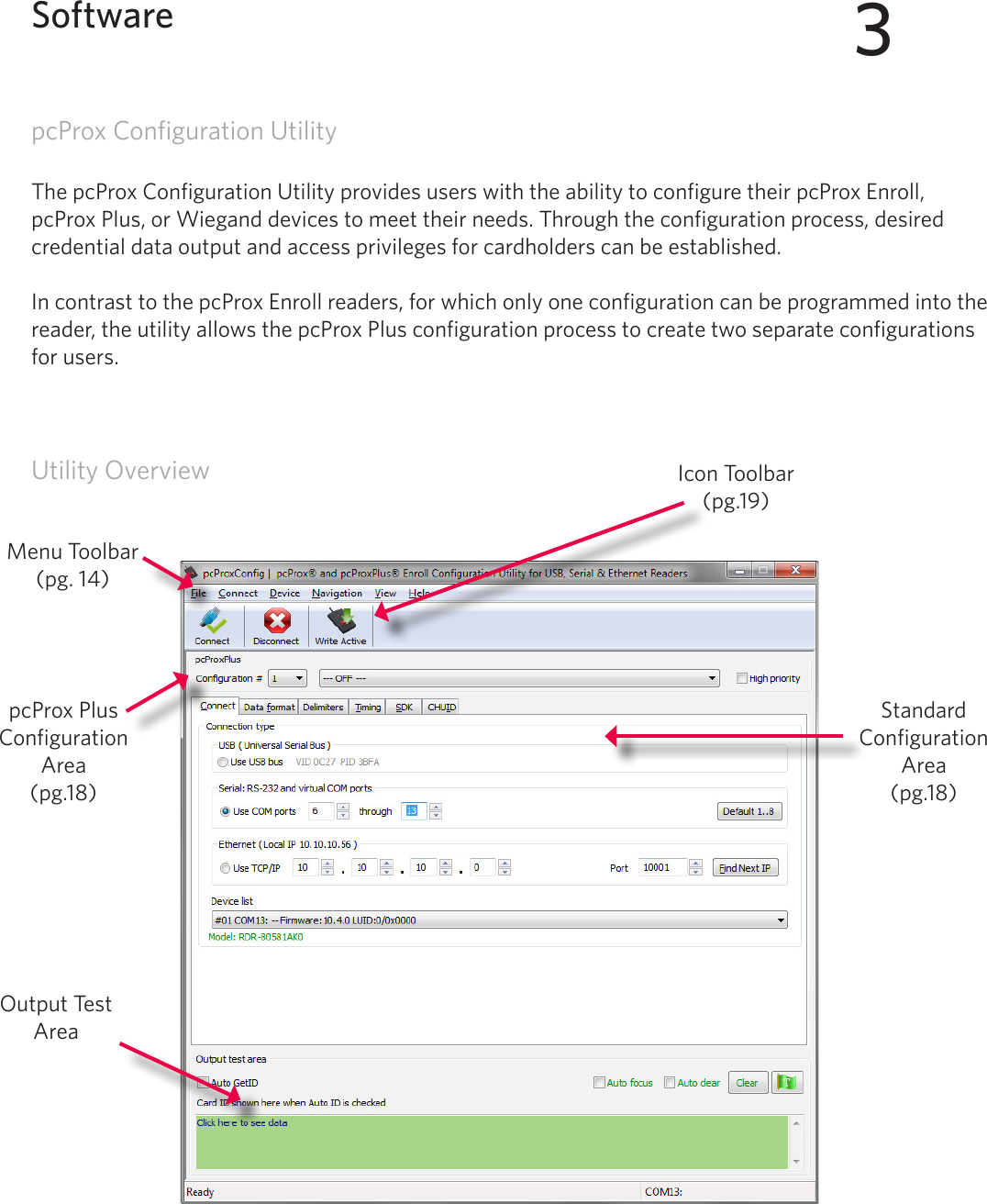
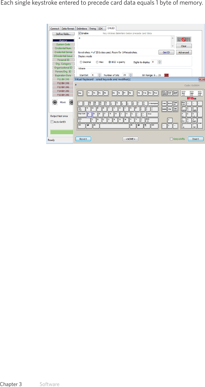
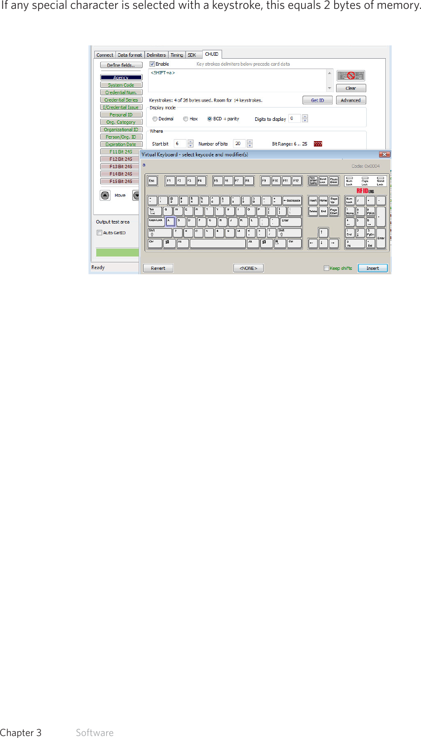
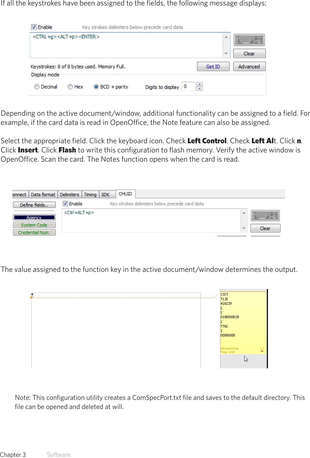
RF Ideas LC60DX RFID Card Reader User Manual

RF Ideas Inc RFID Card Reader Users Manual

Users Manual

99009010 Rev A.2pcProx® Plus, pcProx® Enroll & Wiegand ConverterConfiguration UtilityUser Manual
Thank You!Congratulations on the purchase of your pcProx® Enroll, pcProx® Plus, or Wiegand device(s).            RF IDeas hopes you enjoy using the readers as much as we enjoyed creating and developing them.  Configuration is easy, so you will be able to quickly take advantage of a more secure environment in your business, school, or organization.Please call our Sales department if you have any questions or are interested in our OEM and Independent Developer’s programs.We look forward to your comments and suggestions for our product line!  Please go to www.RFIDeas.com and follow the Support a Learning Center link for more details about our product line.We are always discovering new applications for our product line(s).  There are several software developer’s licensing our technology so the solution you are looking for may already be developed.Thank you,The RF IDeas StaffNeed Assistance?  Ph: 847.870.1723  Fx: 847.483.1129  E:  Sales@RFIDeas.com       TechSupport@RFIDeas.com2
3ASCII: The American Standard Code for Information Interchange codes represent text in computers, communications equipment, and other devices that use text. Contactless: The high frequency 13.56 MHz smart card technology.FAC: Facility Access CodeOEM: The proximity card and badge reader available in self-contained electronic modules for easy system integration.pcProx Contactless: The registered RF IDeas brand name given to all 13.56 MHz contactless card reader products. pcProx Proximity: The registered RF IDeas brand name given to all 125 kHz proximity reader      products. Proximity: The low frequency 125 kHz RFID technology. SDK: Software Developer’s Kit. Software Developer’s Kits from RF IDeas provide the high level command capabilities to integrate software applications to our devices.Glossary Of Terms
4Contents2  Thank You! 3  Glossary Of Terms5  Chapter 1: The Basics 5  Wireless Identification Overview6  ID Card Reader System6  pcProx Output Formats 7  Credential Form Factors8  Card Compatibility8  Reader Configuration Purposes8  pcProx Plus & Non-Plus Reader Differences9  Chapter 2:Hardware 9  What’s In Your Part Number? 10  Interface (Connectors)11  USB Readers and Wiegand Converters 11  RS-232 Readers and Converters11  Minimum System Requirements12  Reader Set-Up Basics12  LED Beeper13  Chapter 3: Software13  pcProx Configuration Utility13   Utility Overview 14   Menu Tool bar 19  Icon Tool bar22  pcProx Plus Configuration23  Standard Configuration 23  Connect Tab25  Output Test Area26  Data Format Tab28  Delimeters Tab30  Timing Tab31  SDK Tab35  CHUID Tab45  Chapter 4: ASCII Command Protocol45  ASCII Overview46  Connect Serial Communications Program47  Command Structure50  Help Command54  Variable Command58  ACP Error Codes59  Chapter 5: Tips and Troubleshooting59 Troubleshooting60  Frequently Asked Questions63 Precautions63  Before You Call Technical Support63  Talking To The Technician   66  Index67  Appendix 69  Other Products and Accessories
5Wireless Identification OverviewpcProx® Activated IdentificationEmployers are more security conscious than ever.  More buildings, machines, systems, and applications require identification information to gain access.  RF IDeas devices allow the building access cards to be used as a digital identifier throughout the workplace.Various pcProx applications include:• Card Enrollment• Application log-on• Form filler to existing software applications• PC/LAN Log On• Cafeteria Purchases/Vending• Machine Access• PLC and embedded controllers• Time/AttendanceOur pcProx Plus devices are easily configured to increase security and reliability.  Companies using proximity and/or contactless technology for building access immediately benefit, as their employee identification cards can also be used with the proximity/contactless device for additional authentication applications.  Thus, the majority of deployment and enrollment costs are quickly recovered.The diagram on the following page is a high level overview of how the reader works.  The reader sends RF signals to the card and the card sends signals back to send data.  The card data is output by the reader in keystrokes or ASCII characters. This card data can be configured to include delimiters to separate the data.  This reader can be used as a standalone system or seamlessly integrated with other software applications using the optional Software Developer’s Kit (SDK).1The Basics
ID Card Reader SystemOutput Formats6   Chapter 1   The Basics
7  Chapter 1   The BasicsCredential Form FactorsCredentials are inactive electronic devices that rely on readers to supply the required power for start-up and communication. The credential itself, consists of antennas that produce proximity or contactless frequencies. Proximity and contactless smart card technology cards allow users to effortlessly manage multiple applications through a single credential. Data: The data on access cards are a string of binary numbers set with a fixed configuration and length.Frequencies: RF IDeas’ access control readers and credentials utilize the low-frequency 125 kHz (proximity) band and/or the high-frequency 13.56 MHz (contactless) band.Credential Form Factors: With over 300 million physical access credentials in use worldwide, there are a variety of low and high frequency form factors customers can choose from to meet their particular needs.The below illustrates some of the various form factors available.CSN: Also known as the Card Serial Number, is part of the ISO 15693 standard for vicinity cards operating at the 13.56 MHz frequency.UID: The User ID or User Identification, can be encoded as data on the card when a security key is needed.
8  Chapter 1   The BasicsManufacturer/Vendor Card CompatibilityPlease go to www.RFIDeas.com for specific device part numbers associated to card types.Reader Configuration PurposesThe method of encoding data on a card and transmitting data to the reader differs accordingly to each technology involved.  The reader itself is not aware of the makeup of the card data format or access privileges for the cardholder. This information is only accessible through the configuration process of the reader utilizing the supplied software.The reader is very flexible and may need to be configured in order to present an exact desired output for the user, such as, singling out FAC or ID, obtaining a desired base (i.e. decimal, lowercase, upper-case, hexadecimal).Differences Between pcProx Plus Reader Non-Plus ReaderThe pcProx Plus is a dual frequency programmable reader that combines 125 kHz and 13.56 MHz technologies into the same reader. It’s the only reader in the industry that reads two cards of your choice among 35 card types, delivering flexibility to any customer struggling with different card technologies. In contrast to the pcProx Plus reader, our standard pcProx Enroll proximity and contactless readers function on a single frequency band, which is either 125 kHz proximity or 13.56 MHz contactless.
9What’s In Your Part Number?All RF IDeas reader part numbers follow a distinct system of categorization to allow for an ease of differentiation between products. Below is the basic part number scheme.  RDR    -   6  3  8  1   A  K  U                            Reader Type: The reader type distinguishes between standard reader, OEM, converter, mag-stripe, or a kit.Frequency: RF IDeas’ access control readers are available in low-frequency 125 kHz (proximity) or high-frequency 13.56 MHz (contactless).Card Type: The card type allows for the selection of over 35 different card types for reader compatibility (Please visit www.RFIDeas.com, choose a product and locate the Part Numbers tab for specific device part numbers associated to card types). Housing: This option provides the user to select the form factor housing for the desired reader. The housings include; desktop, wall mount, USB dongle, PCMCIA, bare board, ExpressCard, or custom. (For more on form factors, please visit www.RFIDeas.com)Model: The model selection corresponds to the type of reader, whether it is a standard, writer (13.56 MHz contactless only), playback (13.56 MHz contactless only), SDK, or analyzer.  Version: The version refers to the selection of either our standard or custom build.Housing Color: The color category simply allows for the selection of either our black or pearl housings. (Applies only to desktop and wall mount housings)Interface: This option specifies the type of connection for the reader (i.e. USB, RS-232, PCMCIA, etc).2HardwareReader Type Frequency Card TypeHousingModelVersionHousing Color Interface
10  Chapter 2   HardwareInterface (Connectors) OUTPUTCONNECTORST
11  Chapter 2   HardwareUSB Readers and Wiegand ConvertersThe pcProx USB keystroke device operates in two primary modes:• USB keyboard.  It reads the card data and sends it as keystrokes as if the user typed the ID data on a keyboard.• Under the application programmer interface (API) defined in the pcProx SDK. When it reads card data, the active application receives the entire card data.Note: The pcProx ExpressCard operates as a USB reader. RS-232 Readers and ConvertersThe RS-232, Ethernet, or virtual COM port device operates in two primary modes:  1. ASCII output device.  In this mode the user card data is read and sent as a decimal or hexadecimal number in ASCII characters.2. API defined in the pcProx SDK.  The device attaches to a computer serial port.  When it reads card data, the active application receives the entire card data.Once the configuration settings are correctly configured and written to flash memory, the device can immediately be deployed.Note: The pcProx PCMCIA operates as an RS-232 reader.Minimum System RequirementsMinimum System Requirements HARDWARE       Pentium class PC MEMORY       32 MB RAM DISK         25 MB hard disk space I/O         1 available RS-232 or USB Port Operating System     Any operating system that supports  a USB keyboard including                       Microsoft Windows 2000®, XP®, Vista®, 7®, Server 2003®,            Server 2008®, Linux, Macintosh®.  Can be used for keystroke        applicationsNote:  The software does not perform any data validation checking.  The data must be known before it is read to verify its validity.
12  Chapter 2   HardwareReader Set-Up BasicsPlug the connector into the workstation’s (or available on any peripheral) open RS-232, USB or Ethernet plug.Place the device next to the monitor, beside the workstation, or where appropriate. The workstation should detect new hardware for USB connections.  Verify the workstation recognizes this connection using Device Manager’.Verify the correct COM port for RS-232 DB9 connections using ‘Device Manager.’ When the software is installed, it should recognize these connections in order to configure the appropriate device.  Once the device is configured and written to its flash memory, these settings will not have to be configured again.LED BeeperThe desktop, USB dongle, wall mount, and bare board (OEM) model readers are all equipped with a light up LED on the front cover. The LED is configurable through the utility software (See LED and Beeper functions in the Software section) to allow the device to produce a beep upon light up of the LED when a credential is detected by the reader.
13pcProx Configuration UtilityThe pcProx Configuration Utility provides users with the ability to configure their pcProx Enroll, pcProx Plus, or Wiegand devices to meet their needs. Through the configuration process, desired credential data output and access privileges for cardholders can be established. In contrast to the pcProx Enroll readers, for which only one configuration can be programmed into the reader, the utility allows the pcProx Plus configuration process to create two separate configurations for users. Utility Overview3SoftwareOutput Test AreaIcon Toolbar (pg.19)Menu Toolbar(pg. 14)pcProx Plus Configuration Area(pg.18)Standard Configuration Area (pg.18)
14  Chapter 3   SoftwareMenu Tool BarThe Menu Tool Bar contains all the basic configuration options for the utility.  FileThe file menu lists the options for Opening .Hwg and Saving .Hwg files. Open .Hwg/.Hwg+ File: Opens either a .Hwg or .Hwg+ file.  A .Hwg or .Hwg+ file contains all the configuration settings for the reader. The utility comes with sample .Hwg/.Hwg+ files.Save to .Hwg+ File: Saves the configuration settings to the reader. What is a .Hwg/.Hwg+ file? There are two kinds of configuration files. There is a .Hwg file and .Hwg+ file. A .Hwg file can only be created with previous pcProx application utility ver-sion. A .Hwg+ file can only be saved using this new utility . A .Hwg+ can configure a pcProx Plus reader as well as a single configuration reader.Exit: Exits out of the entire utilityConnectThe connect menu provides options for device to utility connections.Auto Connect to USB on Startup: Set as utility default connection. Through this connection the utility searches for a USB connection on startup.Auto Connect to Serial on Startup: With this selection, the utility searches for any available serial connections on startup.Auto Connect to Ethernet on Startup:  Utility option to search for ethernet connections on startup.Why use the Auto Connect feature? The utlity’s auto connect features allow users to have an easy auto connect through a specified port on startup.Connect: This selection has the utility search for a device connection through all available port connections.Why use the Connect feature? The utlity’s general connect option gives users the ability to connect their device to the utility, without the user needing to identify the devices actual interface connection. This feature cycles through all available ports until a device is found.Note: For further information on the connect option, see the connect portion of the Icon Toolbar section on page 19 of this manual.
(Connect--Cont.)Connect to USB: Connects to current specified reader through USBConnect to Serial: Connects to current specified reader through serialConnect to Ethernet TCP/IP: Connects to current specified reader through ethernet TCP/IPWhy use the Connect to feature? The connect to feature allows the utility to connect to a device through the specified port upon selection. This is especially helpful when users are switching out and changing devices with different connections.Disconnect: Disconnects all connected devices from every available interface connection from the configuration utility. Note: For further information on the disconnect option, see the disconnect portion of the Icon Toolbar section on page 21 of this manual.Device MenuThe device menu lists the options for resetting, writing to, and reading the device’s data memory. The  device menu options are altered depending on the type of device that is connected.  A single configuration reader device has different device menu options than a two configuration reader device.Single Configuration Readers:Reset to Factory Defaults: Resets all configuration parameters to factory defaults.Read Settings: Displays the current connected device configurationWrite Settings: Writes the current configuration settings to the connected device Note: For more information on the Write Settings option, see the Write Settings/Write Active portion of the Icon Toolbar section on page 21 of this manual.pcProx Plus - 2 Configuration Reader:Reset to Defaults: Resets all configuration parameters to defaults. Defaults are set as HID Prox and RDR-758x Equivalent (covers 5 different card types; HID iCLASS CSN, ISO 14443A CSN, ISO 15693A CSN, MIFARE CSN, MIFARE DESFire CSN)Reset to Stored Settings: This selection allows users to reset the device to their own personally defined stored settings. Write Stored Settings: writes the current configuration settings to stored settings Note: Stored settings are defined as configuration settings created by a user and set/written to the device through the utility as a stored settings.15  Chapter 3   Software
16  Chapter 3   Software(Device Menu--Cont.)pcProx Plus - 2 Configuration Reader:Read Active: Reads the current configuration. Active settings are what allow the device to function. Write Active: Writes the current configuration to active settings. Note: For more information on the Write Active option, see the Write Settings/Write Active portion of the Icon Toolbar section on page 21 of this manual.Note: Device Menu options are altered when a two configuration device (pcProx Plus) is connected to the utility.Navigation MenuThe Navigation menu gives users the ability to navigate in and out of the utility tabs through the use of hot keys. This menu lists the hot key commands for the tabs as seen on the Standard Configuration Area  (An explanation of each tab can be found in the Standard Configuration Area section of this manual). For example, pressing the F5 key on the keyboard will open the Data Format tab.A Test App hot key command is also available in this list. This command opens any keystroking capturing program (i.e. notepad, wordpad etc) in a new window. The Test App default opening program is set as notepad.View MenuThe view menu provides options for altering the appearance of certain functions of the application utility. All the options in this menu are set to appear by default. Show Tooltip Balloon: Menu option for displaying or not displaying the tooltip pop-up balloon. Note: Tooltip balloons appear automatically, or pop up, when the user pauses the mouse pointer over a tool or some other UI element. The tooltip appears near the pointer and disappears when the user moves the pointer away from the tool, or simply waits for a few seconds. The tooltip displays descriptive information of the specific element or tool that the mouse is currently hovering over.
17  Chapter 3   Software(View Menu--Cont.)Show Text Under Toolbar Icons: Provides option to display or remove text under icons in the Icon Toolbar (For more information on the Icon Toolbar, see the Icon Toolbar section on page 19 of this manual).Show Pop-Up Warning Dialogues: Gives option for user to display or remove warning pop-up dialogue boxes. For example, if the Show Pop-Up Warning Dialogues option is selected, then a warning dialogue box, as seen below, will display on your screen. The below warning dialogue box has been displayed  to alert the user that the utility has not detected a connected device.Show Confirm Dialogue: Menu option for displaying yes/no confirmation dialogues before certain utility operations are completed.  For example, if the Show Confirm Dialogue option is selected, a confirmation dialogue window will appear when a user clicks to reset their device to factory defaults. Note: If the Show Confirm Dialogue option is not selected, all utility operations will continue upon user selection without the need for confirmation. Beep On Warnings: Provides an audible system beep when warning are detected. Note: With the Beep on Warnings option, the audible beeps will sound even if the Show Pop-Up Warning Dialogues option is not  selected. Resize Window: The utility window is designed for users to optionally resize, by making the window larger or smaller (the smallest resize choice will eliminate the view of the Output Test Area). If a user resizes the utility window, clicking this Resize Window option will resize the window to its original size.
18  Chapter 3   SoftwareHelp MenuThe help menu provides options for which users can seek out additional assistance using the utility and/or device. Read User Manual: Opens the pdf user manual that is bundled in the download with the configuration utility. Note: The user manual can also be found in the directory folder in which the configuration utility was installed.  www.RFIDeas.com: This operation will open a new window to the RF IDeas website.Check Website for Software Updates: Clicking this option will take users to a location on the RF IDeas software updates portion of the website, and will detect what version of the pcProxConfig utility is currently in use. Any updates that are available will be listed for easy userdownload.About: This selection’s menu options differ when a device is connected to the utility vs. when  there is no device connected. Without a connected device the about informational content simply  displays the utility version. When a device is connected, the firmware information is also provided. The RF IDeas Tech support email and website address are displayed in both modes.
19  Chapter 3   SoftwareIcon Tool BarThe Icon Tool Bar contains the three most general configuration controls for the utility. These controls are also found in the Menu Toolbar under Connect  (for connect and disconnect) and Device (for write settings and write active). ConnectClicking the Connect icon button commands the utility to search for a device through all available port connections. Once the utility detects a device connection, the Device List pull-down menu in the Standard Configuration Area displays the interface connection, firmware and LUID information for the con-nected device. The model number of the device will be displayed below the Device List pull-down and the Output Test Area will turn from gray to green.Note: More than one device can be connected simultaneously to the utility. To switch between devices, select the desired connected device from the Device List pull-down menu. Device List Pull-down MenuDevice Model Number
20  Chapter 3   Software(Connect--Cont.)If an attempt to connect to a device is made and the utility does not detect a device through any of the available interface connections, a “no devices found” message will display in the utility’s status bar area.Status Bar
21  Chapter 3   SoftwareDisconnectClicking the disconnect icon button commands the utility to disconnect from all devices connected  through any and all available port connections. Once the utility disconnects from all available device connections, the Device List pull-down menu and device model number are cleared from the Standard Configuration Area and the Output Test Area will turn from green to gray. Additionally, the status bar will display a “Disconnected” message.Write Settings/Write ActiveThe Write Settings icon button prompts the utility to write the current defined configuration settings to the device. Since the writing options differ between a single configuration device and a two configuration device (pcProx Plus), the Write Settings icon will change depending on whether a single or two configuration device is connected. When a two configuration device is connected, the icon text will change to read “Write Active,” as seen below. Status Bar Message
22  Chapter 3   SoftwarepcProx Plus ConfigurationThis section is only available to configure selections when a two configuration device (pcProx Plus) is connected to the utility. Note: When a single configuration device is connected to the utility, the pcProx Plus Configuration  area is grayed out (as seen below) and selections within this area are not possible.The pcProx Plus Configuration area allows for users to set-up two different configurations for their device. The configurations could be either one 125 kHz and one 13.56 MHz, or two 125 kHz and two 13.56 MHz. The configurations can also be of the same card type. The device is set with two default configuration settings, the HID Prox and RDR-758x Equivalent (covers 5 different card types; HID iCLASS CSN, ISO 14443A CSN, ISO 15693A CSN, MIFARE CSN, MIFARE DESFire CSN). Note: If configuring the system for HID 26 bit and HID 35 bit, remember to set one configuration to read only 26 bits and the other configuration to read only 35 bits. Configuration # (Number): This option provides the ability to switch between configurations. Users can set and edit settings for two separate configurations quickly and easily.Card Type Drop-Down Menu: As stated above, the device is set with two default configuration settings, the HID Prox and RDR-758x Equivalent. This drop-down menu lets users choose the desired card type for their own configuration settings. Each configuration has the ability to have separate card types. High Priority: Provides a pcProx Plus user the ability to give a certain configuration a higher                  priority  than  another.  This  is  useful  when  the  user  has  a  population  of  cards  consisting  of  a                                                                                                               combination of 13.56MHz/125kHz cards as well as single-technology cards, and one of those is preferred over the other.  The High Priority bit increases the time it takes to read the card. When the High priority bit is set, the reader will try to read that card type 10 times before switching to the other configuration. Configuration # (Number)Card Type Drop-DownHigh Priority
23  Chapter 3   SoftwareStandard ConfigurationThis Standard Configuration area provides all the options and details necessary to configure a connected device. Connect TabThe connect tab offers the various ways a device can connect to the configuration utility. The different selections allow the user to choose the connection type for the specific logical protocol of their reader.Note: Only one connection type at a time will be shown.USB: Make this selection if the connected device has a USB logical protocol. The utility will then proceed to scan any available USB bus for connected devices.Serial: RS-232 and Virtual COM Ports: This option provides devices that are RS-232 or Virtual COM port logical protocols to connect to the utility. This section scans for RS-232, physical COM port devices, virtual COM port devices, including USB, CDC and PCMCIA devices.When making this selection, the lower and upper limits of the COM ports to scan need to be set. The port values range from 1 to 256. The default COM ports are set at 1 thru 8. Default 1..8: This option sets the COM port values back to the default of 1 and 8. Note: Serial devices may slow when scanning a wide port range.USBEthernetSerial: RS-232 and Virtual COM
24  Chapter 3   Software(Connect Tab--Cont.)Ethernet (Local IP 10.10.10.65): Connects to an Ethernet reader at the given IP address and open a TCP/IP on the given port. The first, second, third, and fourth byte of the TCP/IP address need to be entered for the interface to connect to the reader. The IP port number will also be required. Port Option: Allows for changing the port location. Xport port location needs to match this number Note: Ports below 1024 are for system use only.Find Next IP Button: Looks for other readers on the same ethernet connection.Device List Pull-down: Lists the devices that the utility is actively connected to.For Example, if you have an RJ45 connector (as seen below) then the specific logical protocol connection to be selected is Ethernet. Note: Remember, not all USB interface connections do not necessarily logically connect through USB. If your device has a USB connector, and your device part number suffix is xx0 or xxF, the logical protocol connection is made through COM. A device with a  USB interface connector and a part number suffix of xxU will connect through the USB connect option.CONNECTORS
25  Chapter 3   SoftwareOutput Test AreaThis is the test area for the keystrokes entered by the reader. On serial devices this displays the unsolicited serial port data.The Auto GetID box can be checked for the utility to poll the reader for a card ID every 500msec and displays the results directly under the checkbox, as seen below.The Auto Focus box keeps the cursor in the test area box to capture the keystrokes output by the device. Note: When the Auto Focus box is checked, it is possible that the selection may conflict with the menus and drop downs, due to the fact that the cursor will attempt to move back into the test area.  If this problem arises, simply uncheck the box. The Auto Clear box auto selects all text in the Output Test Area, so that new keystrokes output by the device will replace old text.The Clear button erases all text in the Output Test Area each time the user manually presses the clear button. The Test button (Green Flag) starts the batch file “testarea.bat” or script “testarea” to bring up a users own application to view the readers keystrokes. It opens any keystroking capturing program (i.e. notepad, wordpad etc).Card DataAuto GetID Auto FocusClearTest ButtonAuto Clear
26  Chapter 3   SoftwareStatus BarThe status bar (below the Test Area) displays various messages to alert the user of what the utility is doing, as well as connections and disconnections between the utility a device.Data Format TabThis tab provides users the ability to format how the data on a card will be keystroked out by the utility.The above diagram illustrates the various characters that can be displayed upon a card detection by a connected device. The number portions of the diagram are values that are displayed from a card. The letter portions of the character diagram are values that are formatted by the user through the utility and are keystroked from the device.Status BarABC = Pre-Card ID Delimeters- 3 Characters Max123 = Facility Access Code (FAC)987654321 = Card ID ValueXYZ = Post Card ID Delimeters (Shared with Pre-Card ID)GN = Card Gone Characters (When card leaves fields)T = Termination Character
27  Chapter 3   SoftwareWiegand to Keystroke Data FormatStrip Leading and Trailing Bit Count: By altering the numbers in the leading and trailing bit count, users have the option to strip and discard bits from the card data. The leading and trailing bit counts can be set to range from 0 to 15.Send FAC: (Facility Access Code) Allows for option to display the FAC codeSend FAC as Hexadecimal Number: Will send FAC as a hex number. The default is set to output as a decimal.Send ID: This selection keystrokes out the ID portion of the card data. Note:  When checked uses the defined ID field bit count bits. When unchecked uses all non parity bits.Send ID as Hexadecimal Number: Will send ID as a hex number. The default is set to output as a decimal.ID Field Bit Count: Sets the number of bits in the ID field from 0 to 80 Fix length FAC/ ID Fields: This option will make the FAC and ID a fixed length FAC Digits: This will alter the FAC output by forcing a set length of digits, between 0 to 32, to be displayed.ID Digits: This will alter the ID output by forcing a set length of digits, between 0 to 32, to be displayed.Advanced SettingsOnly Read Cards With This Bit Count: Select this option to filter out cards that are not the specified bit number. The bit number is specified in the box to the right and can range from 2 to 255 bits. Display Hex in Lowercase: Will display hex in lowercase format. Note: The Send FAC as Hexadecimal or Send ID as Hexadecimal must first be selected before this option can be provided. Use Numeric Keypad: Defines which keypad will be used (whether across the top or with keypad)AZERTY Keyboard Shift Lock: This selection will output the data as if it were being output from an AZERTY keyboard.
28  Chapter 3   Software(Data Format Tab--Cont.)FAC Extended Precision Math On: Interprets the FAC data from a card to allow for the proper amount of bits to provide appropriate info.ID Extended Precision Math On: Interprets the ID data from a card to allow for the proper amount of bits to provide appropriate info.Reverse Wiegand Bytes: Reverses data in byte chunks (8 bits = 1 byte)Reverse Wiegand Bits: Reverses each bitInvert Wiegand Bits: Inverts each bitEmulate ProxPro-Append Serial Checksum: This option is only for serial devices. It adds a digit to the end of serial data. It emulates the serial data format to match HID Corp. Prox Pro reader by sending a 2 byte checksum after the card data.Delimiters TabUse this tab to configure pre and post data delimiters. A delimiter can also be set between the ID and FAC card data.Click the appropriate keyboard icon to select the appropriate corresponding delimiters.Note: Only 3 pre and post delimiters total can be configured. If 3 pre-delimiters are set, no post delimiters can be set.Pre Data Delimiters (ABC): Select from 0 to 3 characters to display at the beginning of the card data. These characters are shared with the post string of characters.FAC/ID Delimiter (:): Select a character to display between and separate the FAC and ID data.ABC = Pre-Data : = FAC/ID
29  Chapter 3   Software(Delimiters Tab--Cont.)Post Data Delimiters (XYZ): Select from 0 to 3 characters to keystroke to the end of the card data. These characters are shared with the pre string of characters.Termination Keystroke (T): Adds a keystroke to the end of the card data to signify the end of the card data.Card Gone Delimiters (GN): Adds a keystroke to the end of the card data when the card is removed.Delimeter KeyboardThe Delimter Keyboard is used to select user defined delimeters (keys). Once opened users can:Left Click : To select desired delimter (key) Left Double Click: To select desired key and auto insert (the Insert button will also insert the key).Right Click: Toggles between keeping the left Shift on or off The selected delimter keys will highlight and appear in the top left corner that is initially labeled <NONE>. Once a chosen delimter is inserted, the virtual keyboard will close. Revert: Takes user back to previously inserted delimeter choice <None>: Deletes any selected/inserted delimterInsert: Applies selected delimter to be used Note: Depending on the type of device connected (i.e. serial, FIPS201, etc.), certain keys may be defaulted to highlight upon opening the keyboard. To deselect, simply toggle between your desired delimiter key.Special Keys--Sp1, Sp2, Sp3There are some additional measures that can be taken to make it more difficult for unauthorized users to reproduce passwords, such as, by adding additional keystroke characters to the card information, that is difficult to re-produce, while configuring the data. These additional characters are labeled as Sp1, Sp2, and Sp3 on the delimeters Virtual Keyboard (For more information on Password Security see page 54). The Sp1, Sp2, and Sp3 keys are used only for keystroking environments to send unprintable characters to a specified application.Sp1, Sp2, Sp3 = Special Keys
30  Chapter 3   SoftwareTiming TabUse this tab to configure the device’s card timing and USB keystroke timing.Card Data Hold Time: This option allows for users to determine in msec’s how long they need to wait before the device is able to read the next card in line (which is also how long the LED will remain green after a card read).  The timing options can range from 50 to 9950 min/max (50msec increments only) and the default is set to 1000. Note: This is how long the data is available for the SDK user.Continuous Read, Sends Data Upon Read: When a card is placed on a device, this option will al-low the data to be sent continuously. Lock-Out Time for Repetitive Reads: The time that it takes the reader to read another card.Must be equal to or greater than the hold time and is only done in 50msec increments. Note: For a 2 configuration device (pcProx Plus) the lock-out time is the same as card data hold time. Key Press Time: The length of time the key is held down. The minimum value is 0. The maximum is 640. The default is 20.Key Release Time: Enter the time delay between keystrokes. If set to 0, the reader will output as fast as it can go. The minimum value is 0. The maximum is 640. The default is 20.
31  Chapter 3   SoftwareSDK TabUse this tab to configure the Software Developer’s Kit (SDK) functions, as well as enable and disable keystroking.Software Developers Kit          Function                                                        Description Disable Keystrokes for SDK  Check to disable keystroking. When keystroking or unsolicited   (Halt Keyboard Send)    serial out is disabled, all card data must be read via the SDK       functions.   LEDThe LED section allows users to control the LED light actions on the device to provide users info regarding the card data.Function      Description Auto       Select this to make the device set the LED color. Off     Select this to set the LED to off Red           Select this to set the LED color to red. Green         Select this to set the LED color to green. Amber    Select this to set the color to amber.
32  Chapter 3   SoftwareLogical Unit ID: A user defined 16 bit Logic Unit ID to identify one device from another. BeeperFunction      Description Enable Beep on Card Read       Check this to set the device to beep when a card is read. Beep Now          Press to listen to the beep the reader will provide when in        use.  Long Beep(s)         Check the box to configure a long beep of 375 msec. By              default the beep is set to a short beep of 125 msec. 2 long              beeps or 5 short beeps are allowed onlyThe number value input area to the right of the Long Beep(s) box is designated for the number of beeps to produce when the device is in use.OEM Converter BoardFunction      Description Beeper On (Output Active Low)    Check this to turn the device beeper on. Relay On          Check this to activate the OEM board.
33  Chapter 3   SoftwareCard ID       Function           Description GETID     Click while scanning a card over the device. The ID displays under the      button. This returns 64 bits maximum. GETID (32)     Click while scanning a card over the device. The ID displays under the      button. This returns 255 bits maximum. GetQueuedID   Click to display the last card data read. This returns 255 bits maximum. Clear Lockout   Check to clear the time remaining to allow the device to read the next   card immediately. Clear UID     If clearUID is set, the card and the over run counters will be cleared for   the next read.      If clearHold is set, the reader will be ready to read another card   immediately.GETID Data DisplayThe Most Significant Byte is first – 79.The Least Significant Byte is last – A1.GETID(32) Data Display
34  Chapter 3   SoftwareGetQueuedID Data DisplayHH:MM:SS displays – 00:00:06
35  Chapter 3   SoftwareCHUID TabThis tab allows manipulation of all fields on the Federal Information Processing Standard (FIPS) 201,or proximity cards. Use the red buttons to configure additional fields. The fields can be moved to change the order displayed in the binary bit pattern display.Function      Description Define Fields             Click to select the number of source bits to define the fields. The                           correct type must be selected to allow for all card bits to be manipulated. Enable               Check to enable the highlighted field. This allows the delimiters to be                  output and the corresponding card field to be processed and output. All                  green fields are enabled. All red fields are disabled. Keyboard                   Click to select key delimiters that are stored in the device’s flash memory                  that precede card data output. Each field may have from 0 – 14 key                  strokes.  Clear                Click to clear keystrokes preceding the card data. Decimal               Click to display the card field in decimal format. Hex                 Click to display the card field as a base 16 number in uppercase HEX                 0 – 9 and A – F. BCD w/ Parity              Displays the card data in binary coded decimal, where each 5 bits                 represent 1, 2, 4, 8, and parity. FASCN data is always odd parity.
36  Chapter 3   SoftwareFunction      Description Advanced       Click to display the binary bit pattern. GetID       Click to display the binary bit pattern captured from the card. Start Bit       Enter a number to define the left most significant starting bit for the      field. Bits         Enter the number of bits to add to the Start Bit to define the range of bits      in the field. Digits       This is the number of digits that will display in a selected field. Up         Click to move the highlighted field up one position. Down        Click to move the highlighted field down one position.Advanced ButtonThis displays the bit ranges of the card.Click each field button to display the location of the card binary data. In the example below, thePersonal ID starts at bit 111, is 50 bits long, and is 10 digits. The Bit Range is 111 .. 160 and the cardbit pattern is highlighted. This output format is displayed in binary coded decimal with parity (BCD with Parity). This is the 245 bit configuration. If any additional keystrokes were entered to precede the card data, click Clear to remove them.Note: The message that displays the number of bytes used and how much room for keystrokesabove the Advanced button is determined by the device’s flash memory. In this example theconfiguration is: “Keystrokes: 8 of 32 bytes used. Room for 14 keystrokes.” Every field is 15keystrokes maximum. All fields share 96 bytes.The Bit Range that displays to the left of the binary bit pattern is the Start Bit field total + theBits field total – 1.
37  Chapter 3   SoftwareGet IDClick GetID and scan the card to display the output format of the FIPS 201 and proximity card and the interpretation display of the card data. Click GetID to define the fields to set up the device.In this example, The Agency data starts at bit 11, is 16 bits long, and is 5 digits. The location of theagency data is highlighted in the binary bit pattern. The Bit Range is 6 .. 25.The actual card data displays in blue below the binary bit pattern layout. The interpretation of the card data displays in red in the text field. The card data in blue will always be the same. The card data in red changes based on configuration settings flashed to the device.Note: Click Clear to delete the red card data in the text field. A confirmation message will display.
38  Chapter 3   SoftwareThe Start Bit changes the actual location of the selected field on the binary bit pattern.Note: The ‘????’ that display to the right of the Digits field indicate the BCD parity is incorrect. Verifythe correct field is selected.
39  Chapter 3   SoftwareChange Fields ConfigurationClick on the appropriate field button and uncheck Enable to remove field data from being displayed.In the example below, the Agency, Personal ID, and Expiration Date fields have been removed.Additional function keys display to configure more fields.
40  Chapter 3   SoftwareAssign Preceding KeystrokesIf Enable is checked for a field, specific keystrokes can be assigned to precede card data output.Note: The Scan Code output for the key selected displays above the list of keys.Click Clear to remove all preceding keystrokes as appropriate.
41  Chapter 3   SoftwareEach single keystroke entered to precede card data equals 1 byte of memory.
42  Chapter 3   SoftwareIf any special character is selected with a keystroke, this equals 2 bytes of memory.
43  Chapter 3   SoftwareIf all the keystrokes have been assigned to the fields, the following message displays:Depending on the active document/window, additional functionality can be assigned to a field. Forexample, if the card data is read in OpenOffice, the Note feature can also be assigned.Select the appropriate field. Click the keyboard icon. Check Left Control. Check Left Alt. Click n.Click Insert. Click Flash to write this configuration to flash memory. Verify the active window isOpenOffice. Scan the card. The Notes function opens when the card is read.The value assigned to the function key in the active document/window determines the output.Note: This configuration utility creates a ComSpecPort.txt file and saves to the default directory. Thisfile can be opened and deleted at will.
44  Chapter 3   SoftwareFIPS 201 Card ConfigurationIn order to configure a FIPS 201 card:• Click Advanced to display the card data in the binary bit pattern to determine bit length andformat• Click GetID and present the card to the reader• Define the fields to match the specific output• Configure any additional fields as appropriate• Flash the configuration to memoryThe Advanced button displays:• Start bit location• Number of bits for a specific field• Number of digits for the field• Location of the field within the 245 bit range
45ASCII OverviewASCII Command Protocol (ACP) allows the user to talk directly to the device without a DLL or specialapplication. The serial Prox communicates using ASCII commands. Printable ASCII commands at9600 baud, no parity 1 stop bit, and no echo, can be sent to the device.Note: USB devices that are virtual COM port do not need the baud rate set. The input is buffered bythe device and executed when a carriage return (CR) or line feed line feed (LF) is typed. Theunit then parses the command and performs the operation, and displays the results or errorcode. “\r\nRF IDeas>” where \r represents a CR and \n represents a LF that displays on thecommand line.All commands begin with the prefix rfid: and end with a Return key, CR or LF.Determine the COM PortWindowsUse device manager to display the COM ports. Open the serial COM port. If it is a CDC virtual port,open the newly installed device that was created.LinuxMost Linux distributions include Minicom. Download putty (www.putty.org ) to communicate with the serial device if Minicom is not available.After the USB CDC device is enumerated on the Linux machine a device of either /dev/ttyACM0 or/dev/ttyACM1 is found in the /dev/directory. Minicom users may have to create a symbolic link from/dev/ttyACM0 to /dev/modem using the command ln -s /dev//tty/ACMO /dev/modem orln -s /dev/ttyACM1 /dev/modem.Mac OS XThe /dev/cu.usbmodemfa211 device is found on a Mac OS X . Use putty to communicate with thisdevice.4ASCII Command Protocol
Connect Serial Communications ProgramOpen putty.exe. Click Connection a Serial and set the Speed (baud) to 9600, Data bits to 8, Stopbits to 1, and Parity to None. Flow control is not needed as there is no software or hardwarehandshaking.Click Session.Note: Use Hyper Terminal instead of putty with the XP operating system.46  Chapter 4   ASCII Command Protocol
Highlight the appropriate session. Click Save. Click Apply.Putty opens. Type rfid:help and press Enter. The Help command output displays. The complete listof Help command output is found in this section of the Configuration User Manual.Command StructureCommands are not case sensitive. Characters assigned to variables are case sensitive.· All commands begin with a prefix string followed by one or more token strings with a perioddelimiter character between multiple tokens.· Functions must end with a CR or LF.· Variables can be assigned a value with an equal sign followed by the value or queried with aquestion mark.· Any control characters other than CR, LF, and backspace terminate the command.· The Escape key cancels a command.The general syntax is:PREFIX TOKEN { DELIMITER TOKEN } { { =Value} | {?} }The prefix string is rfid:47  Chapter 4   ASCII Command Protocol
Command structure falls into one of three groups:1. Perform a function.2. Assign a variable.3. Query a variable.Perform a FunctionA function performs an operation that may or may not display any results. A function may not bequeried. An example of a function is to write the variable settings to flash memory usingrfid:cfg.write CR.Certain functions that display a value or series of values display the string between curly braces foreasy parsing. For example, the rfid:qid function output displays:{0x00BB,1,0x0000,80;0x000000801CD1931B2F14}Assign a VariableThere are three types of variables:1. Boolean2. Integer3. CharacterExamples of Boolean Assignmentsrfid:op.beep=0rfid:op.beep=truerfid:op.beep=Falserfid:op.beep=FExamples o f Integer Assignmentrfid:out.led=0003rfid:out.led=3 Note: Some integer values require a 16 bit hexadecimal entry.              For Example: pcProx Plus card types: rfid:cfg.card.type=0xFFFFExamples of Character Assignmentrfid:Delim.Chr.fac=’:’ CRrfid:Delim.Chr.fac=’x3a’ CR48  Chapter 4   ASCII Command Protocol
Query a VariableQuery a single variable to display its current value.· Booleans display as true or false.· Integers display as 0..255 with leading zero suppression.· Characters display as single quoted printable ASCII characters in the range 0x20..0x7E.· Values from 0x00 .. 0x1F and 0x7F..0xFF will be with a leading backslash lowercase x and thetwo digit upper case hex number.· The output of the variable displays between curly braces.For example: RF IDeas>rfid:out.led?   {3}Variables are set and stored in RAM and are lost when the utility is closed. Use the cfg.write functionto write the RAM configuration to flash memory. Use the cfg.read function to read the flash memory.49  Chapter 4   ASCII Command Protocol
Help CommandHelp displays the commands followed by its data type and expected syntax. The table below displaysthe Help command output. The functions display in blue.Help Command Summaryrfid:beep.now     rfid:disp.fac.hex‡  rfid:cfg     rfid:disp.fac.send‡ rfid:cfg.card.hipri    rfid:disp.fac.strip‡ rfid:cfg.card.list (Function)      rfid:disp.hex.lower‡ rfid:cfg.card.type    rfid:disp.id.digitsrfid:cfg.read (Funtion)    rfid:disp.id.hexrfid:cfg.reset (Function)    rfid:help (Funtion)rfid:cfg.write (Function)    rfid:op.beeprfid:chr.1      rfid:op.contrfid:chr.2     rfid:op.sdkrfid:chr.3     rfid:out.ledrfid:chr.count.lead    rfid:qid (Function)rfid:chr.count.trail    rfid:qid.holdrfid:chr.eol     rfid:qid.idrfid:chr.fac     rfid:qid.id.holdrfid:chr.gone.1     rfid:time.holdrfid:chr.gone.2     rfid:var (Function)rfid:cmd.echo     rfid:wieg.id.bitsrfid:cmd.prompt     rfid:wieg.inv.bitsrfid:dev.luid     rfid:wieg.qualrfid:dev.part (Function)    rfid:wieg.qual.bitsrfid:dev.ver (Function)    rfid:wieg.rev.bitsrfid:disp.64bit     rfid:wieg.rev.bytesrfid:disp.fac.64bit    rfid:wieg.strip.lead.bitsrfid:disp.fac.digits    rfid:wieg.strip.trail.bits‡ Applies only to the pcProx PlusCommand Data Type R, W, R/W Definitionrfid:beep.now INT W Sounds the beeper immediately up to 5 short beeps or 2 long beeps.beep.now variables:1 – single short beep2 – two short beeps3 – three short beeps4 – four short beeps5 – five short beeps101 – single long beep102 – two long beeps50  Chapter 4   ASCII Command Protocol
Command Data Type R, W, R/W Definitionrfid:cfg (‡ pcProx Plus only)INT R/W The pcProx Plus reader has multiple configurations. Each configuration has the settings associated with a card type. When a configuration is changed, all other related settings reflect that configuration number.Example: To set configuration #1 to keystroke out the card ID preceded by #1/ the following commands would be entered:rfid:cfg=1fid:char.count.lead=3rfid:char.count.lead=0rfid:char.1=’#’rfid:char.2=’1’rfid:char.3=’/’To then set configuration #2 to precede it’s card ID with #2/ the following commands would be entered:rfid:cfg=2fid:char.count.lead=3rfid:char.count.lead=0rfid:char.1=’#’rfid:char.2=’2’rfid:char.3=’/’rfid:cfg.card.hipri(‡ pcProx Plus only)BOOL R/W Enable priority card read. IF True, current configuration is given priority over the alternate configurationrfid:cfg.card.list(‡ pcProx Plus only)Function View list of supported card types and their hexadecimal entries for the rfid.cfg.card.type command.rfid:cfg.card.type(‡ pcProx Plus only)INT (hex) R/W Verify or Set Card type for current configuration in RAM as 16 bit INT (0x0000..0xFFFF) Note: 0x0000 is offrfid:cfg.read Function Read the flash memory settings in to RAM.rfid:cfg.reset Function Reset the flash memory to the factory defaults.rfid:cfg.write Function Write the variables from RAM in to flash memory.rfid:chr.1 CHAR R/W 1st card data delimiter character (A - Z, 0 - 9, a - z or ASCII \0x00 ….\0x0D) urfid:chr.2 CHAR R/W 2nd card data delimiter character  (A - Z, 0 - 9, a - z or ASCII \0x00 ….\0x0D) urfid:chr.3 CHAR R/W 3rd card data delimiter character  (A - Z, 0 - 9, a - z or ASCII \0x00 ….\0x0D) urfid:chr.count.lead INT R/W Verify or Set the leading character count (0 to 3) u51  Chapter 4   ASCII Command Protocol
Command Data Type R, W, R/W Definitionrfid:chr.count.trail INT R/W Verify or Set the trailing character count (0 to 3) urfid:chr.eol CHAR R/W Verify or set end of line termination character ( A - Z, 0 - 9, a - z or ASCII \0x00 ….\0x0D)rfid:chr.fac CHAR R/W Verify or set  separating character between the facil-ity code and ID data( A - Z, 0 - 9, a - z or ASCII \0x00 ….\0x0D) Ex:  123 ; 456789rfid:chr.gone.1 CHAR R/W 1st character sent when card is removed ( A - Z, 0 - 9, a - z or ASCII \0x00 ….\0x0D)rfid:chr.gone.2 CHAR R/W 2nd character sent when card is removed ( A - Z, 0 - 9, a - z or ASCII \0x00 ….\0x0D)rfid:cmd.echo BOOL R/W IF True, enable echo of user input and use of backspace keyrfid:cmd.prompt BOOL R/W IF True, enable RF IDeas command promptrfid:dev.luid INT (hex) R/W Verify or set the logical unique identifier as 16 bit INT (0x0000..0xFFFF)rfid:dev.part Function Read the device part numberrfid:dev.ver Function Read firmware version (major . minor . variant)rfid:disp.64bit BOOL R/W IF True, use 64 bit math on ID datarfid:disp.fac.64bit BOOL R/W IF True, use 64 bit math on facility code datarfid:disp.fac.digits INT R/W Verify or set Length of facility code output (up to 25 digits)rfid:disp.fac.hex BOOL R/W IF True, enable facility code output as hexrfid:disp.fac.send BOOL R/W Enable output of facility coderfid:disp.fac.strip BOOL R/W Set to True to separate ID and FAC. False processes ID and FAC together.rfid:disp.hex.lower BOOL R/W IF True, hex ID data is output in lowercaserfid:disp.id.digits BOOL R/W Verify or Set ID data length (0 to 25 digits) Note: If value is shorter than actual Id length the left most significant digits will be truncatedrfid:disp.id.hex BOOL R/W IF True, enable ID data output as hexrfid:help Function View menu of commands, summary of output types and variable optionsrfid:op.beep BOOL R/W Beeper output control True=beep, False=silentrfid:op.cont BOOL R/W Continuous read mode True=continuous output, False=single output of credential datarfid:op.sdk BOOL R/W IF True, enable Quiet mode. (IE: Credential data is not displayed)  Note:  data can still be retrieved using function rfid:qid.rfid:out.led INT R/W LED output control  0=off, 1=red, 2=green, 3=Amber (Immediate out w\o write) 255=Automatic control by reader (requires write to flash) red on standby, green when credential is read 52  Chapter 4   ASCII Command Protocol
Command Data Type R, W, R/W Definitionrfid:qid Function Reads current queued ID dataEXAMPLE Output String: {0x1000,2,0x0000,80;0x000000801DD1910B2F04} ---Note the use of commas and semicolons--FORMAT of Output String: {AGE,OVERRUN,LOCKOUT,BITCOUNT;ID}AGE (New: Age (in hex) of last card read as a multiple of 48ms. Value stops at 0xFFFF. Use qid.id function to clear the age counter. As shown: the card was read 4,096 (0x1000 hex) x .048 = 196.608 seconds ago or 3 minutes and 16 seconds.OVERRUN counter (Values: 0 through 255): number of times buffer has been over written with new data without content transfer.LOCKOUT:  Time (in multiples of 48ms) re-maining until another card can be read.BIT COUNT bit length of card data (26 to 255).  As shown: The ID contains 80 bits.ID: Card data in hexadecimal. As shown: Card is 80 bits and is 0x000000801DD1910B2F04.rfid:qid.hold Function Read the card data and reset lockout timer. Once the function is called, a new card can be read immediately after without waiting for the lock out time period to expire.rfid:qid.id Function Reads the card data, clears the age, overrun, and bit count after function is called.rfid:qid.id.hold Function Combined functions of rfid:qid.hold and rfid:qid.idrfid:time.hold INT R/W Verify or set current data hold time setting in multiples of 48ms. (0 - 200) Also controls duration of Green LED during Auto mode.rfid:var Function Outputs current command variables in ram (Similar to a .HWG file.) Output can be cap-tured, edited and written back into the device. Note:  To prevent an input buffer overflow, delay each character by several milliseconds.rfid:wieg.id.bits INT R/W Verify or set card data output bit count (0- 255)rfid:wieg.inv.bits BOOL R/W IF True, Invert card data output bits (1 to 0, 0 to 1)rfid:wieg.qual BOOL R/W IF True, use wiegand qualifier to verify card bit count53  Chapter 4   ASCII Command Protocol
rfid:wieg.qual.bits INT R/W Wiegand Qualifier: Number of bits (0 - 255) card data must have to be acknowledged as a readrfid:wieg.rev.bits BOOL R/W IF True, reverse bits of credential output lsb to msbrfid:wieg.rev.bytes BOOL R/W IF True, reverse the bytes of credential output LSB to MSBrfid:wieg.strip.lead.bits INT R/W Leading parity bit count to be stripped from credential data (options: 0 = none, 1 to 142 bits)rfid:wieg.strip.trail.bits INT R/W Trailing parity bit count to be stripped fromcredential data (options: 0 = none, 1 to 142 bits)Key:R = read only commandW = Write only commandR/W = Command can be read for its current value or written with a new value.   Note: Value changes are stored in RAM till rfid:cfg.write is used to store the value in to Flash.uThese three commands identify the delimiter characters that can display. Three characters may be divided up as pre and/or post delimiters. The rfid:count.lead command identifies how many of the three characters (chr.1 .. chr.3) display before the card data. For example, if rfid:count.lead is set to 1, only one character displays before the card data and chr.2 and chr.3 can be set as post delimiters. Then rfid:count.trail can have a value of 0, 1, or 2. If rfid:count.lead is 2, chr.1 and chr.2 are set as leading delimiters. Then, only chr.3 can be set as a trailing delimiter. However they are used, the same character location cannot be used for both leading and trailing delimiter.Variable CommandThe var command displays all variables. The command output can be captured and played back intothe device. There must be a delay of several milliseconds after each character or the pcProx serialinput buffer overflows.rfid:beep.now     rfid:disp.fac.hex=Falserfid:cfg=1     rfid:disp.fac.send=Falserfid:cfg.card.hipri=True    rfid:disp.fac.strip=Truerfid:cfg.card.type=0xEF04     rfid:disp.hex.lower=rfid:chr.1      rfid:disp.id.digits=0rfid:chr.2     rfid:disp.id.hex=Falserfid:chr.3     rfid:op.beep=Truerfid:chr.count.lead=0    rfid:op.cont=Falserfid:chr.count.trail=0    rfid:op.sdk=Falserfid:chr.eol=’\x0D’    rfid:out.led=255rfid:chr.fac=’\x00’    rfid:time.hold=20 rfid:chr.gone.1=’\x00’    rfid:wieg.id.bits=16rfid:chr.gone.2=’\x00’    rfid:wieg.inv.bits=Truerfid:cmd.echo=True    rfid:wieg.qual=False rfid:cmd.prompt=True    rfid:wieg.qual.bits=26 rfid:dev.luid=0x0000    rfid:wieg.rev.bits=False rfid:disp.64bit=False    rfid:wieg.rev.bytes=False rfid:disp.fac.64bit=False    rfid:wieg.strip.lead.bits=1 rfid:disp.fac.digits=0    rfid:wieg.strip.trail.bits=1 54  Chapter 4   ASCII Command Protocol
These five variables work together to display leading and trailing (pre and post) card data delimiters.1. rfid:chr.1=’\x00’2. rfid:chr.2=’\x00’3. rfid:chr.3=’\x00’4. rfid:chr.count.lead=05. rfid:chr.count.trail=0The first three commands identify the pre delimiter characters that can display. Three characters maybe divided up as pre and/or post delimiters. Count.lead identifies how many of the three characters(chr.1 .. chr.3) display before the card data. For example, if count.lead is set to 1, only one characterdisplays before the card data and chr.2 and chr.3 can be set as post delimiters. Then count.trail canhave a value of 0, 1, or 2. If count.lead is 2, chr.1 and chr.2 are set as leading delimiters. Then onlychr.3 can be set as a trailing delimiter. The same character can not be used for both a leading andtrailing delimiter.rfid:cfg=1The pcProx Plus reader has multiple configurations. Each has the settings associated with a card type. When the configuration is changed, all other related settings reflect that configuration number.Example: To set configuration #1 to keystroke out card ID preceded by #1/  the following would be entered.rfid:cfg=1fid:char.count.lead=3rfid:char.count.lead=0rfid:char.1=’#’rfid:char.2=’1’rfid:char.3=’/’And now set configuration #2 to precede it’s card ID with #2/rfid:cfg=2fid:char.count.lead=3rfid:char.count.lead=0rfid:char.1=’#’rfid:char.2=’2’rfid:char.3=’/’rfid:chr.eol=’\x0D’This command sends the End Of Line (EOL) character at the end of the card data. Typically acarriage return (CR) (0x0D) is used.rfid:chr.fac=’:’This command sets a delimiter between the FAC and card data.rfid:chr.gone.1=’\x0A’ and rfid:chr.gone.2=’@’These commands prompt the device to send the characters ‘x0A’ and ‘@’ when the ID card isremoved if they are not ‘00’.rfid:cmd.echo=TrueThis command echoes user input when true and controls if backspace sends a space, backspace,space to erase the last character typed. If false, it is turned off for computer control. This value canbe written to flash memory using cfg.write. It defaults to true on cfg.reset.55  Chapter 4   ASCII Command Protocol
rfid:cmd.prompt=TrueThis command displays the prompt when true. If false, the prompt does not display. This value can bewritten to flash memory using cfg.write. It defaults to true on cfg.reset.rfid:dev.luid=0x1234This command sets the logical unit ID. A user-defined 2 byte value to identify this unit.rfid:disp.64bit=FalseThis command uses 64 bit math to computer 64 bit decimal digits. This should always be kept on. Iftrue, it uses 64 bit math.rfid:disp.fac.digits=3This command truncates or sets the FAC display leading zero.rfid:disp.fac.hex=FalseThis command sends the FAC code in hex when true. If false, the FAC code is sent in decimal.rfid:disp.fac.send=FalseThis command sends the FAC code if true. If false, the FAC code does not display.rfid:disp.fac.strip=FalseThis command separates the FAC from the card data when true so it can be independently formattedfor display. If false, the FAC code is not separated from the card data.rfid:disp.id.digits=16This command sets the digits so the left most significant digits will be truncated. For example, if thecard data is 1234 and id.digits=3, then only 234 displays. If the card data = 8 formats the displaywidth by truncating digits or adding leading zeros.rfid:disp.id.hex=FalseDisplays the card data as hexadecimal when true. If false, card data displays as a decimal.rfid:op.beep=TrueThis command sets the device to beep on a successful card read when true. If false, the device willnot beep even if the card is successfully read.rfid:op.cont=FalseThis command sets the device to continuously read when true. It tells the device to read the samecard data over and over while the card is on the device. If false, the device only sends card data once.rfid:op.sdk=FalseThis command stops the device from displaying the card data when true, so the qid or SDK API callmust be used to get the card data. When true the device will send the data via keystrokes or serialdepending on device type/model.rfid:out.beep=FalseThis command makes the device beep when true. If false, the device will not beep. This is onlyavailable on OEM converter boards.56  Chapter 4   ASCII Command Protocol
rfid:out.led=255This command sets the variable and also sets the output LED color in RAM. Use cf.write to write thischange to flash memory to persist across power cycles.               LED Value                           Description0                      OFF1                     RED2                  GREEN3                  AMBER4..254                Reserved   255                Controlled by the devicerfid.out.relay= TrueThis command sets the output driver to ON (active low) when true. This is only available on OEMconverter boards.rfid:time.hold=20This command sets how long in 48ms ticks the data is held for the active ID. This also controls howlong the device keeps the LED green in 48 msec ticks. The default time is 20 * 0.048 = 0.960seconds.Note: The qid.hold resets the internal timer this value initializes.rfid:time.lo=24This command sets how long in 48ms ticks the card device has to wait for no card in the RF field tobegin accepting new card data. This prevents the same card data from being read over and over. Ifop.cont is true this value has no effect. The default time is 24 * 0.048 = 1.15 seconds.Note: The qid.hold resets the internal timer this value initializes, so that a new card can be read assoon as the data is transferred to the host computer.rfid:wieg.id.bits=80This command sets byte reversal and also defines the FAC bit size.rfid:wieg.inv.bits=TrueThis command sets all ones to become zero in the Wiegand data. If false, all zeros are set to becomea one.rfid:wieg.qual=FalseThis command sets card reading filter to off. If true, card reading filter is on. This is related to the nextcommand, .qual.bits=80.rfid:wieg.qual.bits=80This command sets the device to read only cards with this many bits. All other size cards are filteredout.57  Chapter 4   ASCII Command Protocol
rfid:wieg.rev.bits=FalseThis command does not reverse all bits. If true, the least significant bits are swapped with the mostsignificant bits.rfid:wieg.rev.bytes=FalseThis command does not reverse all the bytes in the id.bits size field. If true, all bytes are reversed.rfid:wieg.strip.lead.bits=1This command strips 0 .. 15 bits from the most significant bits.rfid:wieg.strip.trail.bits=1This command strips 0 .. 15 bits from the least significant bits.ACP Error CodesACP Errors DescriptionsError#1 Illegal Command. Will return “Try “rfid:help”. Possible Wrong or missing prefix “rfid:”Error#2 Input buffer overrun. Too many characters received without CR or LFError#3 Illegal Operation. - Variable assigned to function or variable used as functionError#4 Range Error. Value assigned to variable exceeds limit (EX: 257 for 255 limit)58  Chapter 4   ASCII Command Protocol
59TroubleshootingIf the device is not working or the following error message displays:1.  Check to be sure the device is plugged into the USB or RS-232 port. When the workstation ison and no card is being read, the LED is red. A valid proximity card causes the LED to turngreen, provided the configuration is not set to only read certain bit lengths.2.  Only one COM port application can own the RS-232 port at a time. Make sure there is notanother COM port application running. This prevents our software from seeing the device.3.  Verify the correct model and the software configuration screen agrees with the deviceattached.4.  Verify the port agrees with the workstation connector.5.   If the device still does not work, unplug it, remove ‘General USB Device’ using Windows‘Control Panel’ a ‘Add/Remove’ Hardware. Then reboot the workstation. When theworkstation boots up, re-attach the device USB and the OS should re-install the Windowsdriver automatically.Change the release time to 1000 on the Timing tab for USB keystrokes to slow down the device.Open Notepad or Word and swipe a card to display the card data to see the actions of any non-printable symbols.If the device does not read the card, contact the card manufacturer/vendor to verify that the card type is compatible with the device model.5Tips and Troubleshooting
Frequently Asked QuestionsWhat types of credentials will your desktop and OEM products work with?Our products work with virtually all 125 kHz proximity and 13.56 MHz contactless cards in theindustry today. The charts below can assist you in determining what RF IDeas products willwork with your particular credential. You can reference the RDR part number on our website toget the name of the particular product or you can simply email us at sales@RFIDeas.com withthe number and we will contact you.Solutions for Identification:Solutions for Integrators: When I present my card to the pcProx Enrollment reader the number displayed is not thenumber printed on my card or the same number my access control system displays, why?Check with your supplier for the card format information, since there are some credentials thatrequire a custom format reader. You may possess one of these types of credentials. The pcProxEnrollment readers may need to be configured to output the required credential number, 60  Chapter 5   Tips and Troubleshooting
i.e. FAC, ID or CSN using the pcProx Enroll Configuration Utility for USB and RS-232 readers. You can download our configuration program free of charge by cutting and pasting this path into you web browser http://www.rfideas.com/Software/pcProxConfig.exe. Once downloaded please review the User’s Manual for configuration instructions. If you have any questions please contact RF IDeas   technical support.What software application can I use to view the ASCII output card data from a RDR-6081AKF orRDR-6081AKE?Since these readers use a virtual COM port, the pcProx Enroll Configuration Utility for USB and        RS-232 readers can be used to configure your reader, copy and paste the following path into your web browser and download to your computer.http://www.rfideas.com/Software/pcProxConfig.exe Once downloaded and installed you canuse it to configure the readers and view the output data. HyperTerminal or ProComm Plus canalso be helpful in viewing card data.What configuration utility do I use to configure the pcProx 125 kHz Enroll, pcProx 13.56 MHz Enroll and Wiegand products?The products above may or may not require configuration depending on the badge or card typeyou are using. If you do need to configure them we have a free download. The ConfigurationUtility for USB and RS-232 readers can be found at http://www.rfideas.com/Software/pcProxConfig.exeWhat configuration utility do I use to configure the RDR-7P71AKx FIPS 201 reader?There is currently a beta version called pcProxPlusConfig-Beta.exe for configuring your FIPS 201reader. Copy and paste the following link into your web browser and the beta version willautomatically begin to download http://www.rfideas.com/Software/pcProxPlusConfig-Beta.exe. Please note that this program is a special utility to configure our FIPS 201/long format devices only.Do you have RFID solutions for long read range?Yes, we have several products that can track a vehicle up to 33 feet and traveling as fast as 120miles per hour. Go to our website at www.RFIDeas.com, and select products and select thelong-range tab for more information.How can I use a proximity card for logon?One of the fastest growing areas in contactless and proximity technology is what is known assingle sign on or SSO for short. We have technology solutions that can assist you in convertingyour current building access badge into a multifunctional badge for use inside the building. The con-version will enable you to log in and out of a computer, punch you into the time clock,61  Chapter 5   Tips and Troubleshooting
control multi functional printers and much more. Contact our sales office at 1-866-439-4884Toll Free to find out more.Can I use your product for tracking meeting registration and training attendance?Yes. Our products can be used to track training attendance and meeting registration. Contactour sales office at 1-866-439-4884 Toll Free to find out more on how our products can be usedfor meeting registration, training attendance and many other applications.Why must I poll the USB card reader?The nature of USB is not event driven per se, it operates on a host/client protocol that during enumeration asks the host to poll at a specific rate. As a keyboard we are polled by the OS every 10msec, the same speed your keyboard and mouse is. We use feature report packets to configure the readers. We also communicate to the DLL API through Feature Reports for HID devices. The AK0 units that are RS-232 or CDC can speak English with using the ASCII COMMAND PROTOCOL such as “rfid:help” in Hyper Terminal or putty. We recommend you poll the units every 250msec for the card id, except for AK0 unit and this with a QueuedID, as the reader will report the age of the card id up to 52 minutes. Without the SDK the units can send unsolicited card id when the card is in the rf field. These appear as USB keystrokes or Serial data for RS-232 and CDC models. Take a look at the pcProx manuals it may help you get a better idea of the AK0 protocol. The HID is a proprietary binary protocol, where as the AK0 units are open protocol.62  Chapter 5   Tips and Troubleshooting
PrecautionsDo not mount the device directly on a metal surface. This could interfere with the RF signal and theoperation of the device.The device may not recognize valid cards in the presence of high RF fields. If current readings areerratic, take the following step:· Move the equipment from any known transmitters nearby.Contact Technical Support at 866.439.4884 for more information.Before You Call Technical SupportPlease make sure you’ve identified your reader model and credential type being used. Have this information ready so that your call will be routed to the correct specialist. For Assistance:  Ph: 847.870.1723 E: TechSupport@RFIDeas.comTalking To The Technician  Provide the reader model and credential type being used to the Technical Support Specialist.  Explain your problem to the specialist.  Be prepared to provide the following information: - Error messages displayed on the computer - What you were doing when the problem occurred - What steps you have taken to resolve the problem, including results from each steps  Listen and follow the steps provided by the specialist. Let the specialist know what happens when you perform the steps. 63  Chapter 5   Tips and Troubleshooting
END-USER LICENSE AGREEMENTLICENSE AGREEMENTEnd-User License Agreement for RF IDeas™ SOFTWARE and HARDWARE - RF IDeas’ pcProx®, Proximity Activated Readers, Software Developer’s Kit, and Proximity Reader DLLs, and Protocol(s). IMPORTANT-READ CAREFULLY: This End-User License Agreement (“EULA”) is a legal agreement between you (either an individual or a single entity) and the manufacturer RF IDeas (“Manufacturer”) with which you acquired the RF IDeas software and hardware product(s) identied above (“PRODUCT”). The PRODUCT includes the RF IDeas reader, computer software, the associated media, any printed materials, and any “on line” or electronic documentation.  The SOFTWARE PORTION OF THE PRODUCT includes the computer software, the associated media, any printed materials, and any “on line” or electronic documentation. By installing, copying or otherwise using the PRODUCT, you agree to be bound by the terms of this EULA. If you do not agree to the terms of this EULA, RF IDeas is unwilling to license the PRODUCT to you. In such event, you may not use or copy the SOFTWARE PORTION OF THE PRODUCT, and you should promptly contact the vendor you obtained this PRODUCT from for instructions on return of the unused product(s) for a refund. The products described in this publication are intended for consumer applications. RF IDeas assumes no liability for the performance of product. RF IDeas products are not suitable for use in life-support applications, biological hazard applications, nuclear control applications, or radioactive areas.  None of these products or components, software or hardware, are intended for applications that provide life support or any critical function necessary for the support of protection of life, property or business interests.  The user assumes responsibility for the use of any of these products in any such application. RF IDeas shall not be liable for losses due to failure of any of these products, or components of these products, beyond the RF IDeas commercial warranty, limited to the original purchase price. SOFTWARE PRODUCT LICENSE  The PRODUCT is protected by copyright laws and international copyright treaties, as well as other intellectual property laws and treaties.  The SOFTWARE PORTION OF THE PRODUCT is licensed, not sold. 1. GRANT OF LICENSE.  This EULA grants you the following rights:  *Software. You may install and use one copy of the SOFTWARE PORTION OF THE PRODUCT on the COMPUTER. *Network Services. If the SOFTWARE PORTION OF THE PRODUCT includes functionality that enables the COMPUTER to act as a network server, any number of computers or workstations may access or otherwise utilize the basic network services of that server.  The basic network services are more fully described in the printed materials accompanying the SOFTWARE PORTION OF THE PRODUCT. *Storage/Network Use. You may also store or install a copy of the computer SOFTWARE PORTION OF THE PRODUCT on the COMPUTER to allow your other computers to use the SOFTWARE PORTION OF THE PRODUCT over an internal network, and distribute the SOFTWARE PORTION OF THE PRODUCT to your other computers over an internal network.1.1 General License Grant RF IDeas grants to an individual, a personal, nonexclusive license to make and use copies of the SOFTWARE PRODUCT for the sole purposes of designing, developing, and testing your software product(s) that are designed to operate in conjunction with any RF IDeas designed proximity reader product. You may install copies of the SOFTWARE PRODUCT on an unlimited number of computers provided that you are the only individual using the SOFTWARE PRODUCT. If you are an entity, RF IDeas grants the right to designate one individual within your organization to have the sole right to use the SOFTWARE PRODUCT in the manner provided above.1.2 Documentation. This EULA grants an individual, a personal, nonexclusive license to make and use an unlimited number of copies of any documentation, provided that such copies shall be used only for personal purposes and are not to be republished or distributed (either in hard copy or electronic form) beyond the user’s premises and with the following exception: you may use documentation identied in the SOFTWARE PRODUCT as the le format specication for RF IDeas’ proximity readers solely in connection with your development of software product(s) or an integrated work or product suite whose components include one or more general purpose software products. 1.3 Storage/Network Use. You may also store or install a copy of the SOFTWARE PRODUCT on a storage device, such as a network server, used only to install or run the SOFTWARE PRODUCT on computers used by a licensed end user in accordance with Section 1.1.  A single license for the SOFTWARE PRODUCT may not be shared or used concurrently by other end users. 1.4 Sample Code. RF IDeas grants you the right to use and modify the source code version of those portions of the SOFTWARE PRODUCT identied as “Samples in the SOFTWARE PRODUCT (“Sample Code”) for the sole purposes to design, develop, and test your software product(s), and to reproduce and distribute the Sample Code, along with any modications thereof, only in object code form.2. DESCRIPTION OF OTHER RIGHTS AND LIMITATIONS. *Limitations on Reverse Engineering, Decompilation and Disassembly.  You may not reverse engineer, decompile, or disassemble the  PRODUCT, except and only to the extent that such activity is expressly permitted by applicable law notwithstanding this limitation *You may not reproduce or otherwise emulate, in whole or in part, any form the protocol(s) dened within this PRODUCT for use without a RF IDeas PRODUCT Redistributable Code. If you are authorized and choose to redistribute Sample Code (“Redistributables”) as described in Section 1.4, you agree to: (a) distribute the Redistributables in object code only in conjunction with and as a part of a software application product developed by you using the PRODUCT accompanying this EULA that adds signicant and primary functionality to the SOFTWARE PRODUCT (“Licensed Product”); (b) not use RF IDeas’ name, logo, or trademarks to market the Licensed Product; (c) include a valid copyright notice on the Licensed Product; (d) indemnify, hold harmless, and defend RF IDeas from and against any claims or lawsuits, including attorney’s fees, that arise or result from the use or distribution of the Licensed Product; (e) otherwise comply with the terms of this EULA; and (g) agree that RF IDeas reserves all rights not expressly granted. You also agree not to permit further distribution of the Redistributables by your end users except: (1) you may permit further redistribution of the Redistributables by your distributors to your end-user customers if your distributors only distribute the Redistributables in conjunction with, and as part of, the Licensed Product and you and your distributors comply with all other terms of this EULA; and (2) in the manner described in Section 1.4.*Separation of Components. The PRODUCT is licensed as a single product.  Its component parts may not be separated for use on more than one computer.*Single COMPUTER. The PRODUCT is licensed with the COMPUTER as a single integrated product.  The PRODUCT may only be used with the COMPUTER. *Rental. You may not rent or lease the PRODUCT without permission from RF IDeas.*Software Transfer. You may permanently transfer all of your rights under this EULA only as part of a sale or transfer of the COMPUTER,provided you retain no copies, you transfer all of the PRODUCT (including all component parts, the media and printed materials, any           upgrades, this EULA and, if applicable, the Certicate(s) of Authenticity), AND the recipient agrees to the terms of this EULA. If thePRODUCT is an upgrade, any transfer must include all prior versions of the PRODUCT.*Termination. Without prejudice to any other rights, RF IDeas may terminate this EULA if you fail to comply with the terms and conditionsof this EULA. In such event, you must destroy all copies of the SOFTWARE PORTION OF THE PRODUCT and all of its component parts.nn3. UPGRADES.  If the SOFTWARE PORTION OF THE PRODUCT is an upgrade from another product, whether from RF IDeas or another supplier, you may use or transfer the PRODUCT only in conjunction with that upgraded product, unless you destroy the upgraded product.  If the SOFTWARE PORTION OF THE PRODUCT is an upgrade of a RF IDeas product, you now may use that upgraded product  only in accordance with this EULA.  If the SOFTWARE PORTION OF THE PRODUCT is an upgrade of a component of a package of software 64
`programs which you licensed as a single product, the SOFTWARE PORTION OF THE PRODUCT may be used and transferred only  as part of that single product package and may not be separated for use on more than one computer.4. OEM COPYRIGHT.  All title and copyrights in and to the PRODUCT (including but not limited to images, photographs, animations, video, audio, music, text and “applets,” incorporated into the PRODUCT), the accompanying printed materials, and any copies of the SOFTWARE PORTION OF THE PRODUCT, are owned by RF IDeas or its suppliers.  The PRODUCT and SOFTWARE PORTION OF THE PRODUCT is protected by copyright laws and international treaty provisions.  You may not copy the printed materials accompanying the PRODUCT.5. DUAL-MEDIA SOFTWARE.  You may receive the SOFTWARE PORTION OF THE PRODUCT in more than one medium. Regardless of the type or size of medium you receive, you may use only one medium that is appropriate for your single computer.  You may not use or install the other medium on another computer.  You may not loan, rent, lease, or otherwise transfer the other medium to another user, except as part of the permanent transfer (as provided above) of the SOFTWARE PORTION OF THE PRODUCT. 6. OEM PRODUCT SUPPORT.  Product support for the product is not provided by RF IDeas or its subsidiaries.  For product support, please refer to the OEM supplies support number provided in the documentation.  Should you have any questions concerning the EULA, or if you desire to contact OEM for any other reason, please refer to the  address provided in the documentation provided.FOR THE LIMITED WARRANTIES AND SPECIAL PROVISIONS PERTAINING TO YOUR PARTICULAR JURISDICTION, PLEASE REFER TO YOUR WARRANTY BOOKLET INCLUDED WITH THIS PACKAGE OR PROVIDED WITH THE SOFTWARE PRODUCT PRINTED MATERIALS. Limited Warranty:  RF IDeas warrants to the original buyer of this product, that the hardware and related disk(s) are free of defects in material and workmanship for a period of one year from date of purchase from RF IDeas or from an authorized RF IDeas dealer.  Should the RF IDeas products fail to be in good working order at any time during the one-year period, RF IDeas will, at its option, repair or replace the product at no additional charge, provided that the product has not been abused, misused, repaired or modied.  This warranty shall be limited to repair or replacement and in no event shall RF IDeas be liable for any loss of prot or any commercial or other damages, including but not limited to special, incidental, consequential or other similar claims. No dealer, distributor, company, or person has been authorized to change or add to the terms of this agreement, and RF IDeas will not be bound by any representation to the contrary.  RF IDeas SPECIFICALLY DISCLAIMS ALL OTHER WARRANTIES, EXPRESSED OR IMPLIED, INCLUDING BUT NOT LIMITED TO IMPLIED WARRANTIES OF MERCHANTABILITY AND FITNESS OF PURPOSE.  Since some states do not allow such exclusion of limitation of incidental or consequential damages for consumer products, check the statute of the state in which your business resides.  This warranty gives you the specic legal rights in addition to any rights that you have under the laws of the state in which your business resides or operates. Returns:  RF IDeas products which require Limited Warranty service during the warranty period shall be delivered to the nearest authorized dealer or sent directly to RF IDeas at the address below with proof of purchase and a Return Materials Authorization  (RMA) Number provided by RF IDeas Technical Support Dept. Replacement parts or complete boards become the property of RF IDeas   If the returned board or unit is sent by mail, the purchaser agrees to pre-pay the shipping charges and insure the board or unit or assume the risk of loss or damage which may occur in transit.  The purchaser is expected to employ a container equivalent to the original packaging. Copyright:  Copyright by RF IDeas 2013.  All rights reserved.  Reproduction or distribution of this document in whole or in part or in any form is prohibited without express written permission from RF IDeas.Trademarks:  All RF IDeas products are trademarks of RF IDeas.  All other product names or names are trademarks or registered trademarks of their respective holders.Applicable Patents: RF IDeas pcProx Plus card readers supporting HID formats retain US Patent No. 5,952,935 and U.S. Patent No. 7,439,862.Disclaimer:  This Reference Guide is printed in the U.S.A.  Any resemblance mentioned in the Reference Guide to persons living or dead, or to actual corporations or products is purely coincidental.  RF IDeas believes that the information contained in this manual is correct. However, RF IDeas does not assume any responsibility for the accuracy of the content of this User Manual, nor for any patent infringements or other rights of third parties. RF IDeas reserves the right to make any modications in either product or the manual without giving prior written notication. FCC Compliance StatementFCC ID: M9MPCPROXHUSB100 (HID USB model)                            FCC ID: M9MBUPCPROXH100 (HID RS-232 model)FCC ID: M9MPCPROXM101 (Indala model)                                        FCC ID: M9MBUPCPROXA100 (AWID) FCC ID: M9MRDR6X8X (Kantech, Indala, Casi-Rusco)                      FCC ID: M9MPCPROXP100 (Pyramid)FCC ID: M9MPCPROXC101 (Casi-Rusco model)                              FCC ID: M9MRDR7P71 (FIPS 201 13.56MHz)FCC ID: M9MRFID1856I100 (MIFARE/iCLASS models)                     FCC ID: M9MRDR7L81 (Legic 13.56MHz)FCC ID: M9MRDR7081 (iCLASS Module based)                              FCC ID: M9MRDR7580 (iCLASS MIFARE and Other 13.56MHz)FCC ID: M9MRDR7581 (iCLASS MIFARE and Other 13.56MHz)      FCC ID: M9MRDR7081AKF (iCLASS MIFARE and Other 13.56MHz)FCC ID: M9MRDR7081AKE (iCLASS MIFARE and Other 13.56MHz)  FCC ID: M9MRDR75DX (iCLASS MIFARE and Other 13.56MHz)FCC ID: M9MRDR8XX8U (Plus combo model)      FCC ID: M9MRDR758X (iCLASS MIFARE and Other 13.56 MHz)FCC ID: M9MRDR8058X (Multi-protocol Combo model)    FCC ID: M9M8058XCCL (Multi-protocol and Contact model)FCC ID: M9M758XCCL (MIFARE and Contact model)    FCC ID: M9M7580CCL (MIFARE and Contact model)FCC ID: M9MRDR80081 (Plus SIO Combo Model)    FCC ID: M9MRDR70EX (13.56MHz Express Model)FCC ID: M9MRDR60DX (125kHz USB Dongle Model)     FCC ID: M9MLC608X (125KHz USB Model)FCC ID: M9MOEM805NX (Multi-protocol Combo model)     FCC ID: M9MSB708X (iCLASS 13.56MHz)FCC ID: M9MSB758X (Mifare 13.56MHz)       FCC ID: M9MSB6X8X (Multi-protocol 125kHz) FCC ID: M9MLC6T8X (132 kHz USB Model)      FCC ID: M9MLC60DX (125 KHz USB Model)“Pursuant to FCC 15.21 of the FCC rules, changes not expressly approved by RF IDeas might cause harmful interference and void the FCC authorization to operate this product.Note:  This device complies with Part 15 of the FCC Rules and Industry Canada license-exempt RSS standard(s). Operation is subject to the following two conditions: (1) This device may not cause harmful interference, and (2) this device must accept any interference received, including interference that may cause undesired operation. This product complies with FCC OET Bulletin 65 radiation exposure limits set forth for an uncontrolled environment.The reader may not recognize value cards in the presence of high RF elds. If the current reading is erratic, the user shall take the following step:  Move the equipment from any known transmitters nearby.  For more information contact Tech Support at 866.439.4884.65
IndexIndex66AACP          45, 58ASCII          3, 5, 11, 45. 49, 51-52, 61-62, 69Assign Preceding Keystrokes          40Auto Clear          25Auto Focus          25Auto GetID          25BBeep          12, 17Beeper          32Bit (26) Format Structure          67      CCard Compatibility          8Card Data Hold Time          30Change Fields Configuration          39Clear Button          25COM          11-12, 23-24, 45, 59, 61 Complex Passwords          68Connectors          10, 24Continuous Read          30         DData Delimiters          28-29Delimter Keyboard          29Device List         19, 21, 24EEmulate Prox Pro          28Ethernet          11-12, 14-15, 23-24ExpressCard          11FFAC          3, 26-29 Factory Defaults          15, 17FIPS 201          37, 44GGETID          25, 33, 36-37, 44GetQueuedID          33-34   HHigh Priority Bit          22.HWG          14IIcon Toolbar          19  Connect          19-20  Disconnect          21  Write Active          21  Write Settings          21ID Digits          27KKey Press Time          30Key Release Time          30LLED          30-31         Lock-Out Time          30Logical Unit ID          32MManufacturer Card Compatibility          (See Card Compatibility)MIFARE          15, 22          Minimum System Requirements          11OOEM          3, 9, 12, 32, 56-57, 60One-Factor Security          68Output Test Area          25 PPassword Security          68     PCMCIA          11pcProx Playback          9, 68-69pcProx Plus (2 Configuration Reader)          5, 8,      13-16, 21-22, 30    RRS-232          9, 11-12, 23, 59, 61-62           SSDK          3, 5, 9, 11, 30-31, 50, 52, 56, 62Serial          7, 11, 14-15, 23, 25, 28-29, 31, 45-46,      54, 56Special Keys  Special1          29  Special2         29  Special3         29Start Bit          36, 38, 44TTermination Keystroke          26, 29Test Button          25Tool Tip Balloon          16Two-Factor Security          68UUSB          11-12, 14-15, 23-24, 29-30, 45, 59, 61-62, 69WWiegand          11, 13, 27-28, 53-54, 57, 61, 67, 69Wiegand Bits          28 Wiegand Bytes          28Wiegand to Keystroke Data          27
AppendixStandard 26 Bit Format StructureThere are several bits constructed together that comprise data sent from the proximity card to thedevice. There are numerous bit formats and lengths for proximity cards. The most popular is a 26 bitcard format. The typical layout for this format is 24 bits of usable information as the first and last areparity bits to ensure data integrity.The 26 bit format consists of 255 possible facility codes. Within each facility code there is a total of65,535 unique card numbers.The standard 26 bit Wiegand format is H10301. It is binary encoded data. The format consists of 2parity bits, 8 bit facility code (F) and 16 bit card number fields (B). This format displays below.PFFFFFFFFBBBBBBBBBBBBBBBBPEXXXXXXXXXXXX..........................XXXXXXXXXXXXOBit CodingP = ParityO = Odd ParityE = Even ParityX = Parity maskF = Facility code, range = 0 to 255B = Card Number, range = 0 to 65,535In general, the 26 bit format is the industry standard format. Primary benefits of this include:• Open format• Convenient to order• Universal access control panel acceptanceThe sale of this format is not limited to any one company yet the range of card numbers available inthis format is limited. There is a potential for card numbers to be duplicated.Please go to www.RFIDeas.com and follow the Support a Learning Center a Proximity CardFormats link for more details. The card manufacturer may also have additional details about the cardformat. 67  Appendix
Use the pcProx Device for Password Security - Complex PasswordsIt is possible with certain limitations, to use the proximity token as a password for an application oroperating system log on. The unique card bit-stream converted to either decimal or hexadecimalbecomes the entire or a portion of the password. Enroll this card data to the password of theoperating system application for the user.Since the proximity token has no read/write memory there is no way go change this or write alphanumeric characters such as a user name to the proximity token. Some examples are shown below. Please see RF IDeas pcProx Playback Starter Kit or call the Sales Department if this capability is needed.Several companies have adopted a policy that requires users to change their password every xxnumber of days to increase security. The PIN is the portion of the password the user changes everyxx number of days. Since the card data is completely numeric, any alpha and upper/lower case letterconstraints are handled in the user supplied PIN.A two-factor authentication system is made up of:1. Card ID data2. Personal Identification Number (PIN)The device may be configured to allow operation under either a one or two-factor authenticationsystem.One-FactorIn a one-factor system, the user simply scans the ID card. The device may be configured to add TABkeystrokes ahead of the data as well as a TAB or ENTER keystroke after the card data.Two-FactorThe two-factor approach is especially useful when insisting on password construction rules or periodic changing of passwords.In a two-factor system, the user may enter the PIN either before or after the card data. If the useradds the PIN before the card data, the device may be configured to append the ENTER keystroke.Pre and Post CharactersThere are some additional measures that can be taken to make it more difficult for unauthorized users to reproduce passwords. Adding additional keystroke characters to the card information, that is difficult to re-produce, while configuring the data. These additional characters are labeled as Sp1, Sp2, and Sp3 on the delimeters tab menu selections.   68  Appendix
69Other Products & AccessoriesSoftware Developer’s KitAllows independent developer’s to use their application to read proximity access badge Read ID data of more than 1 billion cards in the fieldPVC Label Proximity CardCredit card size with paper release liner, 500 cards per boxProximity Cards, Labels, Key FobsComplete selection of various manufacturers proximity cards, labels and key fobs.  Marked with data code and ID number,  available in several Wiegand formatspcProx Read/Write Contactless   Reads and writes directly to the smart cardspcProx Writer and PlaybackDesktop read-only for  iCLASS and NXP and  smart cardspcProx Playback Starter KitPlays back card sector data in ASCII or keystrokespcProx Sonar Presence detector configured as a keyboardPS/2 to USB Power Tap Powers a USB RF IDeas device from a PS/2 portMounting Brackets Further adjust the standard mounting of the device angle
70RF IDeas Inc.© 2013 RF IDeas. All rights reserved. Specifications subject to change without notice. Windows, Macintosh, Solaris, Sun Ray and Linux are trademarks of their respective companies. All other trademarks, service marks and product or service names are property of their respective owners.Mention of third-party products is for informational purposes only and constitutes neither an endorsement nor a recommendation. RF IDeas assumes no responsibility with regard to the performance or use of these products. All understandings, agreements, or warranties, if any, take place directly between the vendors and the prospective users.Please feel free to call, e-mail or visit our web site for a full list of applications, products, configuration options, supported cards and form factor specifications. Our web site includes application videos, support materials, case studies anddetailed information about our product line.Every effort has been made to ensure that the information in this manual is accurate. RF IDeas is not responsible for printing or clerical errors.

Navigation menu