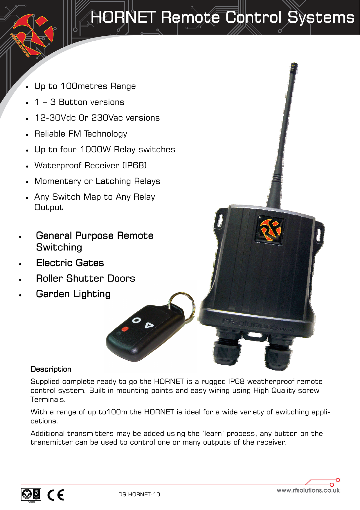
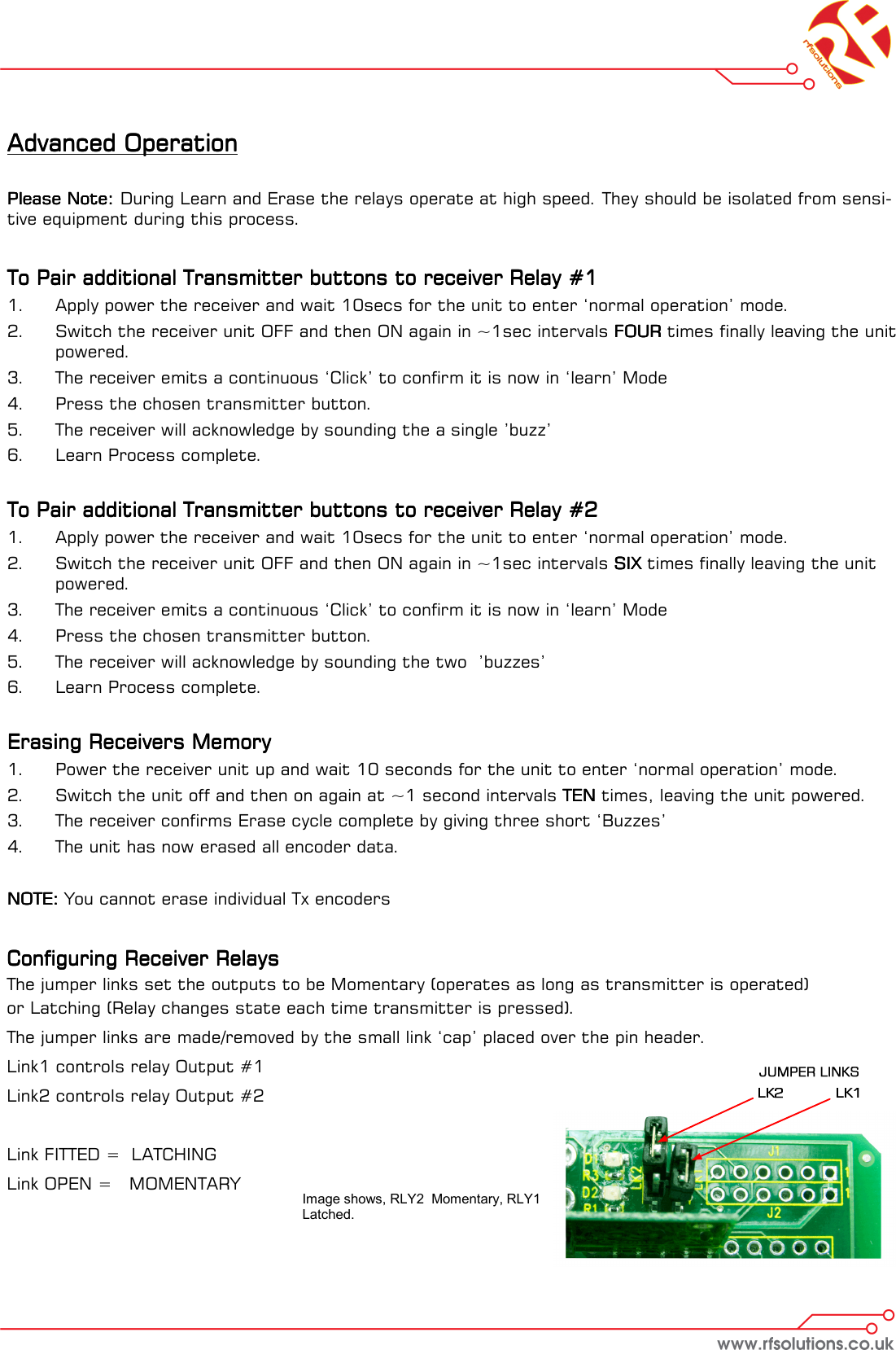
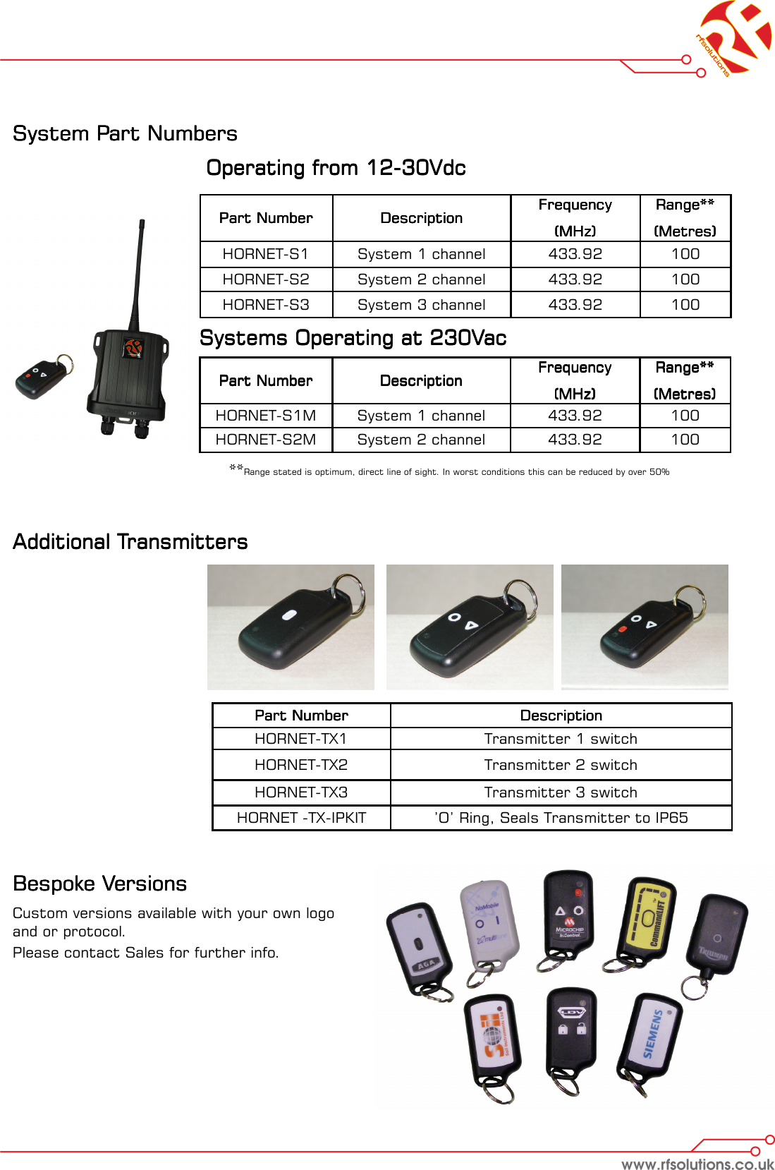
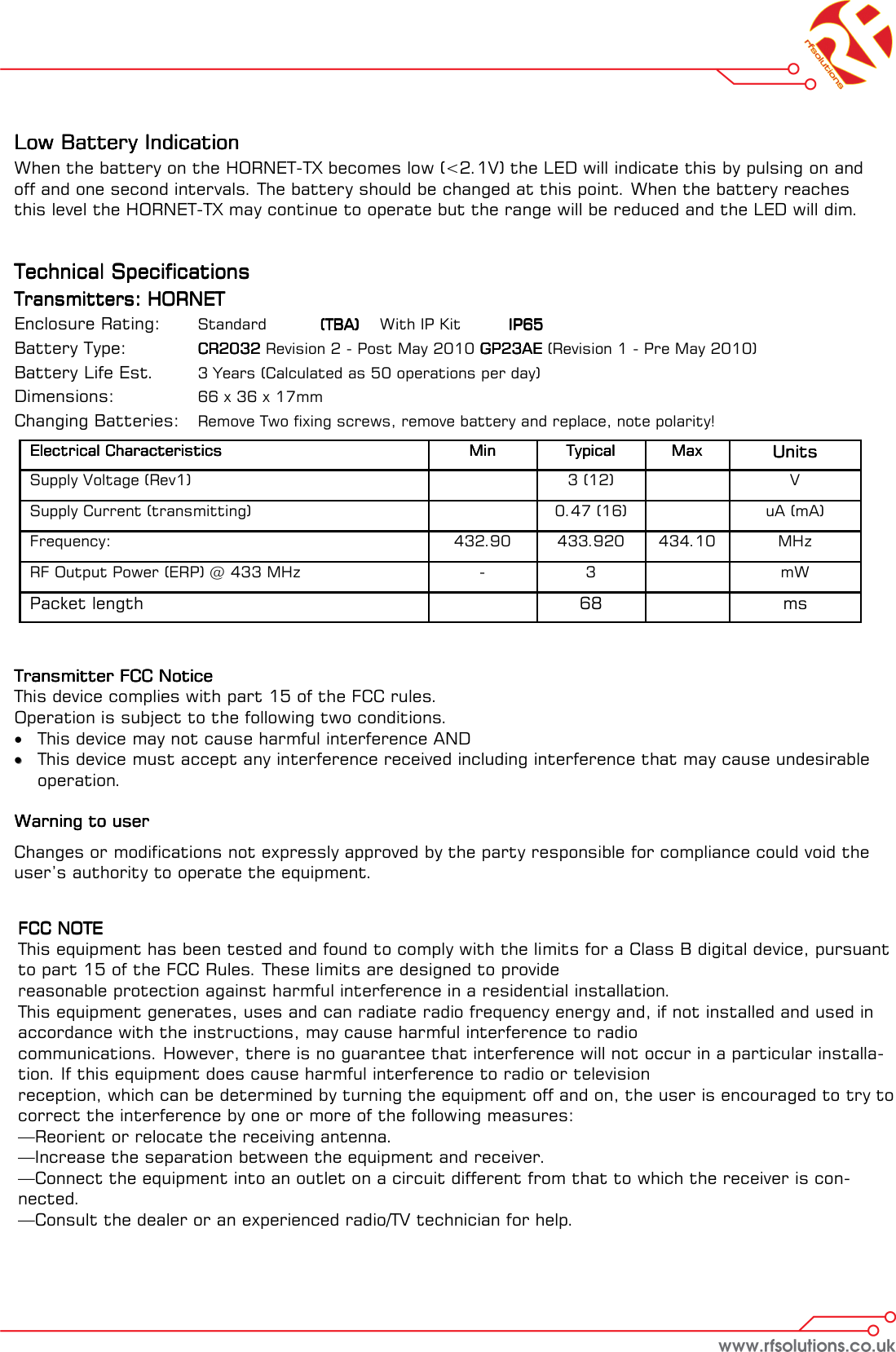
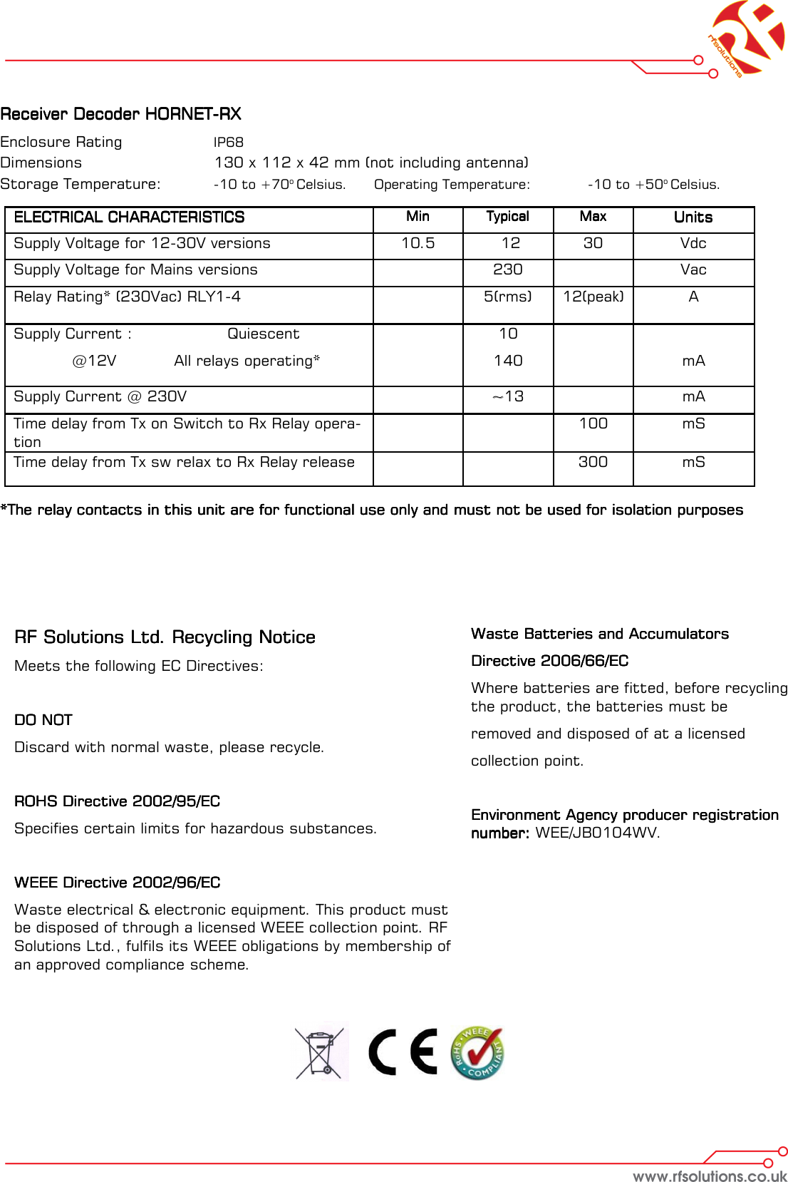
RF Solutions HORNET-TX Transmitter keyfob for Hornet systems User Manual DS HORNET 10 pub

RF Solutions Ltd. Transmitter keyfob for Hornet systems DS HORNET 10 pub

DS-HORNET-10

HORNET Remote Control SystemsHORNET Remote Control SystemsHORNET Remote Control SystemsHORNET Remote Control Systems    DS HORNET-10      DescriptionDescriptionDescriptionDescription    Supplied complete ready to go the HORNET is a rugged IP68 weatherproof remote control system. Built in mounting points and easy wiring using High Quality screw  Terminals. With a range of up to100m the HORNET is ideal for a wide variety of switching appli-cations. Additional transmitters may be added using the ‘learn’ process, any button on the transmitter can be used to control one or many outputs of the receiver.   •  Up to 100metres Range •  1 – 3 Button versions •  12-30Vdc 0r 230Vac versions  •  Reliable FM Technology •  Up to four 1000W Relay switches •  Waterproof Receiver (IP68)  •  Momentary or Latching Relays •  Any Switch Map to Any Relay Output •  General Purpose Remote General Purpose Remote General Purpose Remote General Purpose Remote SwitchingSwitchingSwitchingSwitching    •  Electric GatesElectric GatesElectric GatesElectric Gates    •  Roller Shutter DoorsRoller Shutter DoorsRoller Shutter DoorsRoller Shutter Doors    •  Garden LightingGarden LightingGarden LightingGarden Lighting
    HORNETHORNETHORNETHORNET----S1 / HORNETS1 / HORNETS1 / HORNETS1 / HORNET----S2 / HORNETS2 / HORNETS2 / HORNETS2 / HORNET----S3 (12S3 (12S3 (12S3 (12----32Vdc Receivers)32Vdc Receivers)32Vdc Receivers)32Vdc Receivers)    The HORNET system provides up to 4 isolated switches each capable of switching up to 6A @230V  1.    Open the enclosure by removing the two fixing screws from the base of the   enclosure and remove the antenna, the board should then slide out. 2.  Wire the power as shown on Fig 1.1 3.  Wire your chosen switch as required 4.  Once the receiver is set-up; transmitter button 1 will switch relay 1 (button   two to relay two and so on). Each button press will change the state of the   relay (i.e. one press for on, one press for off).
Advanced OperationAdvanced OperationAdvanced OperationAdvanced Operation        To pair a new transmitter switch follow this procedureTo pair a new transmitter switch follow this procedureTo pair a new transmitter switch follow this procedureTo pair a new transmitter switch follow this procedure    Any transmitter button can be configured to operate any of the receiver relays. Pair any Transmitter switch with a receiver relay by following this procedure: 1.  Select the receiver output relay to learn to: 2.  Briefly press the receiver Pairing switch (S2) once 3.  The Learn LED will flash once to indicate relay 1 is selected 4.  After the LED stops flashing, press the Learn switch again to select the next        relay channel 5.  Repeat step 4 until the required relay is selected. 6.  Press the button on the transmitter you want to learn to the relay. 7.  The Learn LED will flash to indicate Pairing is complete.       Pairing a Transmitter to a ReceiverPairing a Transmitter to a ReceiverPairing a Transmitter to a ReceiverPairing a Transmitter to a Receiver    The only limitation is that each receiver has a maximum memory for up to 40 pairings, these can be from the same or any number of transmitters.   Erasing Receivers Memory Erasing Receivers Memory Erasing Receivers Memory Erasing Receivers Memory     1.  Press and hold the receiver Learn Switch for approx 10 seconds.  2.  When the Learn LED turns ON all memory is erased NOTE:NOTE:NOTE:NOTE: You cannot erase individual Tx encoders      Configuring Relays Configuring Relays Configuring Relays Configuring Relays  The jumper links set the outputs to be Momentary (operates as long as transmitter is operated)  or Latching (Relay changes state each time transmitter is pressed). The jumper links are made / removed by the small link ‘cap’ placed over the pin header.           See Fig 1.1 for location of jumper pins. Link PositionsLink PositionsLink PositionsLink Positions   RelaysRelaysRelaysRelays  LK1LK1LK1LK1   LK2LK2LK2LK2   RLY 1RLY 1RLY 1RLY 1   RLY 2RLY 2RLY 2RLY 2   RLY 3RLY 3RLY 3RLY 3   RLY 4RLY 4RLY 4RLY 4  Closed   Closed   Mom   Mom   Mom   Mom  Closed   Open   Mom   Mom   Latch   Latch  Open   Closed   Mom   Latch   Latch   Latch  Open   Open   Latch   Latch   Latch   Latch
    HORNETHORNETHORNETHORNET----S1M / HORNET S2M  (230Vac Powered Receivers)S1M / HORNET S2M  (230Vac Powered Receivers)S1M / HORNET S2M  (230Vac Powered Receivers)S1M / HORNET S2M  (230Vac Powered Receivers)    The HORNET system provides up to 4 isolated switches each capable of switching up to 6A @230V  1.    Open the enclosure by removing the two fixing screws from the base of the            enclosure and the antenna, the board should then slide out. 2.  Wire the power as shown on Fig 1.2 3.  Wire your chosen switch as required 4.    Once the receiver is set-up transmitter button 1 will switch relay 1 (button two    relay two and so on). Each button will change the state of the relay (i.e. one   press for on, one press for off).
Advanced OperationAdvanced OperationAdvanced OperationAdvanced Operation        Please Note:Please Note:Please Note:Please Note:    During Learn and Erase the relays operate at high speed. They should be isolated from sensi-tive equipment during this process.     To Pair additional Transmitter buttons to receiver Relay #1To Pair additional Transmitter buttons to receiver Relay #1To Pair additional Transmitter buttons to receiver Relay #1To Pair additional Transmitter buttons to receiver Relay #1    1.  Apply power the receiver and wait 10secs for the unit to enter ‘normal operation’ mode. 2.  Switch the receiver unit OFF and then ON again in ~1sec intervals FOURFOURFOURFOUR times finally leaving the unit powered. 3.  The receiver emits a continuous ‘Click’ to confirm it is now in ‘learn’ Mode 4.  Press the chosen transmitter button.  5.  The receiver will acknowledge by sounding the a single ’buzz’  6.  Learn Process complete.   To Pair additional Transmitter buttons to receiver Relay #2To Pair additional Transmitter buttons to receiver Relay #2To Pair additional Transmitter buttons to receiver Relay #2To Pair additional Transmitter buttons to receiver Relay #2    1.  Apply power the receiver and wait 10secs for the unit to enter ‘normal operation’ mode. 2.  Switch the receiver unit OFF and then ON again in ~1sec intervals SIXSIXSIXSIX times finally leaving the unit powered. 3.  The receiver emits a continuous ‘Click’ to confirm it is now in ‘learn’ Mode 4.  Press the chosen transmitter button.  5.  The receiver will acknowledge by sounding the two  ’buzzes’  6.  Learn Process complete.   Erasing Receivers Memory Erasing Receivers Memory Erasing Receivers Memory Erasing Receivers Memory     1.  Power the receiver unit up and wait 10 seconds for the unit to enter ‘normal operation’ mode. 2.  Switch the unit off and then on again at ~1 second intervals TENTENTENTEN times, leaving the unit powered. 3.  The receiver confirms Erase cycle complete by giving three short ‘Buzzes’ 4.  The unit has now erased all encoder data.  NOTE:NOTE:NOTE:NOTE: You cannot erase individual Tx encoders   Configuring Receiver RelaysConfiguring Receiver RelaysConfiguring Receiver RelaysConfiguring Receiver Relays    The jumper links set the outputs to be Momentary (operates as long as transmitter is operated)  or Latching (Relay changes state each time transmitter is pressed). The jumper links are made/removed by the small link ‘cap’ placed over the pin header.  Link1 controls relay Output #1 Link2 controls relay Output #2  Link FITTED =  LATCHING Link OPEN =   MOMENTARY  Image shows, RLY2  Momentary, RLY1 Latched.
System Part Numbers System Part Numbers System Part Numbers System Part Numbers                         Operating from 12     Operating from 12     Operating from 12     Operating from 12----30Vdc30Vdc30Vdc30Vdc         Systems Operating at 230VacSystems Operating at 230VacSystems Operating at 230VacSystems Operating at 230Vac            **Range stated is optimum, direct line of sight. In worst conditions this can be reduced by over 50% Part NumberPart NumberPart NumberPart Number     DescriptionDescriptionDescriptionDescription  HORNET-TX1   Transmitter 1 switch  HORNET-TX2   Transmitter 2 switch  HORNET-TX3   Transmitter 3 switch  HORNET -TX-IPKIT   ’O’ Ring, Seals Transmitter to IP65  Additional TransmittersAdditional TransmittersAdditional TransmittersAdditional Transmitters    Part NumberPart NumberPart NumberPart Number     DescriptionDescriptionDescriptionDescription  FrequencyFrequencyFrequencyFrequency    (MHz)(MHz)(MHz)(MHz)  Range**Range**Range**Range**  (Metres)(Metres)(Metres)(Metres)  HORNET-S1    System 1 channel   433.92   100  HORNET-S2    System 2 channel   433.92   100  HORNET-S3   System 3 channel   433.92   100  Part NumberPart NumberPart NumberPart Number     DescriptionDescriptionDescriptionDescription  FrequencyFrequencyFrequencyFrequency    (MHz)(MHz)(MHz)(MHz)  Range**Range**Range**Range**  (Metres)(Metres)(Metres)(Metres)  HORNET-S1M    System 1 channel   433.92   100  HORNET-S2M    System 2 channel   433.92   100  Bespoke VersionsBespoke VersionsBespoke VersionsBespoke Versions    Custom versions available with your own logo and or protocol. Please contact Sales for further info.
Low Battery IndicationLow Battery IndicationLow Battery IndicationLow Battery Indication    When the battery on the HORNET-TX becomes low (<2.1V) the LED will indicate this by pulsing on and off and one second intervals. The battery should be changed at this point. When the battery reaches this level the HORNET-TX may continue to operate but the range will be reduced and the LED will dim.      Technical SpecificationsTechnical SpecificationsTechnical SpecificationsTechnical Specifications    Transmitters: HORNETTransmitters: HORNETTransmitters: HORNETTransmitters: HORNET    Enclosure Rating:  Standard  (TBA)    (TBA)    (TBA)    (TBA)    With IP Kit   IP65 IP65 IP65 IP65     Battery Type:    CR2032CR2032CR2032CR2032 Revision 2 - Post May 2010 GP23AE GP23AE GP23AE GP23AE (Revision 1 - Pre May 2010)  Battery Life Est.  3 Years (Calculated as 50 operations per day) Dimensions:    66 x 36 x 17mm  Changing Batteries:   Remove Two fixing screws, remove battery and replace, note polarity!           Transmitter FCC NoticeTransmitter FCC NoticeTransmitter FCC NoticeTransmitter FCC Notice    This device complies with part 15 of the FCC rules. Operation is subject to the following two conditions. •  This device may not cause harmful interference AND ••  This device must accept any interference received including interference that may cause undesirable operation.    Warning to userWarning to userWarning to userWarning to user    Changes or modifications not expressly approved by the party responsible for compliance could void the user’s authority to operate the equipment.  Electrical CharacteristicsElectrical CharacteristicsElectrical CharacteristicsElectrical Characteristics  MinMinMinMin  TypicalTypicalTypicalTypical  MaxMaxMaxMax  UnitsUnitsUnitsUnits  Supply Voltage (Rev1)     3 (12)    V  Supply Current (transmitting)     0.47 (16)     uA (mA)  Frequency:    432.90  433.920  434.10  MHz  RF Output Power (ERP) @ 433 MHz  -  3    mW  Packet length     68    ms FCC NOTEFCC NOTEFCC NOTEFCC NOTE    This equipment has been tested and found to comply with the limits for a Class B digital device, pursuant to part 15 of the FCC Rules. These limits are designed to provide  reasonable protection against harmful interference in a residential installation.  This equipment generates, uses and can radiate radio frequency energy and, if not installed and used in accordance with the instructions, may cause harmful interference to radio  communications. However, there is no guarantee that interference will not occur in a particular installa-tion. If this equipment does cause harmful interference to radio or television  reception, which can be determined by turning the equipment off and on, the user is encouraged to try to correct the interference by one or more of the following measures:  —Reorient or relocate the receiving antenna.  —Increase the separation between the equipment and receiver.  —Connect the equipment into an outlet on a circuit different from that to which the receiver is con-nected.  —Consult the dealer or an experienced radio/TV technician for help.
Receiver Decoder HORNETReceiver Decoder HORNETReceiver Decoder HORNETReceiver Decoder HORNET----RXRXRXRX    Enclosure Rating    IP68   Dimensions      130 x 112 x 42 mm (not including antenna) Storage Temperature:   -10 to +70o Celsius.  Operating Temperature:   -10 to +50o Celsius.   *The relay contacts in this unit are for functional use only and must not be used for isolation purposes*The relay contacts in this unit are for functional use only and must not be used for isolation purposes*The relay contacts in this unit are for functional use only and must not be used for isolation purposes*The relay contacts in this unit are for functional use only and must not be used for isolation purposes ELECTRICAL CHARACTERISTICSELECTRICAL CHARACTERISTICSELECTRICAL CHARACTERISTICSELECTRICAL CHARACTERISTICS  MinMinMinMin  TypicalTypicalTypicalTypical  MaxMaxMaxMax  UnitsUnitsUnitsUnits  Supply Voltage for 12-30V versions   10.5    12   30   Vdc  Supply Voltage for Mains versions    230    Vac Supply Current :    Quiescent   @12V   All relays operating*      10  140         mA  Time delay from Tx on Switch to Rx Relay opera-tion          100   mS  Time delay from Tx sw relax to Rx Relay release           300   mS  Relay Rating* (230Vac) RLY1-4       5(rms)   12(peak)   A  Supply Current @ 230V    ~~13     mA RF Solutions Ltd. Recycling NoticeRF Solutions Ltd. Recycling NoticeRF Solutions Ltd. Recycling NoticeRF Solutions Ltd. Recycling Notice    Meets the following EC Directives:  DO NOTDO NOTDO NOTDO NOT    Discard with normal waste, please recycle.  ROHS Directive 2002/95/ECROHS Directive 2002/95/ECROHS Directive 2002/95/ECROHS Directive 2002/95/EC    Specifies certain limits for hazardous substances.  WEEE Directive 2002/96/ECWEEE Directive 2002/96/ECWEEE Directive 2002/96/ECWEEE Directive 2002/96/EC    Waste electrical & electronic equipment. This product must be disposed of through a licensed WEEE collection point. RF Solutions Ltd., fulfils its WEEE obligations by membership of an approved compliance scheme.     Waste Batteries and Accumulators Waste Batteries and Accumulators Waste Batteries and Accumulators Waste Batteries and Accumulators     Directive 2006/66/ECDirective 2006/66/ECDirective 2006/66/ECDirective 2006/66/EC    Where batteries are fitted, before recycling the product, the batteries must be  removed and disposed of at a licensed  collection point.  Environment Agency producer registration Environment Agency producer registration Environment Agency producer registration Environment Agency producer registration number: number: number: number: WEE/JB0104WV.
Installation diagram Installation diagram Installation diagram Installation diagram                                                                                                                                                       NOT TO SCALENOT TO SCALENOT TO SCALENOT TO SCALE        DisclaimerDisclaimerDisclaimerDisclaimer    Whilst the information in this document is believed to be correct at the time of issue, R.F.Solutions Ltd does not accept any liability whatsoever for its accuracy, adequacy or completeness. No express or implied warranty or representation is given relating to the information contained in this document. R.F.Solutions Ltd reserves the right to make changes and improvements to the product(s) described herein without notice.  Buyers and other users should determine for themselves the suitability of any such information or products for their own particular requirements or specifica-tion(s).  R.F.Solutions Ltd shall not be liable for any loss or damage caused as a result of user’s own determination of how to deploy or use R.F.Solutions Ltd’s products.  Use of R.F.Solutions Ltd products or components in life support and/or safety applications is not authorised except with express written approval. No licences are created, implicitly or otherwise, under any of R.F.Solutions Ltd’s intellectual property rights. Liabil-ity for loss or damage resulting or caused by reliance on the information contained herein or from the use of the product (including liability resulting from negligence or where R.F.Solutions Ltd was aware of the possibility of such loss or damage arising) is excluded. This will not operate to limit or restrict R.F.Solutions Ltd’s liability for death or personal injury resulting from its negligence.

Navigation menu