R F Technologies 30011534001 User Manual Hardware Overview
RF Technologies Inc Hardware Overview
UserManual.wiki
>
R F Technologies
>
30011534001 User Manual
>
Hardware Overview
Contents
1.
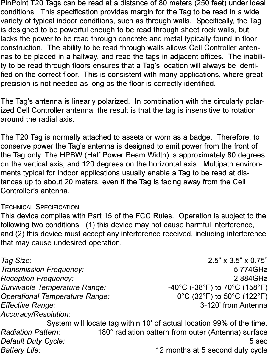
Hardware Overview
2.
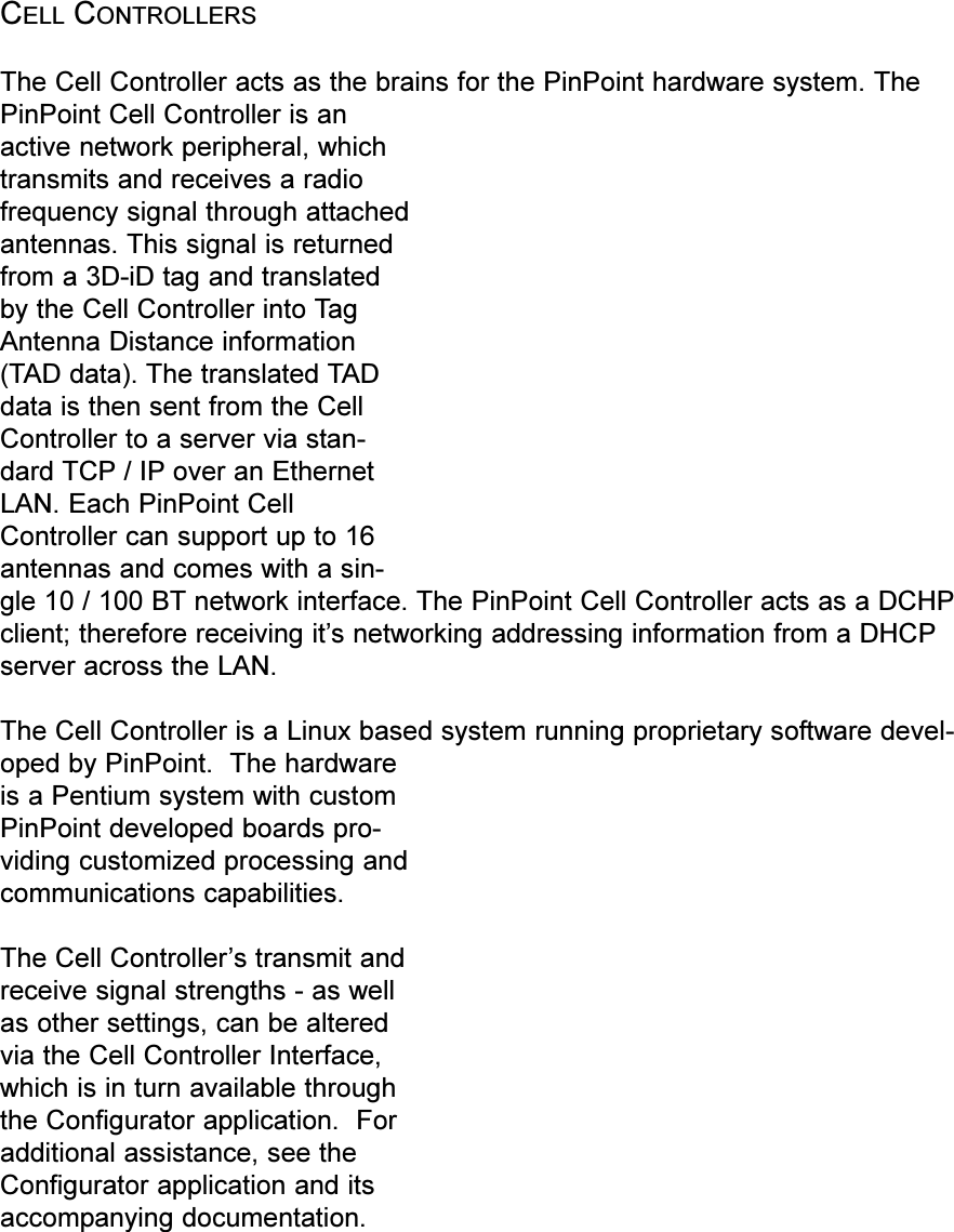
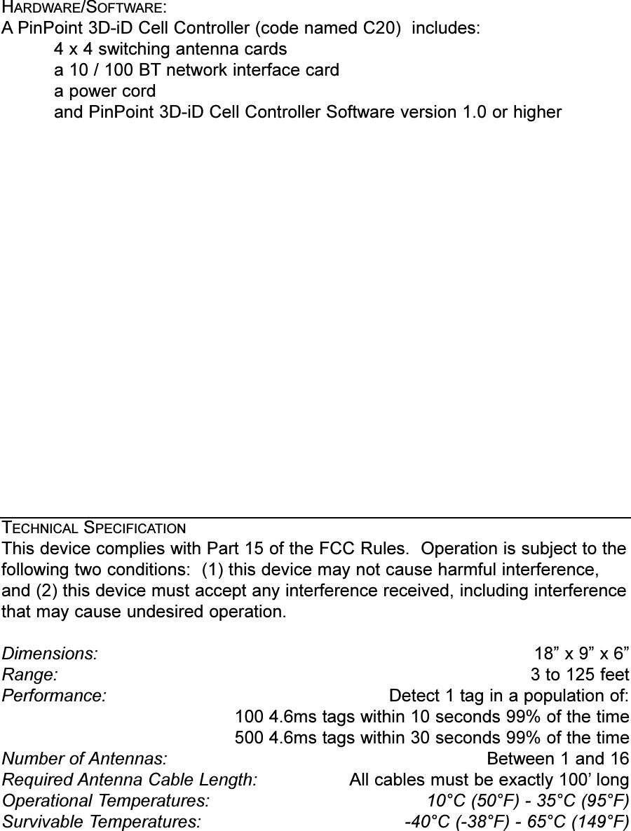
Cell Controller Manual
3.
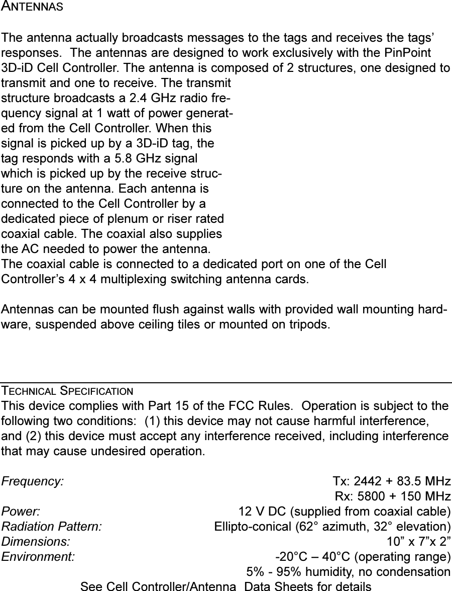
Antenna Manual
Hardware Overview
Navigation menu
Upload a User Manual
Namespaces
Wiki Guide
HTML
PDF
Info
Views
User Manual
Discussion / Help
Navigation