RF Technology 50A 25 - 50 MHz Base Station Transceiver User Manual Receiver operations manual
RF Technology Pty Ltd 25 - 50 MHz Base Station Transceiver Receiver operations manual
Contents
- 1. Receiver operations manual
- 2. Power amplifier operations manual
- 3. Exciter operations manual
Receiver operations manual
Eclipse Series
RF Technology
rfinfo@rftechnology.com.au
November, 2001
R50 Receiver
Operation and Maintenance Manual
This manual is produced by RF Technology Pty Ltd
10/8 Leighton Place, Hornsby NSW 2077 Australia
Copyright © 2001 RF Technology

Page 2 RF Technology R50
CONTENTS CONTENTS
Contents
1 Operating Instructions 1
1.1 Front Panel Controls 4
1.1.1 MON. Volume 4
1.1.2 MON. SQ 4
1.1.3 N. SQ 4
1.1.4 C. SQ 5
1.1.5 LINE 5
1.2 Front Panel Indicators 5
1.2.1 PER LED 5
1.2.2 SQ LED 6
1.2.3 ALARM LED 6
2 Receiver Options 6
2.1 Serial I/O Parameters 6
2.2 Receiver Low Battery Level 7
2.3 Audio High Pass (Notch) Filter 7
2.4 Audio Response 7
2.5 LOOP VOLTS Select 7
2.6 COS Polarity Select 7
2.7 COS Source/Sink Select 7
2.8 Channel Selectable Parameters 7
3 Receiver I/O Connections 8
3.1 25 Pin Connector 8
3.2 9 Pin Front Panel Connector 9
4 Channel Programming and Option Settings 9
4.1 Setting Options 9
4.2 Setting Channel Parameters 10
5 Circuit Description
5.1 R50 Master Schematic (Sheet 1) 11
5.2 Microprocessor (Sheet 2) 12
5.3 RF Section (Sheet 3) 14
5.4 Receiver Section (Sheet 4) 15
5.5 Voltage Controlled Oscillator (Sheet 5) 16
5.6 Audio Processing Section (Sheet 6) 16
5.7 Power Generation Section (Sheet 7) 17
6 Field Alignment (Calibration) Procedure 18
6.1 Standard Test Equipment 18
6.2 Invoking the Calibration Procedure 18
6.3 The "Miscellaneous" Calibration Procedure 19
6.4 The "Line" Calibration Procedure 20
6.5 The "Reference" Calibration Procedure 20
7 Specifications 21
7.1 Overall Description 21
7.1.1 Channel Capacity 21

RF Technology R50 Page 3
CONTENTS CONTENTS
7.1.2 CTCSS 21
7.1.3 Channel Programming 21
7.1.4 Channel Selection 21
7.1.5 Microprocessor 22
7.2 Physical Configuration 22
7.3 Front Panel Controls, Indicators and Test Points 22
7.3.1 Controls 22
7.3.2 Indicators 22
7.3.3 Test Points 22
7.4 Electrical Specifications 23
7.4.1 Power Requirements 23
7.4.2 Frequency Range and Channel Spacing 23
7.4.3 Frequency Synthesizer Step Size 23
7.4.4 Frequency Stability 23
7.4.5 Number of Channels 23
7.4.6 RF Input Impedance 23
7.4.7 IF Frequencies 23
7.4.8 Sensitivity 24
7.4.9 Selectivity 24
7.4.10 Spurious and Image Rejection 24
7.4.11 Intermodulation 24
7.4.12 Modulation Acceptance BW 24
7.4.13 Noise Squelch 24
7.4.14 Carrier Level Squelch 24
7.4.15 Receiver Frequency Spread 24
7.4.16 Receiver Conductive Spurious 25
7.4.17 Audio Frequency Response 25
7.4.18 Audio Output Level 25
7.4.19 Audio Distortion 25
7.4.20 Channel Select Input / Output 25
7.4.21 Carrier Operated Switch Output 26
7.4.22 Current Source/Sink, Collector Voltage 26
7.4.23 CTCSS 26
7.4.24 External Squelch Input 26
7.5 Connectors 26
7.5.1 Antenna Connector 26
7.5.2 Power and I/O Connector 26
7.5.3 Test Connector 27
Appendix A EIA CTCSS Tone Frequencies 28
Appendix C Parts List 29
Appendix C Engineering Diagrams
C.1 Block Diagram
C.2 Circuit Diagrams
C.3 Component Overlay Diagrams

Page 4 RF Technology R50
1 OPERATING INSTRUCTIONS
1 Operating Instructions
1.1 Front Panel Controls
1.1.1 MON. Volume
The Mon. Volume control is used to adjust the volume of the internal loudspeaker and
any external speaker connected to the test socket. It does not effect the level of the 600
Ohm line or direct audio output.
1.1.2 MON.SQ
The MON. SQ. switch allows the normal squelch functions controlling the monitor
output to be disabled. When the switch is in the MON. SQ. position the audio at the
monitor speaker is controlled by the noise detector. The CTCSS, carrier and external
squelch functions are disabled. This can be useful when you are trying to trace the
source of on channel interference or when setting the noise squelch threshold. The
audio from the 600 Ohm line and direct outputs is not effected by the switch position.
1.1.3 N.SQ
The N.SQ trimpot is used to set the noise squelch sensitivity. Use the following
procedure to set the noise squelch to maximum sensitivity.
(a) Set the toggle switch to the MON.SQ. position and set the MON VOLUME control
to 9 o'clock.
(b) Turn the N.SQ. adjustment counter clockwise until the squelch opens and noise is
heard from the speaker. Adjust the VOLUME to a comfortable listening level.
WARNING
Changes or modifications not expressly approved by
RF Technology could void your authority to operate
this equipment. Specifications may vary from those
given in this document in accordance with
requirements of local authorities. RF Technology
equipment is subject to continual improvement and
RF Technology reserves the right to change
performance and specification without further notice.

RF Technology R50 Page 5
1 OPERATING INSTRUCTIONS 1.1.4 C. SQ
(c) In the absence of any on channel signal, Turn the N.SQ. screw clockwise until the
until the noise in the speaker is muted. Then turn the screw two additional turns in the
clockwise direction.
1.1.4 C.SQ
The C.SQ trimpot is used to set the carrier squelch sensitivity. Carrier squelch is useful
at higher signal levels than noise squelch and can be used from 1 - 200 uV input.
It is provided mainly for use in fixed link applications where a high minimum signal to
noise ratio is required or where very fast squelch operation is required for data
transmission. The carrier squelch will open and close in less than 2 mSec.
In most base station applications carrier squelch is disabled by turning the adjustment
counter clockwise until the screw clicks.
The carrier squelch may be set to a predetermined level with the TecHelp software or
by using the following procedure:
(a) First turn the adjustment fully counter-clockwise. Then set the noise squelch as
above.
(b) Connect a source of an on channel signal with the desired threshold level to the
receiver's RF input.
(c) Turn the screw clockwise until the SQ LED goes OFF. Then turn the screw back
until the LED just comes ON.
1.1.5 LINE
The LINE trimpot is used to set the line and direct audio output level. It is normally set
to give 0 dBm ( 775 mV ) to line with a standard input signal equal to 60% of
maximum deviation at 1 KHz. The level can be measured between test socket pins 6 &
1 and set as desired.
1.2 Front Panel Indicators
1.2.1 PWR LED
The PWR LED shows that the dc supply is connected to the receiver and that the
microprocessor is not being held in a RESET state.
Page 6 RF Technology R50
1.2.2 SQ LED 2 RECEIVER OPTIONS
1.2.2.1 SQ LED
The SQ LED comes on when the audio to the line and direct outputs is un-squelched.
The LED and squelch function are controlled by noise, carrier and tone squelch
circuits.
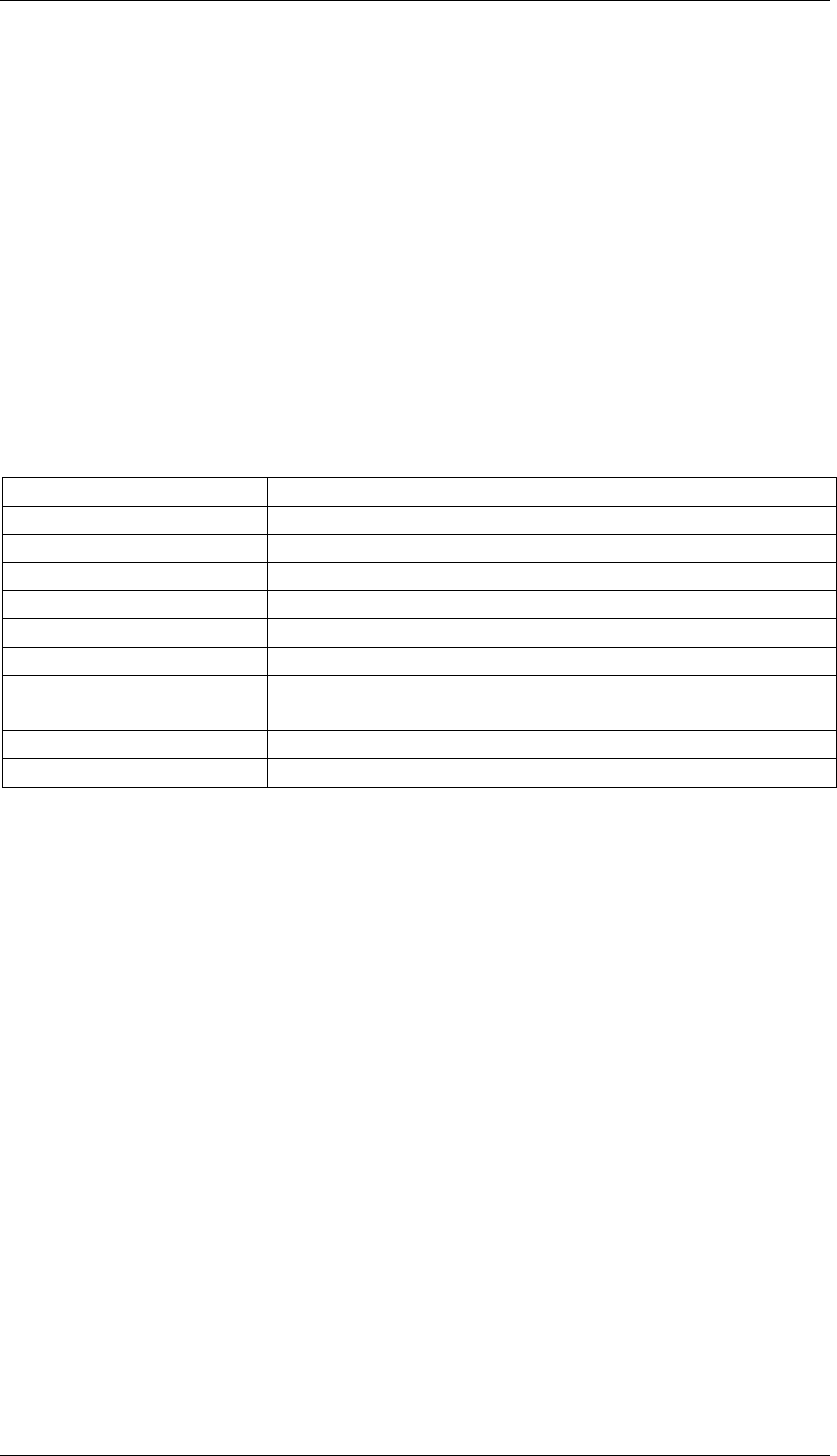
1.2.3 ALARM LED
The ALARM LED can indicate several fault conditions if they are detected by the self
test program. The alarm indicator shows the highest priority fault present. See Table
1.
LED Flash Cadence Fault Condition
9 flashes, pause External PA failure
8 flashes, pause Low dc supply on External PA
7 flashes, pause External PA Over Current Condition
6 flashes, pause External PA Over Temperature
5 flashes, pause Synthesizer unlocked
3 flashes, pause Unable to communicate with External PA
2 flashes, pause The current channel is not programmed or the frequency
is out of range.
1 flash, pause Low dc supply voltage
LED ON continuously Transmitter timed out
Table 1: Interpretations of LED flash cadence
2 Receiver Options
There are many software selectable options. Some options are selected on a per
channel basis, and some are defined globally (i.e. the parameter is fixed irrespective of
which channel is selected). Below is a description of these global parameters
2.1 Serial I/O Parameters
There are two serial ports. There is the main serial port which is brought out to the
front panel connector. This is referred to as PORT0. There is another serial port
which is for factory use only. It is referred to as PORT1.
The baud rate, parity, and whether hardware flow control is enabled can be defined for
PORT0. PORT0 is set by default to 57.6Kbps, with No parity, and No Hardware Flow
Control.

RF Technology R50 Page 7
2 RECEIVER OPTIONS 2.2 Receiver Low Battery Level
2.2 Receiver Low Battery Level
This is factory set to 24.0V, and defines the level of the DC supply that will cause an
Receiver dc supply low alarm.
2.3 Audio High Pass (Notch) Filter
At the audio output ports, the sub tone (CTCSS) can be notched by a high pass filter,
this high pass filter can be software selected as enable or disable (the filter was
bypassed). The default factory setting is audio high pass filter enable.
2.4 Audio Response
The output audio frequency response can be selected as 750uSec. De-emphasis or flat
response, the default factory setting is 750uSec. De-emphasis.
2.5 LOOP Volts Select
The receiver can key up the transmitter with a DC current between Line+ and Line- of
the audio output terminals. If this option is selected enable, it will be active by the
squelch switch, then a 12Vdc supply is applied to the pair through 660 ohms of source
impedance. If this option is disable, the loop is not used. The default factory setting is
LOOP VOLTS enable.
2.6 COS Polarity Select
The COS (Carrier Operated Switch) can be selected as on with Signal or on with no
Signal. The default factory setting is COS on with Signal.
2.7 COS Source/Sink Select
The COS can be used as a DC source or a free switch, if the Source option is selected,
a 12Vdc voltage will be applied between COS+ and COS- terminals when the COS is
off. The default factory setting is COS Source.
2.8 Channel Selectable Parameters
Each channel defines two complete set of parameters. One set of parameters is used
when a transmitter keys up from the PTT-in input, and the other set is used when the
transmitter keys up from the LOOP-in, the PTT switch, or the microphone PTT input.
Each set defines what frequency to use, what CTCSS sub-tone (if any) to use, what

Page 8 RF Technology R50
3.1 25 Pin Connector 3 RECEIVER I/O CONNECTIONS
maximum line deviation to use, what tone deviation to use, what transmit delay (a
delay applied from PTT-in or LOOP-in to transmission), what transmit tail (delay
from PTT-in, or LOOP-in, to transmission being stopped, and No-TONE period (a
period of extra transmission in which No Tone is applied after PTT-in or LOOP-in has
been released.
As well as these parameters, which Line (or Lines) can be selected, and whether the
Lines should have Flat frequency response or have Pre-emphasis applied. Also, it can
Enable or disable the extra 20dB gain pad.
Note that both Line1 and Line 2 can be selected (each with or without pre-emphasis),
and if so, then the two signals will be mixed, and the Line potentiometer will adjust
the level of them both.
3 Receiver I/O Connections
3.1 25 Pin Connector
The female D-shell, 25 pin, connector is the main interface to the transmitter. The pin
connections are described in Table 3.
Function Signal Pins Specification
DC Power +28Vdc(in)
0 Vdc
+5Vdc(out)
+12Vdc(out)
13, 25
1, 14
17
15
+24 to 32 Vdc
Common Voltage
Output for external Logic(100mA)
Output for an external relay(120mA)
Serial
Communications SCLK
MOSI
CH_EN
SPEARE_I/O1
SPARE_SEL
12
6
18
16
5
Serial Clock
Bi-directional Data Pin
Enables Channel Select Shift Register
Spare Input or Output (for future use)
Spare Select (for future use)
600Ω Line
Output
Line+
Line- 8
19 Transformer Isolated Balanced 600Ω
0dBm Output
Carrier Operated
Switch Output COS+
COS- 10
22 Opto Coupled Transistor Switch
Output (10mA)
External Squelch
Input EXT_SQ 11 <1 VDC to Squelch
>2 VDC or pen ckt to un-squelch
External Speaker
Output EXT_SPK 24 AC Coupled External Speaker
Output, 5W @ 4Ω Load
Direct Audio
Output DIR_AUD 21 >10kΩ, AC Coupled Audio Output
2Vp-p @ 3kHz System Deviation
Discriminator
Audio Output DISC_AUD 20 >10kΩ, AC Coupled Un-Squelched
2Vp-p @ 3kHz System Deviation
Sub-Audible
Tone Output SUBTONE 9>10kΩ, AC Coupled Un-Squelched,
2Vp-p @ 3kHz System Deviation
Table 3: Pin connections and explanations for the main 25-pin, D connector

RF Technology R50 Page 9
4 CHANNEL PROGRAMMING AND OPTIONS SELECTIONS
3.2 9 Pin Front Panel Connector
The female D-shell, 9 pin, front panel connector is an RS232 interface for serial
communications to a terminal, a terminal emulator, or to a computer. The pin
connections are described in table 4.
Function Pins Specification Pin name on IBM PC
TXD 2 Transmit Data (Output) RxD
RXD 3 Receive Data (Input) TxD
RTS 8 Request To Send (Output) CTS
CTS 7 Clear To Send (Input) RTS
DTR 6 Data Terminal Ready(Output) DSR
DSR 1 Data Set Ready (Input) DCD
GND 5 GND GND
Table 4: Pin connections for the front panel 9 pin D connector
The pinout for the connector has been chosen so that a straight-through BD9 male to
DB9 female cable can connect the transmitter to any male DB9 serial port on an IBM
PC compatible computer.
Note that for connection to a modem, a cross-over cable will be required.
4 Channel Programming and Option Selections
Channel and tone frequency programming is most easily accomplished with RF
Technology Eclipse50 software. This software can be run on an IBM compatible PC
and can be used to calibrate a T50, R50, and PA50 as well as program channel
information. See the Eclipse 50 users manual for further information.
But the R50 also has its own stand-alone high level interface, which can be accessed
from a VT100 compatible terminal, or terminal emulator (such as HyperTerm which is
available as a standard accessory with Windows).
The pertinent aspects of this High Level Interface are described below.
4.1 Setting Options
Note that any text in italics, represents data output by the R50 firmware, rather than
command line data sent to the R50 firmware.
The R50, after powering up, will issue a command prompt of the form:
R50>
Via a terminal, or a terminal emulator, a user can type various commands in. The basic
command to read parameters is:

Page 10 RF Technology R50
4 CHANNEL PROGRAMMING AND OPTION SELECTIONS
R50> read par parameter_name
Where "parameter_name" is one of the following:
Parameter Name Parameter Function Default Value Parameter Range
LOOP_GEN Generate a LOOP
potential (see 2.5) Off Text: Off or On
PA_LOW_BAT Low Battery Alarm
Level (see 2.4) 20.0 (Volts) Floating Point Number
< 32.0
BAUD_RATE0 Port 0 Baud Rate 57600 (BPS) Decimal number:
300 - 115200
PARITY0 Port 0 Parity None Text: None, Even, or
Odd
FLOW_CONTR
OL Port 0 Flow Control Off (“On” not
yet available) Text: Off
Table 6: Some User Defined Parameters
Note that the parameter names have been shown in upper case, but they can be typed
in upper or lower case.
A parameter can be changed, or added, by typing
R50> set par parameter_name=parameter_value
As for parameter names, the parameter value can be Upper or Lower case if it is a text
value, as against a numeric value.
4.2 Setting Channel Parameters
One can read the data from an existing channel by entering the command:
R50> read chan chan_number
Where chan_number is a number from 0 to 99.
Entering new channel values, or modifying existing ones is possible from the
command line interface, but it is not recommended. It can be done by typing the
following at a command prompt:
R50> set chan chan_number parameter_list
Where chan_number is a number from 0 to 99.
The format of the parameter_list is quite complex. It has 14 fields. Each field can be
separated by a colon(:), comma(,), space, or tab.
For example set chan 0 25.0:35.0,100.0,120.0,0,5,2,0,5,2,10,11,0,3
Field1: Receive Frequency(in MHz). This is 25.0 MHz in the example.

RF Technology R50 Page 11
5 CIRCUIT DESCRIPTION 5.1 R50 Master Schematic (Sheet 1)
Field2: Transmit Frequency(in MHz) if the exciter is keyed up by anything but
PTT-in being asserted. This is 35.0 MHz in the example.
Field3: CTCSS Tone(in Hz) if PTT-in is asserted. This is 100Hz in the example.
Field4: CTCSS Tone(in Hz) if the exciter is keyed up by anything but PTT-in
being asserted. This is 120Hz in the example.
Fields 5,6,7: These define the start-up delay (in hundredths of a second), the transmit
tail (in seconds), and the no tone period (in tenths of a second) if the exciter keys up
from PTT-in being asserted.
Fields 8,9,10: These define the start-up delay (in hundredths of a second), the transmit
tail (in seconds), and the no tone period (in tenths of a second), if the exciter keys up
from anything other than PTT-in being asserted.
Field 11: Selects the line parameter if PTT-in being asserted caused the exciter to key
up. In the example it has disabled the 20dB gain pad, and enabled pre-emphasis on
Line 2 (Line 1 is disabled).
Field 12: Selects the line parameter if anything other than PTT-in being asserted
caused the exciter to key up. In the example it has disabled the 20dB gain pad, and it
would enable pre-emphasis on Line 1 and Line2 (i.e. audio on each input is mixed).
Field 13: Selects the Tone deviation and the Maximum Line deviation if the exciter
keys up from PTT-in being asserted In the example, it has selected the default
maximum line deviation (5kHz), and the default tone deviation of 750Hz. (See Tables
7 and 8)
Field 14: Selects the Tone deviation and the Maximum Line deviation if the exciter
keys up from anything other than PTT-in being asserted In the example, it has
selected a maximum deviation of 2.5kHz, and a maximum tone deviation of 375Hz.
(See Tables 7 and 8)
5 Circuit Description
The following descriptions should be read as an aid to understanding the block and
schematic diagrams given in the appendix of this manual.
There are 7 sheets in the schematic in all.
5.1 R50 Master Schematic (Sheet 1)
Sheet 1, referred to as the "R50 Master Schematic", is a top level sheet, showing four
circuit blocks, and their interconnection with each other, as well as the interconnection
with all connectors and external switches.
P1 is the front panel DB9 RS-232 connector for attachment to a terminal, a terminal
emulator, or to an IBM PC running the Eclipse50 software.

Page 12 RF Technology R50
5.2 Microprocessor (Sheet 2) 5 CIRCUIT DESCRIPTION
P3 represents the rear female DB25 connector.
J1 is the terminal on print circuit board, it is connected to the internal load speaker.
JP2 is for the attachment of an LCD display module. This has been included for later
development.
JP3 is a specialised connector for test and factory configuration use only.
D102, D103, and D104 represent the three front panel LEDs.
5.2 Microprocessor (Sheet 2)
Sheet 2 describes the basic microprocessor circuitry.
The core CPU is the Motorola XC68HC12A0. It is configured in 8 bit data width
mode.
The CPU is clocked by a 14.7456MHz crystal oscillator circuit (top left) comprising
the JFET Q202, and two switching transistors Q203 and Q204.
The CPU contains an 8 channel A/D converter whose inputs are identified as AN0,
AN1, …, AN7.
AN7 is used as LOCK detect inputs from the Locked Loop (PLL) circuits (see 5.6)
AN6 is used to sense the noise squelch level setting.
AN5 is used to sense whether or not the dc supply is within spec or not.
AN4 is used to sense the audio from the discriminator, so the R50 receiver can be used
as a deviation meter.
AN3 and AN1 are inputs from the PLL circuits that sense the bias voltage on the VCO
control varactor for each VCO.
AN2 is used to sense the carrier squelch level setting.
AN0 is used to sense the RF input signal strength which is detected by the IF chip.
FRDY is an output from the flash. It goes low when the Flash starts to write a byte of
data, or erase a block, or erase the whole chip, and it returns to its default high state
when the action requested has completed.
FPSW1, FPSW2 and FPSW3 are three pins that have been reserved for future use as
switch inputs.
LOOP/VOLTS_SEL is a CPU output that when high applies 12V of dc feed to the
audio output.

RF Technology R50 Page 13
5 CIRCUIT DESCRIPTION 5.2 Microprocessor (Sheet 2)
LINE_LEVEL_U/D and LINE_LEVEL_INC are CPU outputs which are reserved for
controlling a digital potentiometer in future.
COS_VOLTS_ON/OFF is a CPU output that when high applies 12VDC feed to COS+
terminal, so that the COS can be selected as +12VDC source or a free switch.
COS_POLARITY is CPU output that when low turns Opto-coupled transistor switch
U601on. It is controlled by the noise squelch detect, carrier squelch, or external
squelch signal
SQ is a CPU output that when low turns 600W line and direct audio path on. It is
controlled by the noise squelch detect, carrier squelch, or external squelch signal
N_BLK_EN is a CPU output that when low turns noise blanker option off.
CTCSS_SEL is a serial bus select pin. It is used to select the FX805 chip(U500),
which is used to decode CTCSS tones. (see 5.5)
PLL_SEL is a serial bus select pin. It is used to select the PLL chip in the PLL circuit
(U302). (See 5.6)
RCV_ADSEL is a serial bus select pin. It selects the quad Digital to Analogue
converter (DAC) that sets the levels for the 12MHz reference oscillator bias voltage,
21.855MHz oscillator bias voltage, noise squelch comparator bias voltage and the
LCD bias circuit. (see 5.4)
CH_EN is a serial bus select. It is brought out to the rear panel and is used to interface
to the channel encoder on the rear daughter-board. (See 5.1)
FLAT and DE_EMPHA are outputs logically inverted each other, when FLAT pin
low, the audio output is flat response, when DE_EMPHA pin low, audio is 750uSec
de-emphasized.
F0_PLL is the F0 outputs of the PLL chip divided by 100. They should be 312.5Hz
square waves, except for brief periods when frequencies are being changed. (See 5.6)
MON_SW is used to sense front panel MON.SQ switch.
LCD_DB7 is an input used to sense if the LCD display module is busy processing the
last command sent to it.
ECLK is a pin that at start-up only, should have the CPU system clock of 7.3728MHz
on it.
SQ_LED, ALARM_LED, are CPU outputs that drive (when low) the SQ LED, and
the ALARM LED on.
T/R_RELAY_H is a spare pin which is not used in R50 receiver.
SCLK, and MOSI are used as the core of a serial bus. SCLK is a clock pin, and MOSI
is a bi-directional data pin.

Page 14 RF Technology R50
5.3 RF Section (Sheet 3) 5 CIRCUIT DESCRIPTION
DBGTX_TTL, DBGRX_TTL are RS232 transmit and receive (TTL) data pins which
are connected to the debug port after conversion to/from RS232 compatible voltage
levels by U202 and U201.
TXD_TTL, RXD_TTL, RTS_TTL, CTS_TTL, DTR_TTL, DSR_TTL, are RS232
data pins which are connected to the main front panel serial port after conversion
to/from RS232 compatible voltage levels by U202 and U201.
N_DET is used to sense the noise squelch output of the receiver section. (see
SUBTONE_IRQ is used to sense the subtone decoded comes from the FX805 (U500).
INT is the CPU interrupt input pin which is used to detect the external squelch signal.
BKGD is a bi-directional I/O pin used to communicate with the core of the CPU. It is
connected to the debug port and is utilised by specialised hardware to control the CPU
externally, even without any firmware being present in the Flash.
The RESET pin is both a low active input and a low active output to the CPU. If
generated externally to the CPU, it forces the CPU into reset, and if the CPU executes
a RESET instruction this pin will be driven low by the CPU.
Whenever there is insufficient volts (< 4.65V) on pin 2 of the MC33064D (U203), it
will keep its RES output low. After the voltage has met the right level it will assert its
output low for another 200 milliseconds. Thus the CPU will be held in reset until
VCC is at the correct level. Thus the PWR_OK LED will only light when VCC is
within specification, and RESET has been released.
S200 is a momentary push-button switch that, when pressed, will cause the CPU to be
reset.
MON_SQ is a CPU output to set the monitor speaker on or off
LCD_RS, LCD_R/W, and LCD_E are reserved for interfacing to an LCD display
module. Note that this feature has not been implemented.
U205 is used to select whether the Flash or RAM is to be read or written.
U207 is a single supply, 5V, TSOP40 Flash chip of size 8, 16, or 32 Megabits, and is
used to store the firmware.
U208 is a 1, or 4, Megabit Static RAM in an SOP-32 package, and is used for both
code and data. The code in the RAM is copied from the Flash, at start-up.
5.3 RF Section (Sheet 3)
Sheet 3 is a schematic of RF section, which itself refers to two other subsheets.
U301 is a quad Digital to Analogue converter (DAC), OUTA (pin2) is used to adjust
the 3rd local oscillator frequency. OUTB (pin1) is used to adjust frequency of the
12MHz reference. OUTC(pin16) is used to set the noise squelch comparator offset

RF Technology R50 Page 15
5 CIRCUIT DESCRIPTION 5.4 Receiver Section (Sheet 4)
voltage. OUTD (pin15) is used to set the LCD bias voltage, this feature is not used in
this version. Communication between U301 and MicroController U204 is via the
serial bus.
U302 is a dual channels PLL chip, X301 is the reference for both PLL channels, PLL
channel 1 is for the 1st VCO, channel 2 is for the 2nd VCO. C315, C317, C327,
R316 and R317 are components of loop filter for the 1st VCO, C316, C328, C329,
R330 and R331 are for loop filter of the 2nd VCO. U303A, U303D are buffers that
send the bias voltage of two VCOs to MicroController U204.
U304A, U304B convert the F0LD of the PLL chip to a square wave by a division of
100, and send the signal to MicroController U204.
5.4 Receiver Section (Sheet 4)
RF input signal (25MHz-50MHz) is filtered by a high pass filter (C401, C402, C403,
C407, C415, C416, C417, C419, C420 and L401, L404, L405, L406) and a low pass
filter (C404, C405, C406, C421, C422 and L402, L403, L407, L408). Q401 is the
front-end amplifier, capacitors and coils between Q401 and C440 provide additional
filtering for RF signal amplified by Q401. MX401 is a double balanced mixer which
converts the RF signal to the 1st IF, the frequency of the 1st IF is at least three times
higher than the highest RF frequency to obtain a good image and spurious rejection. In
R50 receiver, the 1st IF frequency is 246MHz.
Q402 is used to amplify the 1st IF signal, FIL401 is a SAW filter which provides an
excellent spurious rejection for the 1st IF. The filtered IF signal is then fed to a double
balanced mixer MX402, the output of MX402 (the 2nd IF) is amplified by Q403, the
2nd IF frequency is selected at 21.4MHz to avoid the interference from in band RF
signal.
Q404 is a gate of the noise blanker, the gate is controlled by the impulse noise
detector.
FIL404 and FIL405 are two 21.5MHz crystal filters which can be equivalent as a four
pole crystal filter, the filer provides minimum 40dB attenuation at adjacent channel
frequency. C448, C477, L423 and components between FIL405 and U401 are
matching network for the filter.
U401 is IF receiver IC which includes mixer, oscillator, amplifiers and discriminator.
The frequency of oscillator is 21.855MHz, it can be tuned by the 3rd_LO_ADJ
voltage.
The product of mixer is 455KHz, build in amplifiers of U401, FIL402 and FIL403
provide sufficient gain and adjacent channel rejection for 455KHz IF signal to be
discriminated.
Pin9 of U401 is recovered audio output, C411, C412, C413 and R441, R444 and
U402A are working as a high pass filter to eliminate the audio frequency, U402B
amplifies the FM noise signal, D403 and C438 convert the noise level to a DC voltage.
U402C works as a comparator, the offset voltage can be set by the OUTC of U301.

Page 16 RF Technology R50
5.5 Voltage Controlled Oscillator (Sheet 5) 5 CIRCUIT DESCRIPTION
Pin8 of U401 is the other recovered audio output which can be muted by pin5,
discriminated audio signal is amplified by U605A to a sufficient level for line level
detector, then fed into Audio Section (Sheet 6).
Pin7 of U401 is the Radio Signal Strength Indicator (RSSI) output, U402D is a buffer
for send RSSI voltage to MicroController.
Q405 and Q406 are amplifiers for impulse noise signal, the impulse noise is then
detected by D401 and U403, C489, R450 and U404 form a 2uSec noise blanking pulse
when the impulse noise is detected. Q408 converts the CMOS level to a required
switch level to control the noise blanker gate Q404.
U303B and Q407 work as gain control circuit to reduce the Intermodulation which is
produced from impulse noise amplifiers.
5.5 Voltage Controlled Oscillator (Sheet 5)
There are two similar VCO circuits in this sheet, the difference between these two
VCO is component values, so only one VCO circuit is illustrated in this section.
Q501, C532, C533, C534 and L501 are working as a Colpitts oscillator, the frequency
of the oscillator is decided by the tuning voltage of a varactor D501 which comes from
the loop filter of the 1st PLL. Q503 is used to reduce the noise on power supply. D503,
R517 and C519 are working as AGC circuit to improve output of the VCO signal.
MMIC amplifier MA501 provides about 20dB gain for the VCO signal and feeds it to
the PLL chip. MA502 and MA503 provide about 30dB gain of the VCO signal to
drive the double balanced mixer MX401, Q506 and those components of which value
with "*" are not used in this version, they will be used in case of higher drive power
which is required by some high LO level mixer.
5.6 Audio Processing Section (Sheet 6)
U605B, R642, R643, R644, C626, C627 and C628 are working as a 3KHz low pass
filter, in addition, the discriminated audio signal level from U605A is attenuated by
the low pass filter to fit the dynamic range limitation of CTCSS chip U602.
U602 is a CTCSS tone encoder and decoder. The integrated circuit is also capable of
generating and receiving DCS signals, but at this stage this has not been implemented.
The CPU accesses U602 via the serial bus using MOSI, SCLK, and the low active
Select signal CTCSS_SEL.
4MHz crystal X401 is used as the reference of the CTCSS decoding. The build-in high
pass filter of the audio path (Pin 10 to Pin 11) can eliminate the subtone, this filter can
be bypassed by the MicroController. The subtone output from Pin17 is amplified by
U605C, through C604 connected to the DB25 terminal on rear panel.

RF Technology R50 Page 17
5 CIRCUIT DESCRIPTION 5.7 Power Generator Section (Sheet 7)
U609B, U607A and U607B are working as a flat/de-emphasis response switch, it can
be selected by control signal FLAT and DE_EMPHA from the MicroController U204.
U607D and U607C is the squelch switch for line output and speaker.
U609C is the amplifies for 600W line output, U609D is the amplifier for direct audio
output, the output level of 600W line an direct audio are adjustable via VR601 on the
front panel.
U604 is the power amplifier for internal and external speaker, the power level can be
adjusted by VR602 on the front panel.
Depending on the squelch, RL602 will apply a 12VDC to the 600W line output when
loop function is selected. If the loop function is not used, RL602 always stay in the
position of which C619 is bypassed. The position of RL602 is controlled by the signal
LOOP/VOLTS_SEL from the MicroController U204.
Opto-coupled transistor Switch U601 provides a COS (Carrier Operated Switch)
output which is controlled by COS_POLARITY signal from the MicroController. The
output COS+ and COS- can be used as +12V DC source or a free switch depending on
the status of the relay RL601, RL601 is controlled by COS_VOLTS_ON/OFF signal
from the MicroController U204.
Discriminated audio level is detected by D604 and C623, signal LINE_LEVEL is
connected to the analog-digital converter input pin of the MicroController for
calibration purpose.
5.7 Power Generation Section (Sheet 7)
There are three switch-mode dc-dc converters in the board. These use monolithic
converters based on the National LM2595. Two of the converters are 12V converters
and one is a 5V converter.
The power in to the whole exciter is the voltage rail 28V.
U907 converts this down to 12V.
U908 is set up as an inverter, and uses the 12V rail to create -12V.
U909 converts the +12V rail to +5V for all the digital circuitry.
The +12V rail is used to power the two on-board relays, as well as up to one extra off-
board relay. It is also dropped, via a linear regulator (U910) to produce the +10V rail,
which in turn is dropped by another linear regulator U911 to produce +5Q.
Similarly U913 and U914 are linear regulators that produce -10V and -5V from the -
12V output of U908.
+2.5Vand -2.5V are not used in the R50 receiver, the reason of being showed on the
schematic diagram is to keep same design of the T50 power generation section.

Page 18 RF Technology R50
6 FIELD ALIGNMENT (CALIBRATION) PROCEDURE
D911 is a 4.096V (3%) reference diode. Its output is buffered by U906 which then
produces a reference voltage rail Vref, which is used by the CPU's A/D converter, and
the DACs.
6 Field Alignment (Calibration) Procedure
6.1 Standard Test Equipment
Some, or all of the following equipment will be required:
Power supply set to 28Vdc, with current >1A.
RF Signal Generator
50 Ohm Output impedance
Frequency range 25-50MHz
FM modulation at 1KHz
3KHz peak deviation for 25KHz or 20KHz channel spacing
Frequency Counter
The accuracy should be at least 0.5ppm, preferably 0.1ppm
True RMS AC voltmeter, and a DC voltmeter.
6.2 Invoking the Calibration Procedure
The R50 has in-built firmware to perform calibration. This firmware requests the user
for information as to meter readings, and/or to attach or adjust the AF signal generator.
The firmware based calibration program can be accessed from a terminal, a terminal
emulator, or the Eclipse50 terminal emulator.
As for Section 4.1, the firmware, after power up, issues the following prompt:
R50>
Via a terminal, or a terminal emulator, a user can type various commands in. The basic
command to start the calibration procedure is:
R50> cal calibration_type
Where "calibration_type" is one of:
(a) misc: Miscellaneous parameters are defined and calibrated
(b) line: Line1, Line2, Dir Aud (Tone), and microphone inputs are tested and
calibrated.
(c) ref: The reference oscillators are adjusted and calibrated
(d) all : (which does all the above)

RF Technology R50 Page 19
6 FIELD ALIGNMENT (CALIBRATION) PROCEDURE
6.3 The "Miscellaneous" Calibration Procedure
R50> cal misc
This procedure should not normally be invoked as part of any field maintenance.
The program will print out the Model Name and Serial Number of the exciter. If these
parameters haven't already been defined (e.g. at an initial calibration, at the factory,
the service personnel will be prompted to enter these values).
Then it will ask the operator to enter the value of Vref (as measured at TP913, see
5.7).
Measure the voltage, at TP913 (Vref)
and type it on the command line...
Unless the reference diode D911 has been replaced, this should not be done. The user
should simply hit the Enter key to bypass this operation. If, though, D911 has been
replaced for some reason, then, the lid of the unit should be removed, and the voltage
measured. TP913 can be found just above JP12 (near the centre of the exciter).
Then the receiver low battery alarm level will be asked for. If the current value is
acceptable, the User need only hit the Enter key on the keyboard. If another value is
preferred, then that value can be typed in.
For example:
The Exciter's Low Battery Alarm is 24V
If this is correct enter <RET>,
else enter the new value: 26
In this example, the low Battery Alarm level is changed to 26V.
Then the user will be prompted for serial port baud rates, parities etc. Please leave
these parameters unchanged unless you are familiar with how to change such
parameters on your PC. The Eclipse50 software will expect 57600 BPS, and No
Parity, and No Flow Control. Note well, that if you do change any of these, the
change will not take effect until you power down the receiver and then power it up
again. (As an alternative to power cycling the receiver, and if the cover is off the
receiver, you may simply press switch momentary push-button S200 (see 5.2).
Then the following questions are:
Is Flat frequency response on by default (Y/N)?
Is COS purely a sink of current (Y/N)?
Is COS Asserted when the Squelch is closed (Y/N)?
Is COS UnAsserted when the Squelch is open (Y/N)?
Is LOOP Asserted when the Squelch is closed (Y/N)?
Is LOOP UnAsserted when the Squelch is open (Y/N)?
Always hit "Enter key" unless the value other than default is required, note use the "Y"
key if default value need to be changed.

Page 20 RF Technology R50
6 FIELD ALIGNMENT (CALIBRATION) PROCEDURE
6.4 Line Calibration Procedure
R50> cal line
This procedure is used for calibrating the RF RSSI level reading, FM modulation
(deviation) reading. Also this procedure is used to set the 600 Ohm audio line output
level, Noise squelch level and Carrier squelch level. Simply follow the instruction of
the software as bellow:
Attach an RF signal generator to the input.
Set the RF output to 37.5MHz,
and an input level of -110dBm
with a 1kHz tone and 3kHz deviation.
Adjust the Volume Pot until the DIR AUD output
is 388mV.(eqvt to 0dBm into 600 ohms)
Enter <RET> when done.
Set the RF signal generator's output to -60dBm
Enter <RET> when done.
rssi_scale is 0.417dBm/dac step, and rssi offset is -137.500dBm) --- for example
Adjust the Modulation to only 1KHz max deviation
Enter <RET> when done.
deviation_scale is 1.000dBm/dac step, and
deviation offset is .000dBm --- for example
Adjust the Carrier Squelch to the desired level
Enter <RET> when set.
-99.5 --- for example
Enter the Fast Noise Threshold(in dBm):
Enter the Carrier Alarm Threshold(in dBm):
Set the RF generator output to the desired level ( < -105dBm ),
and adjust the N.SQ adjustment counter clockwise
until the squelch opens, thence turn it clockwise
until the noise is muted.
Enter <RET> when done
6.5 The "Reference" Calibration Procedure
R50> cal ref
To compensate for crystal ageing and other parameters that drift, the following
procedure should be performed approximately once per year.
Open the cover of the receiver, find out the test point TP209 on receiver PCB, using a
frequency counter to measure the frequency and follow the instruction as bellow:

RF Technology R50 Page 21
7 SPECIFICATIONS 7.1 Overall Description
Measure the ECLK frequency, accurate to 0.5Hz
and enter the result(in MHz, eg 7.3727965)
Measure the E clock frequency again, and enter yes(y/Y)
if less than 1Hz from prev. freq, or re-enter the frequency
Connect an RF generator to the input
and with output freq of 37.5MHz and output level of -100dBm
Enter <RET> when done.
7 SPECIFICATIONS
7.1 Overall Description
The receiver is a frequency synthesized, narrow band, HF, FM unit which can be used
in conjunction with transmitter and power supply modules as a base station or as a
stand alone receiver. All necessary control and 600 ohm line interface circuitry is
included.
7.1.1 Channel Capacity
Although most applications are single channel, it can be programmed for up to 100
channels, numbered 0--99. This is to provide the capability of programming all
channels into all of the transmitters used at a given site.
7.1.2 CTCSS
Full EIA subtone Capability is built into the modules. The CTCSS tone can be
programmed for each channel. This means that each channel number can represent a
unique RF and tone frequency combination.
7.1.3 Channel Programming
The channel information is stored in non-volatile memory and can be programmed via
the front panel connector using a PC, and/or RF Technology software.
7.1.4 Channel Selection
Channel selection is by eight channel select lines connected to the rear panel that
mounts on the rear DB25 female connector.
A BCD active high code applied to the lines selects the required channel. This can be
supplied by pre-wiring the rack connector so that each rack position is dedicated to a
fixed channel. Alternatively, thumb-wheel switch panels are available.

Page 22 RF Technology R50
7.1.5 Microprocessor 7 SPECIFICATIONS
7.1.5 Microprocessor
A microprocessor is used to control the synthesizer, tone squelch, calibration, fault
monitoring and reporting, RSSI reading, deviation measuring, option setting and
facilitate channel frequency programming.
7.2 Physical Configuration
The receiver is designed to fit in a 19 inch rack mounted sub-frame. The installed
height is 4 RU (178 mm) and the depth is 350 mm. The receiver is 63.5 mm or two
Eclipse modules wide.
7.3 Front Panel Controls, Indicators, and Test Points
7.3.1 Controls
Mute Defeat Switch - Toggle (Overrides CTCSS and carrier squelch at the monitor
output)
Monitor Speaker volume - Knob
Line output Level - screw driver adjust multi-turn pot
Noise Squelch setting - screw driver adjust multi-turn pot
Carrier Squelch Setting- screw driver adjust multi-turn pot
7.3.2 Indicators
Power ON - Green LED
Squelch Open - Yellow LED
Fault Indicator - Flashing Red LED
7.3.3 Test Points
There are no front panel test points. All important test points are monitored by the
firmware.

RF Technology R50 Page 23
7 SPECIFICATIONS 7.4.1 Power Requirements
7.4 Electrical Specifications
7.4.1 Power Requirements
Operating Voltage - 16 to 32 Vdc
Current Drain - 0.5A Maximum
Polarity - Negative Ground
7.4.2 Frequency Range and Channel Spacing
The R50, as a single model, covers the full band, currently the R50 receiver works in
20KHz and 25KHz channel spacing. It can also work in as low as 6.25KHz channel
spacing if the narrow band-width IF filter is used.
7.4.3 Frequency Synthesizer Step Size
The specified frequency can be any multiple of 1250Hz.
7.4.4 Frequency Stability
±5 PPM over 0 to +60 C, standard for 25KHz and 20KHz channel spacing
7.4.5 Number of Channels
100, numbered 00 - 99
7.4.6 RF Input Impedance
50W
7.4.7 IF Frequencies
1st IF frequency 246MHz
2nd IF frequency 21.4MHZ
3rd IF frequency 455KHz

Page 24 RF Technology R50
7.4.8 Sensitivity 7 SPECIFICATIONS
7.4.8 Sensitivity
-119 dBm for 12dB SINAD
-116 dBm for 20dB Quieting
7.4.9 Selectivity
80dB per RS204C
7.4.10 Spurious and Image Rejection
90dB
7.4.11 Intermodulation
80dB
7.4.12 Modulation Acceptance BW
7.5KHz
7.4.13 Noise Squelch
(a) Adjustment rang 6-26dB SINAD
(b) Attack time 20mSec. Above 20dB Quieting
(c) Release Time 150mSec. At 20dB Quieting decreasing to 20mSec. Above
2uV preset threshold
(d) Hysteresis Equal to approximately 2dB noise quieting
7.4.14 Carrier Level Squelch
Carrier level squelch can be used when it is necessary to set the opening point above
26 dB SINAD as may be required in link applications. The minimum adjustment range
is 0.5 to 200 uV.
7.4.15 Receiver Frequency Spread
Less than 1dB change in sensitivity over the band

RF Technology R50 Page 25
7 SPECIFICATIONS 7.4.16 Receiver Conducted Spurious Emission
7.4.16 Receiver Conducted Spurious Emission
Less than -67dBm from 1 to 3000MHz
7.4.17 Audio Frequency Response
(a) 600 Ohm Line and Direct Output
+1/-3 dB 300 - 3000 Hz relative to either a flat response or 750 uSec. de-emphasis
(b) Sub-Audio Output
+1/-3dB 67 - 250 Hz
7.4.18 Audio Output Level
(a) 600 Ohm Line
Adjustable -10 to +10 dBm
(b) Monitor Loudspeaker
5 Watts with external speaker, 0.3 Watt with internal speaker
(c) Discriminator and Sub-Audio
Nominally equal to 1 volt peak at rated system deviation
7.4.19 Audio Distortion
With 750 uSec. De-Emphasis
Less than 3% at 1 KHz and 60% of rated system deviation
With Flat Response
Less than 10% at 1 KHz and 60% of rated system deviation
7.4.20 Channel Select Input/Output
Coding
8 lines BCD coded 00-99
Logic Input Levels
0 = < 0.4 Volts
1 = > 3.5 Volts
Internal 100K pull down resistors selects Ch. 00 when all inputs are O/C.

Page 26 RF Technology R50
7.4.21 Carrier Operated Switch Output 7 SPECIFICATIONS
7.4.21 Carrier Operated Switch Output
Floating Opto-Coupler Output
The carrier operated switch output is via an Opto-coupler. Collector and emitter
connections are available to allow connection for source or sink.
The Opto-coupler can be linked inside the receiver to be on when a carrier is detected
or to be on in the absence of carrier.
Connection to Remote Switch via 600 Ohm Line
Internal connections are provided by a relay so that 12VDC can be connected to the
600 Ohm line for use over a single pair.
7.4.22 Current Source/Sink, Collector Voltage
Ic = 10 mA Maximum
Vc = 30 Volts Max
7.4.23 CTCSS
The CTCSS decoding is provided by a U602. This provides programmable decoding
of all 38 EIA and 12 other common tones. See Appendix C for tone squelch
frequencies.
7.4.24 External Squelch Input
An external input is provided to squelch or mute the receiver audio output. This may
be used in conjunction with an external decoder or to mute the receiver during
transmissions.
The External Squelch Input can be connected to the T/R Relay pin on Eclipse
transmitters mute the receiver during transmission.
7.5 Connectors
7.5.1 Antenna Connector
Type N Female Mounted on the module rear panel
7.5.2 Power & I/O Connector
25 pin "D" Male Mounted on the rear panel

RF Technology R50 Page 27
7 SPECIFICATIONS 7.5.3 Test Connector
7.5.3 Test Connector
9 pin "D" Female mounted on the front panel
Page 28 RF Technology R50
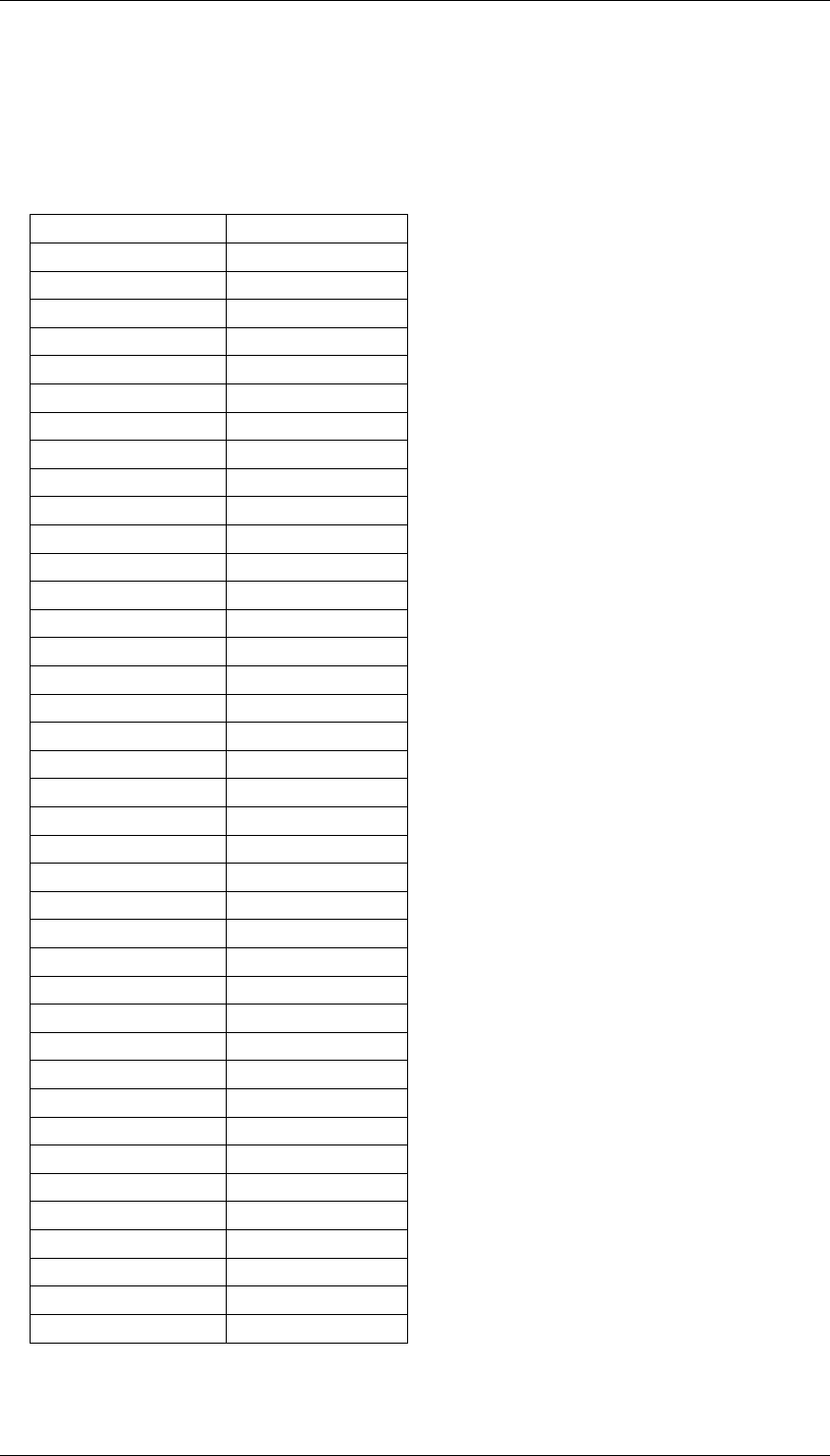
APPENDIX A
APPENDIX A
EIA CTCSS TONE FREQUENCIES
Frequency EIA Number
No Tone
67.0 A1
69.4
71.9 B1
74.4 C1
77.0 A2
79.7 C2
82.5 B2
85.4 C3
88.5 A3
91.5 C4
94.8 B3
100.0 A4
103.5 B4
107.2 A5
110.9 B5
114.8 A6
118.8 B6
123.0 A7
127.3 B7
131.8 A8
136.5 B8
141.3 A9
146.2 B9
151.4 A10
156.7 B10
162.2 A11
167.9 B11
173.8 A12
179.9 B12
186.2 A13
192.8 B13
203.5 A14
210.7 B14
218.1 A15
225.7 B15
233.6 A16
241.8 B16
250.3 A17

R50 PARTS LIST
RF Technology R50 Page 29
B R50 Parts List
Main PCB Assembly Parts
Ref. Description Part Number
C101 EMI Filter ARRY 100PF SMD 34/NFA3/1100
C102 EMI Filter ARRY 100PF SMD 34/NFA3/1100
C103 EMI Filter ARRY 100PF SMD 34/NFA3/1100
C201 Capacitor 100N+80/-20% Y5V 25V 0603 46/63Y1/100N
C202 Capacitor 100N+80/-20% Y5V 25V 0603 46/63Y1/100N
C203 Capacitor 100N+80/-20% Y5V 25V 0603 46/63Y1/100N
C204 Capacitor 100N+80/-20% Y5V 25V 0603 46/63Y1/100N
C205 Capacitor 100N+80/-20% Y5V 25V 0603 46/63Y1/100N
C206 Capacitor 100N+80/-20% Y5V 25V 0603 46/63Y1/100N
C207 Capacitor 100N+80/-20% Y5V 25V 0603 46/63Y1/100N
C208 Capacitor 100N+80/-20% Y5V 25V 0603 46/63Y1/100N
C209 Capacitor 10N+/-10% X7R 50V 0603 46/63X1/010N
C210 Capacitor 100N+80/-20% Y5V 25V 0603 46/63Y1/100N
C211 Capacitor 100N+80/-20% Y5V 25V 0603 46/63Y1/100N
C212 Capacitor 100N+80/-20% Y5V 25V 0603 46/63Y1/100N
C214 Capacitor 100N+80/-20% Y5V 25V 0603 46/63Y1/100N
C215 Capacitor 100N+80/-20% Y5V 25V 0603 46/63Y1/100N
C216 Capacitor 100N+80/-20% Y5V 25V 0603 46/63Y1/100N
C217 Capacitor 100N+80/-20% Y5V 25V 0603 46/63Y1/100N
C219 Capacitor Electrolytic 10U 16V 6032 42/3300/010U
C220 Capacitor 100N+80/-20% Y5V 25V 0603 46/63Y1/100N
C221 Capacitor 100N+80/-20% Y5V 25V 0603 46/63Y1/100N
C222 Capacitor 100N+80/-20% Y5V 25V 0603 46/63Y1/100N
C224 Capacitor 100N+80/-20% Y5V 25V 0603 46/63Y1/100N
C225 Capacitor 100N+80/-20% Y5V 25V 0603 46/63Y1/100N
C226 Capacitor 100N+80/-20% Y5V 25V 0603 46/63Y1/100N
C301 Capacitor 100N+80/-20% Y5V 25V 0603 46/63Y1/100N
C302 Capacitor 100N+80/-20% Y5V 25V 0603 46/63Y1/100N
C303 Capacitor 100N+80/-20% Y5V 25V 0603 46/63Y1/100N
C304 Capacitor 100N+80/-20% Y5V 25V 0603 46/63Y1/100N
C305 Capacitor 100N+80/-20% Y5V 25V 0603 46/63Y1/100N
C306 Capacitor 100N+80/-20% Y5V 25V 0603 46/63Y1/100N
C307 Capacitor 100N+80/-20% Y5V 25V 0603 46/63Y1/100N
C308 Capacitor 100N+80/-20% Y5V 25V 0603 46/63Y1/100N
C309 Capacitor 100N+80/-20% Y5V 25V 0603 46/63Y1/100N
C310 Capacitor 100N+80/-20% Y5V 25V 0603 46/63Y1/100N
C311 Capacitor Electrolytic 10U 16V 6032 42/3300/010U
C312 Capacitor Electrolytic 10U 16V 6032 42/3300/010U
C313 Capacitor Electrolytic 10U 16V 6032 42/3300/010U
C314 Capacitor 100N+80/-20% Y5V 25V 0603 46/63Y1/100N
C315 Capacitor 10N+/-10% X7R 50V 0603 46/63X1/010N
C316 Capacitor 10N+/-10% X7R 50V 0603 46/63X1/010N
C317 Capacitor 10N+/-5% NPO 50V 1206 46/26N1/010N
C318 Capacitor Electrolytic 10U 16V 6032 42/3300/010U
C319 Capacitor Electrolytic 10U 16V 6032 42/3300/010U

R50 PARTS LIST
Page 30 RF Technology R50
Ref. Description Part Number
C320 Capacitor 100P+/-5% NPO 50V 0603 46/63N1/100P
C321 Capacitor 100P+/-5% NPO 50V 0603 46/63N1/100P
C322 Capacitor 18P+/-5% NPO 50V 0603 46/63N1/018P
C324 Capacitor 33P+/-5% NPO 50V 0603 46/63N1/033P
C327 Capacitor 1U5+/-10% 10V TANT 1206 42/STA1/01U5
C328 Capacitor Electrolytic L ESR 16V 100U 7343 42//STA1/02U2
C329 Capacitor 10N+/-5% NPO 50V 1206 46/26N1/010N
C330 Capacitor 100N+80/-20% Y5V 25V 0603 46/63Y1/100N
C401 Capacitor 120P+/-5% NPO 50V 0603 46/63N1/120P
C402 Capacitor 120P+/-5% NPO 50V 0603 46/63N1/120P
C403 Capacitor 120P+/-5% NPO 50V 0603 46/63N1/120P
C404 Capacitor 120P+/-5% NPO 50V 0603 46/63N1/120P
C405 Capacitor 120P+/-5% NPO 50V 0603 46/63N1/120P
C406 Capacitor 120P+/-5% NPO 50V 0603 46/63N1/120P
C407 Capacitor 1N+/-5% NPO 50V 1206 46/3300/01N0
C408 Capacitor 1N+80/-20% Y5V 25V 0603 46/63X1/001N
C409 Capacitor 1N+80/-20% Y5V 25V 0603 46/63X1/001N
C410 Capacitor 100P+/-5% NPO 50V 0603 46/63N1/100P
C411 Capacitor 330P+/-5% NPO 50V 1206 46/63N1/330P
C412 Capacitor 330P+/-5% NPO 50V 1206 46/63N1/330P
C413 Capacitor 330P+/-5% NPO 50V 1206 46/63N1/330P
C415 Capacitor 100P+/-5% NPO 50V 0603 46/63N1/100P
C416 Capacitor 150P+/-5% NPO 50V 0603 46/63N1/150P
C417 Capacitor 150P+/-5% NPO 50V 0603 46/63N1/150P
C418 Capacitor 120P+/-5% NPO 50V 0603 46/63N1/120P
C419 Capacitor 270P+/-5% NPO 50V 0603 46/63N1/270P
C420 Capacitor 180P+/-5% NPO 50V 0603 46/63N1/180P
C421 Capacitor 68P+/-5% NPO 50V 0603 46/63N1/068P
C422 Capacitor 68P+/-5% NPO 50V 0603 46/63N1/068P
C423 Capacitor 390P +/-5% NPO 50V 0603 46/63N1/390P
C424 Capacitor 100N+80/-20% Y5V 25V 0603 46/63Y1/100N
C425 Capacitor 100N+80/-20% Y5V 25V 0603 46/63Y1/100N
C426 Capacitor 100N+80/-20% Y5V 25V 0603 46/63Y1/100N
C427 Capacitor 100N+80/-20% Y5V 25V 0603 46/63Y1/100N
C428 Capacitor 100N+80/-20% Y5V 25V 0603 46/63Y1/100N
C429 Capacitor 100N+80/-20% Y5V 25V 0603 46/63Y1/100N
C430 Capacitor 100N+80/-20% Y5V 25V 0603 46/63Y1/100N
C431 Capacitor 100N+80/-20% Y5V 25V 0603 46/63Y1/100N
C432 Capacitor 100N+80/-20% Y5V 25V 0603 46/63Y1/100N
C433 Capacitor 100N+80/-20% Y5V 25V 0603 46/63Y1/100N
C434 Capacitor 100N+80/-20% Y5V 25V 0603 46/63Y1/100N
C435 Capacitor 120P+/-5% NPO 50V 0603 46/63N1/120P
C436 Capacitor 100N+80/-20% Y5V 25V 0603 46/63Y1/100N
C437 Capacitor 100N+80/-20% Y5V 25V 0603 46/63Y1/100N
C438 Capacitor 100N+80/-20% Y5V 25V 0603 46/63Y1/100N
C439 Capacitor 10N+/-10% X7R 50V 0603 46/63X1/010N
C440 Capacitor 120P+/-5% NPO 50V 0603 46/63N1/120P
C441 Capacitor 1N+80/-20% Y5V 25V 0603 46/63X1/001N
C442 Capacitor 68P+/-5% NPO 50V 0603 46/63N1/068P
C443 Capacitor 100P+/-5% NPO 50V 0603 46/63N1/100P
C444 Capacitor 120P+/-5% NPO 50V 0603 46/63N1/120P

R50 PARTS LIST
RF Technology R50 Page 31
Ref. Description Part Number
C445 Capacitor 68P+/-5% NPO 50V 0603 46/63N1/068P
C446 Capacitor 120P+/-5% NPO 50V 0603 46/63N1/120P
C447 Capacitor 47P+/-5% NPO 50V 0603 46/63N1/047P
C448 Capacitor 5P6+/-0.25 NPO 50V 0603 46/63N1/05P6
C449 Capacitor 5P6+/-0.25 NPO 50V 0603 46/63N1/05P6
C450 Capacitor 2P7+/-0.25 NPO 50V 0603 46/63N1/02P7
C451 Capacitor 10P+/-5% NPO 50V 0603 46/63N1/010P
C452 Capacitor 100N+80/-20% Y5V 25V 0603 46/63Y1/100N
C453 Capacitor 100N+80/-20% Y5V 25V 0603 46/63Y1/100N
C454 Capacitor 120P+/-5% NPO 50V 0603 46/63N1/120P
C455 Capacitor 120P+/-5% NPO 50V 0603 46/63N1/120P
C456 Capacitor 68P+/-5% NPO 50V 0603 46/63N1/068P
C457 Capacitor 1N+80/-20% Y5V 25V 0603 46/63X1/001N
C458 Capacitor 1N+80/-20% Y5V 25V 0603 46/63X1/001N
C459 Capacitor 10N+/-10% X7R 50V 0603 46/63X1/010N
C460 Capacitor 10N+/-10% X7R 50V 0603 46/63X1/010N
C461 Capacitor 10N+/-10% X7R 50V 0603 46/63X1/010N
C462 Capacitor 1N+80/-20% Y5V 25V 0603 46/63X1/001N
C463 Capacitor 1N+80/-20% Y5V 25V 0603 46/63X1/001N
C464 Capacitor 56P+/-5% NPO 50V 0603 46/63N1/056P
C466 Capacitor 120P+/-5% NPO 50V 0603 46/63N1/120P
C467 Capacitor 5P6+/-0.25 NPO 50V 0603 46/63N1/05P6
C468 Capacitor 33P+/-5% NPO 50V 0603 46/63N1/033P
C469 Capacitor 15P+/-5% NPO 50V 0603 46/63N1/015P
C470 Capacitor 470P+/-10% NPO 50V 0603 46/63N1/470P
C471 Capacitor 4P7+/-0.25 NPO 50V 0603 46/63N1/04P7
C473 Capacitor 2P7+/-0.25 NPO 50V 0603 46/63N1/02P7
C474 Capacitor 56P+/-5% NPO 50V 0603 46/63N1/056P
C475 Capacitor 15P+/-5% NPO 50V 0603 46/63N1/015P
C476 Capacitor 1U+80/-20% Y5V 25V 1206 45/Y5X7/1U16
C477 Capacitor 18P+/-5% NPO 50V 0603 46/63N1/018P
C478 Capacitor 18P+/-5% NPO 50V 0603 46/63N1/018P
C479 Capacitor 22P+/-5% NPO 50V 0603 46/63N1/022P
C480 Capacitor 1N+80/-20% Y5V 25V 0603 46/63X1/001N
C481 Capacitor 1U+80/-20% Y5V 25V 1206 45/Y5X7/1U16
C482 Capacitor 33P+/-5% NPO 50V 0603 46/63N1/033P
C483 Capacitor 10N+/-10% X7R 50V 0603 46/63X1/010N
C484 Capacitor Electrolytic L ESR 16V 33U 6032 41/SELC/033U
C485 Capacitor 1N+80/-20% Y5V 25V 0603 46/63X1/001N
C486 Capacitor 1U+80/-20% Y5V 25V 1206 45/Y5X7/1U16
C487 Capacitor 100N+80/-20% Y5V 25V 0603 46/63Y1/100N
C488 Capacitor 1U+80/-20% Y5V 25V 1206 45/Y5X7/1U16
C489 Capacitor 390P +/-5% NPO 50V 0603 46/63N1/390P
C491 Capacitor 100N+80/-20% Y5V 25V 0603 46/63Y1/100N
C492 Capacitor 100N+80/-20% Y5V 25V 0603 46/63Y1/100N
C493 Capacitor 100N+80/-20% Y5V 25V 0603 46/63Y1/100N
C494 Capacitor 100N+80/-20% Y5V 25V 0603 46/63Y1/100N
C495 Capacitor 100N+80/-20% Y5V 25V 0603 46/63Y1/100N
C496 Capacitor 10P+/-5% NPO 50V 0603 46/63N1/010P
C501 Capacitor 2P2+/-0.25 NPO 50V 0603 46/63N1/02P2
C503 Capacitor Electrolytic 10U 16V 6032 42/3330/010U

R50 PARTS LIST
Page 32 RF Technology R50
Ref. Description Part Number
C504 Capacitor Electrolytic 10U 16V 6032 42/3330/010U
C505 Capacitor Electrolytic 10U 16V 6032 42/3330/010U
C506 Capacitor 1U+80/-20% Y5V 25V 1206 45/Y5X7/1U16
C507 Capacitor Electrolytic 10U 16V 6032 42/3330/010U
C508 Capacitor 100N+80/-20% Y5V 25V 0603 46/63Y1/100N
C509 Capacitor Electrolytic 10U 16V 6032 42/3330/010U
C511 Capacitor 100N+80/-20% Y5V 25V 0603 46/63Y1/100N
C512 Capacitor 100N+80/-20% Y5V 25V 0603 46/63Y1/100N
C513 Capacitor 100N+80/-20% Y5V 25V 0603 46/63Y1/100N
C514 Capacitor 100N+80/-20% Y5V 25V 0603 46/63Y1/100N
C515 Capacitor 100N+80/-20% Y5V 25V 0603 46/63Y1/100N
C516 Capacitor 100N+80/-20% Y5V 25V 0603 46/63Y1/100N
C518 Capacitor 10N+/-10% X7R 50V 0603 46/63X1/010N
C519 Capacitor 1N+80/-20% Y5V 25V 0603 46/63X1/001N
C520 Capacitor 1N+80/-20% Y5V 25V 0603 46/63X1/001N
C521 Capacitor 10N+/-10% X7R 50V 0603 46/63X1/010N
C522 Capacitor 120P+/-5% NPO 50V 0603 46/63N1/120P
C523 Capacitor 120P+/-5% NPO 50V 0603 46/63N1/120P
C524 Capacitor 1N+80/-20% Y5V 25V 0603 46/63X1/001N
C525 Capacitor 10N+/-10% X7R 50V 0603 46/63X1/010N
C526 Capacitor 150P+/-5% NPO 50V 0603 46/63N1/150P
C527 Capacitor 1N+80/-20% Y5V 25V 0603 46/63X1/001N
C528 Capacitor 10N+/-10% X7R 50V 0603 46/63X1/010N
C529 Capacitor 150P+/-5% NPO 50V 0603 46/63N1/150P
C530 Capacitor 22P+/-5% NPO 50V 0603 46/63N1/022P
C531 Capacitor 22P+/-5% NPO 50V 0603 46/63N1/022P
C532 Capacitor 10P+/-5% NPO 50V 0603 46/63N1/010P
C533 Capacitor 4P7+/-0.25 NPO 50V 0603 46/63N1/04P7
C534 Capacitor 10P+/-5% NPO 50V 0603 46/63N1/010P
C535 Capacitor 10P+/-5% NPO 50V 0603 46/63N1/010P
C536 Capacitor 15P+/-5% NPO 50V 0603 46/63N1/015P
C537 Capacitor 15P+/-5% NPO 50V 0603 46/63N1/015P
C538 Capacitor 15P+/-5% NPO 50V 0603 46/63N1/015P
C539 Capacitor 10N+/-10% X7R 50V 0603 46/63X1/010N
C541 Capacitor 10N+/-10% X7R 50V 0603 46/63X1/010N
C542 Capacitor 10N+/-10% X7R 50V 0603 46/63X1/010N
C543 Capacitor 10N+/-10% X7R 50V 0603 46/63X1/010N
C544 Capacitor 10N+/-10% X7R 50V 0603 46/63X1/010N
C545 Capacitor 10N+/-10% X7R 50V 0603 46/63X1/010N
C547 Capacitor 100N+80/-20% Y5V 25V 0603 46/63Y1/100N
C548 Capacitor 120P+/-5% NPO 50V 0603 46/63N1/120P
C549 Capacitor 120P+/-5% NPO 50V 0603 46/63N1/120P
C550 Capacitor 22P+/-5% NPO 50V 0603 46/63N1/022P
C551 Capacitor 120P+/-5% NPO 50V 0603 46/63N1/120P
C552 Capacitor 330P+/-5% NPO 50V 1206 46/63N1/330P
C553 Capacitor 330P+/-5% NPO 50V 1206 46/63N1/330P
C554 Capacitor 120P+/-5% NPO 50V 0603 46/63N1/120P
C555 Capacitor 4P7+/-0.25 NPO 50V 0603 46/63N1/04P7
C556 Capacitor 22P+/-5% NPO 50V 0603 46/63N1/022P
C557 Capacitor 22P+/-5% NPO 50V 0603 46/63N1/022P
C558 Capacitor Electrolytic 10U 16V 6032 42/3330/010U

R50 PARTS LIST
RF Technology R50 Page 33
Ref. Description Part Number
C559 Capacitor Electrolytic 10U 16V 6032 42/3330/010U
C560 Capacitor Electrolytic 10U 16V 6032 42/3330/010U
C561 Capacitor 4P7+/-0.25 NPO 50V 0603 46/63N1/04P7
C563 Capacitor 150P+/-5% NPO 50V 0603 46/63N1/150P
C564 Capacitor 22P+/-5% NPO 50V 0603 46/63N1/022P
C601 Capacitor 1U+80/-20% Y5V 25V 1206 45/Y5X7/1U16
C602 Capacitor 1U+80/-20% Y5V 25V 1206 45/Y5X7/1U16
C604 Capacitor Electrolytic BIPOL 50V 22U+/-20%
RB.2.4 41/BP01/022U
C605 Capacitor 1U+80/-20% Y5V 25V 1206 45/Y5X7/1U16
C606 Capacitor 1U+80/-20% Y5V 25V 1206 45/Y5X7/1U16
C609 Capacitor 1U+80/-20% Y5V 25V 1206 45/Y5X7/1U16
C610 Capacitor 10N+/-5% NPO 50V 1206 46/26N1/010N
C611 Capacitor 100N+80/-20% Y5V 25V 0603 46/63Y1/100N
C612 Capacitor 33P+/-5% NPO 50V 0603 46/63N1/033P
C613 Capacitor 33P+/-5% NPO 50V 0603 46/63N1/033P
C614 Capacitor 1U+80/-20% Y5V 25V 1206 45/Y5X7/1U16
C615 Capacitor 1U+80/-20% Y5V 25V 1206 45/Y5X7/1U16
C616 Capacitor 100N+80/-20% Y5V 25V 0603 46/63Y1/100N
C617 Capacitor 100N+80/-20% Y5V 25V 0603 46/63Y1/100N
C618 Capacitor ELC BIP 50V 22U+/-20% RB.2.4 41/BP01/022U
C619 Capacitor ELC BIP 50V 22U+/-20% RB.2.4 41/BP01/022U
C620 Capacitor 100N+80/-20% Y5V 25V 0603 46/63Y1/100N
C621 Capacitor Electrolytic 10U 16V 6032 42/3330/010U
C622 Capacitor 22N+/-10% X7R 50V 0603 45/X7R1/022N
C623 Capacitor 100N+80/-20% Y5V 25V 0603 46/63Y1/100N
C624 Capacitor Electrolytic 470U 25V RB.2.4 41/2001/470U
C625 Capacitor Electrolytic 470U 25V RB.2.4 41/2001/470U
C626 Capacitor 2N2+/-5% NPO 50V 1812 46/26N1/02N2
C627 Capacitor 10N+/-5% NPO 50V 1206 46/26N1/010N
C628 Capacitor 120P+/-5% NPO 50V 0603 46/63N1/120P
C629 Capacitor 100N+80/-20% Y5V 25V 0603 46/63Y1/100N
C630 Capacitor 22N+/-10% X7R 50V 0603 45/X7R1/022N
C632 Capacitor 100N+80/-20% Y5V 25V 0603 46/63Y1/100N
C633 Capacitor 100N+80/-20% Y5V 25V 0603 46/63Y1/100N
C634 Capacitor 100N+80/-20% Y5V 25V 0603 46/63Y1/100N
C635 Capacitor 100N+80/-20% Y5V 25V 0603 46/63Y1/100N
C636 Capacitor 100N+80/-20% Y5V 25V 0603 46/63Y1/100N
C901 Capacitor Electrolytic L ESR 16V 33U 6032 41/SELC/033U
C902 Capacitor Electrolytic L ESR 470U 35V RB.2/.4 41/200L/470U
C903 Capacitor Electrolytic L ESR 16V 33U 6032 41/SELC/033U
C913 Capacitor Electrolytic 1000U 16V RB.2/.4 41/2001/1000
C915 Capacitor 100N+80/-20% Y5V 25V 0603 46/63Y1/100N
C920 Capacitor 100N+80/-20% Y5V 25V 0603 46/63Y1/100N
C923 Capacitor 100N+80/-20% Y5V 25V 0603 46/63Y1/100N
C924 Capacitor Electrolytic 10U 16V 6032 42/3330/010U
C925 Capacitor Electrolytic 10U 16V 6032 42/3330/010U
C926 Capacitor 100N+80/-20% Y5V 25V 0603 46/63Y1/100N
C927 Capacitor 100N+80/-20% Y5V 25V 0603 46/63Y1/100N
C928 Capacitor Electrolytic 10U 16V 6032 42/3330/010U
C929 Capacitor 100N+80/-20% Y5V 25V 0603 46/63Y1/100N

R50 PARTS LIST
Page 34 RF Technology R50
Ref. Description Part Number
C930 Capacitor Electrolytic 10U 16V 6032 42/3330/010U
C931 Capacitor 100N+80/-20% Y5V 25V 0603 46/63Y1/100N
C933 Capacitor 100N+80/-20% Y5V 25V 0603 46/63Y1/100N
C935 Capacitor Electrolytic L ESR 470U 35V RB.2/.4 41/200L/470U
C936 Capacitor Electrolytic L ESR 16V 33U 6032 41/SELC/033U
C937 Capacitor Electrolytic L ESR 16V 33U 6032 41/SELC/033U
C938 Capacitor Electrolytic L ESR 16V 100U 7343 41/SELD/100U
C939 Capacitor Electrolytic L ESR 6.3V 100U 6032 41/SELC/100U
C940 Capacitor Electrolytic 10U 16V 6032 42/3330/010U
C941 Capacitor Electrolytic 10U 16V 6032 42/3330/010U
C943 Capacitor Electrolytic 10U 16V 6032 42/3330/010U
D102 Diode LED Red RT ANG MTG 21/1010/LEDR
D103 Diode LED Yellow RT ANG MTG 21/1010/LEDY
D104 Diode LED Green RT ANG MTG 21/1010/LEDG
D200 Diode Dual GP BAV99 SOT23 21/3010/AV99
D301 Diode V Capacitor MMBV109 SOT23 21/3060/V109
D401 Diode Schotky BAT17 SOT23 21/3010/0017
D403 Diode Dual GP BAV99 SOT23 21/3010/AV99
D404 Diode Dual GP BAV99 SOT23 21/3010/AV99
D405 Diode Schotky BAT17 SOT23 21/3010/0017
D406 Diode V FilterCapacitor MMBV109 SOT23 21/3060/V109
D407 Diode Zen 5V1 BZX84C5V1 SOT23 21/3040/C5V1
D501 Diode VCapacitor MMBV105G SOT23 21/3060/105G
D502 Diode VCapacitor MMBV109 SOT23 21/3060/V109
D503 Diode Schotky BAT17 SOT23 21/3010/0017
D504 Diode Schotky BAT17 SOT23 21/3010/0017
D601 Diode GP 50V 1A SMD 24/SMA1/4004
D602 Diode GP 50V 1A SMD 24/SMA1/4004
D603 Diode Dual GP BAV99 SOT23 21/3010/AV99
D604 Diode Dual GP BAV99 SOT23 21/3010/AV99
D605 Diode Dual GP BAV99 SOT23 21/3010/AV99
D906 Diode Schotky 40V 1A SMD 24/BRM1/40T3
D907 Diode Schotky 40V 1A SMD 24/BRM1/40T3
D908 Diode Schotky 40V 1A SMD 24/BRM1/40T3
D909 Diode Schotky 40V 1A SMD 24/BRM1/40T3
D910 Diode GP 50V 1A SMD 24/SMA1/4004
D911 Diode Zen 4.096V +/-3% SOT-23 29/VREF/0001
Filter401 SAW Filter 246MHz+/-130KHz SMD 33/SAWF/0001
Filter402 Ceramic Filter 455K SMD 34/2000/CFUC
Filter403 Ceramic Filter 455K SMD 34/2000/CFUC
Filter404 Crystal Filter 2 Pole 21.4MHZ HC45U 33/2000/214W
Filter405 Crystal Filter 2 Pole 21.4MHZ HC45U 33/2000/214W
JP2 Connector 14PIN 35/2501/0014
JP3 Connector 2X5PIN 35/7026/0010
L100 Ferrite Bead 2A 1206 37/P034/0001
L101 Ferrite Bead .5A 1206 37/P033/0001
L102 Ferrite Bead .5A 1206 37/P033/0001
L200 Choke 220UH+/-20% 50mA 1812 37/3320/P103
L202 Ferrite Bead .5A 1206 37/P033/0001

R50 PARTS LIST
RF Technology R50 Page 35
Ref. Description Part Number
L203 Ferrite Bead .5A 1206 37/P033/0001
L204 Ferrite Bead .5A 1206 37/P033/0001
L205 Ferrite Bead .5A 1206 37/P033/0001
L301 Ferrite Bead .5A 1206 37/P033/0001
L401 Inductor 246NH+/-5% 37/AC52/246N
L402 Inductor 246NH+/-5% 37/AC52/246N
L403 Inductor 246NH+/-5% 37/AC52/246N
L404 Inductor 422NH+/-5% 37/AC52/422N
L405 Inductor 558NH+/-5% 37/AC52558N
L406 Inductor 380NH+/-5% 37/AC52/380N
L407 Inductor 169NH+/-5% 37/AC52/169N
L408 Inductor 169NH+/-5% 37/AC52/169N
L409 Inductor 680NH+/-10% 1008 37/3320/680N
L410 Inductor 270NH+/-5% 0805 37/8551/270N
L411 Inductor 270NH+/-5% 0805 37/8551/270N
L412 Inductor 220NH+/-5% 0805 37/8551/220N
L413 Inductor 220NH+/-5% 0805 37/8551/220N
L414 Inductor 220NH+/-5% 0805 37/8551/220N
L417 Inductor 100NH+/-5% 0805 37/8551/100N
L419 Inductor 100NH+/-5% 0805 37/8551/100N
L420 Inductor 150NH+/-5% 0805 37/8551/150N
L421 Inductor 680NH+/-10% 1008 37/3320/680N
L422 Inductor 100NH+/-5% 0805 37/8551/100N
L423 Inductor 2U2H+/-5% 1008 37/3320/02U2
L424 Inductor 2U2H+/-5% 1008 37/3320/02U2
L425 Inductor 560NH+/-5% 0805 37/8551/560N
L426 Inductor 3U3H+/-10% 1008 37/3320/03U3
L501 Inductor 18N5H+/-5% 37/AC5118N5
L502 Inductor 3U3H+/-10% 1008 37/3320/03U3
L503 Inductor 3U3H+/-10% 1008 37/3320/03U3
L504 Inductor 220NH+/-5% 0805 37/8551/220N
L505 Inductor 220NH+/-5% 0805 37/8551/220N
L506 Inductor 3U3H+/-10% 1008 37/3320/03U3
L507 Inductor 220NH+/-5% 0805 37/8551/220N
L509 Inductor 220NH+/-5% 0805 37/8551/220N
L510 Inductor 220NH+/-5% 0805 37/8551/220N
L511 Inductor 3U3H+/-10% 1008 37/3320/03U3
L512 Inductor 220NH+/-5% 0805 37/8551/220N
L514 Inductor 27NH+/-5% 0805 37/8551/027N
L515 Inductor 39NH+/-5% 37/AC52/039N
L516 Inductor 33NH+/-5% 0805 37/8551/033N
L901 Choke 33UH+/-20% 200mA SM1812 37/3320/P102
L902 Inductor MSLD 800mA 220U+/-20% SMD 37/MSP1/220U
L903 Inductor MSLD 500mA 68U+/-20% SMD 37/MSP1/068U
L904 Inductor MSLD 1A 100U+/-20% SMD 37/MSP1/100U
L905 Choke 33UH+/-20% 200mA SM1812 37/3320/P102
L906 Ferrite Bead 2A 1206 37/P034/0001
L907 Ferrite Bead 2A 1206 37/P034/0001
L908 Ferrite Bead 2A 1206 37/P034/0001
L909 Ferrite Bead 2A 1206 37/P034/0001
MA501 Amplifier MMIC VAM-6 SOT143 24/3010/VAM6

R50 PARTS LIST
Page 36 RF Technology R50
Ref. Description Part Number
MA502 Amplifier MMIC VAM-6 SOT143 24/3010/VAM6
MA503 Amplifier MMIC VAM-6 SOT143 24/3010/VAM6
MA504 Amplifier MMIC VAM-6 SOT143 24/3010/VAM6
MA505 Amplifier MMIC MWA0211L SOT143 24/3010/211L
MA506 Amplifier MMIC MWA0211L SOT143 24/3010/211L
MX401 Mixer Double BAL Level 7 SMD 37/MIXR/P028
MX402 Mixer Double BAL Level 7 SMD 37/MIXR/P028
P1 Connector DB9 RT ANG FML PCB MT 35/5012/025M
P3 Connector DB25 RT ANG FML PCB MT 35/5032/025F
Q200 Transistor NPN GP SOT23 27/3020/3904
Q202 FET NJ MMBF5484 SOT23 27/3030/5484
Q203 Transistor NPN MMBT2369 SOT23 27/3020/2369
Q204 Transistor NPN MMBT2369 SOT23 27/3020/2369
Q205 Transistor PNP GP SOT23 27/3010/3906
Q206 Transistor NPN GP SOT23 27/3020/3904
Q301 Transistor NPN GP SOT23 27/3020/3904
Q401 Transistor NPN RF BFQ17 SOT89 27/300B/FQ17
Q402 Transistor NPN RF BFQ193 SOT89 27/30BF/Q193
Q403 Transistor NPN RF BFQ17 SOT89 27/300B/FQ17
Q404 FET NJ MMBFJ309 SOT23 27/3030/J309
Q405 Transistor PNP RF BFR92A SOT23 27/3020/R92A
Q406 Transistor PNP RF BFR92A SOT23 27/3020/R92A
Q407 Transistor NPN GP SOT23 27/3020/3904
Q408 Transistor PNP GP SOT23 27/3010/3906
Q501 FET NJ MMBFJ309 SOT23 27/3030/J309
Q502 FET NJ MMBFJ309 SOT23 27/3030/J309
Q503 Transistor NPN GP SOT23 27/3020/3904
Q504 Transistor NPN GP SOT23 27/3020/3904
Q601 Transistor PNP GP SOT23 27/3010/3906
Q602 FET NMOS BSS138 SOT23 27/30B5/5138
Q603 FET NMOS BSS138 SOT23 27/30B5/5138
R103 Resistor 1206 180R+/-5% 1/4W 51/3380/0180
R104 Resistor 1206 180R+/-5% 1/4W 51/3380/0180
R201 Resistor 0805 10K+/-5% 1/8W 51/8511/010K
R202 Resistor 0805 10K+/-5% 1/8W 51/8511/010K
R203 Resistor 0805 10K+/-5% 1/8W 51/8511/010K
R204 Resistor 0805 10K+/-5% 1/8W 51/8511/010K
R205 Resistor 0805 2K7+/-5% 1/8W 51/8511/02K7
R206 Resistor 0805 2K2+/-5% 1/8W 51/8511/02K2
R207 Resistor 0805 68K+/-5% 1/8W 51/8511/068K
R209 Resistor 0805 270R+/-5% 1/8W 51/8511/270R
R210 Resistor 0805 10K+/-5% 1/8W 51/8511/010K
R211 Resistor 0805 220R+/-5% 1/8W 51/8511/220R
R212 Resistor 0805 220R+/-5% 1/8W 51/8511/220R
R213 Resistor 0805 1M+/-5% 1/8W 51/8511/01M0
R217 Resistor 0805 10K+/-5% 1/8W 51/8511/010K
R218 Resistor 0805 10K+/-5% 1/8W 51/8511/010K
R219 Resistor 0805 10K+/-5% 1/8W 51/8511/010K
R220 Resistor 0805 10K+/-5% 1/8W 51/8511/010K
R221 Resistor 0805 470R+/-5% 1/8W 51/8511/470R
R222 Resistor 0805 2K2+/-5% 1/8W 51/8511/02K2

R50 PARTS LIST
RF Technology R50 Page 37
Ref. Description Part Number
R223 Resistor 0805 10K+/-5% 1/8W 51/8511/010K
R224 Resistor 0805 10K+/-5% 1/8W 51/8511/010K
R225 Resistor 0805 10K+/-5% 1/8W 51/8511/010K
R226 Resistor 1206 180R+/-5% 1/4W 51/3380/0180
R228 Resistor 0805 10K+/-5% 1/8W 51/8511/010K
R229 Resistor 0805 10K+/-5% 1/8W 51/8511/010K
R230 Resistor 0805 120R+/-5% 1/8W 51/8511/120R
R231 Resistor 0805 120R+/-5% 1/8W 51/8511/120R
R232 Resistor 0805 560R+/-5% 1/8W 51/8511/560R
R233 Resistor 0805 22K+/-5% 1/8W 51/8511/022K
R234 Resistor 0805 1K+/-5% 1/8W 51/8511/001K
R235 Resistor 0805 4K7+/-5% 1/8W 51/8511/04K7
R236 Resistor 0805 18K+/-5% 1/8W 51/8511/018K
R237 Resistor 0805 47K+/-5% 1/8W 51/8511/047K
R238 Resistor 0805 1K+/-5% 1/8W 51/8511/001K
R239 Resistor 0805 1K+/-5% 1/8W 51/8511/001K
R240 Resistor 0805 10K+/-5% 1/8W 51/8511/010K
R241 Resistor 0805 22R+/-5% 1/8W 51/8511/022R
R242 Resistor 0805 47K+/-5% 1/8W 51/8511/047K
R243 Resistor 0805 220R+/-5% 1/8W 51/8511/220R
R244 Resistor 0805 10R+/-5% 1/8W 51/8511/010R
R245 Resistor 0805 12K+/-5% 1/8W 51/8511/012K
R301 Resistor 0805 22R+/-5% 1/8W 51/8511/022R
R302 Resistor 0805 10K+/-5% 1/8W 51/8511/010K
R303 Resistor 0805 22R+/-5% 1/8W 51/8511/022R
R304 Resistor 0805 22R+/-5% 1/8W 51/8511/022R
R305 Resistor 0805 5K6+/-5% 1/8W 51/8511/05K6
R306 Resistor 0805 100R+/-5% 1/8W 51/8511/100R
R307 Resistor 0805 100R+/-5% 1/8W 51/8511/100R
R308 Resistor 0805 100R+/-5% 1/8W 51/8511/100R
R309 Resistor 0805 100R+/-5% 1/8W 51/8511/100R
R310 Resistor 0805 100R+/-5% 1/8W 51/8511/100R
R311 Resistor 0805 10K+/-5% 1/8W 51/8511/010K
R312 Resistor 0805 10K+/-5% 1/8W 51/8511/010K
R313 Resistor 0805 10K+/-5% 1/8W 51/8511/010K
R314 Resistor 0805 22R+/-5% 1/8W 51/8511/022R
R315 Resistor 0805 22R+/-5% 1/8W 51/8511/022R
R316 Resistor 0805 1K+/-5% 1/8W 51/8511/001K
R317 Resistor 0805 3K3+/-5% 1/8W 51/8511/03K3
R318 Resistor 0805 150K+/-5% 1/8W 51/8511/150K
R319 Resistor 0805 150K+/-5% 1/8W 51/8511/150K
R320 Resistor 0805 4K7+/-5% 1/8W 51/8511/04K7
R321 Resistor 0805 4K7+/-5% 1/8W 51/8511/04K7
R322 Resistor 0805 22K+/-5% 1/8W 51/8511/022K
R323 Resistor 0805 22K+/-5% 1/8W 51/8511/022K
R324 Resistor 0805 12K+/-5% 1/8W 51/8511/012K
R325 Resistor 0805 47K+/-5% 1/8W 51/8511/047K
R326 Resistor 0805 47K+/-5% 1/8W 51/8511/047K
R327 Resistor 0805 47K+/-5% 1/8W 51/8511/047K
R330 Resistor 0805 1K8+/-5% 1/8W 51/8511/01K8
R331 Resistor 0805 10K+/-5% 1/8W 51/8511/010K

R50 PARTS LIST
Page 38 RF Technology R50
Ref. Description Part Number
R332 Resistor 0805 10K+/-5% 1/8W 51/8511/010K
R333 Resistor 0805 1K+/-5% 1/8W 51/8511/001K
R401 Resistor 0805 10R+/-5% 1/8W 51/8511/010R
R402 Resistor 0805 10R+/-5% 1/8W 51/8511/010R
R403 Resistor 0805 10R+/-5% 1/8W 51/8511/010R
R404 Resistor 0805 10R+/-5% 1/8W 51/8511/010R
R405 Resistor 0805 2R2+/-5% 1/8W 51/8511/02R2
R406 Resistor 0805 10R+/-5% 1/8W 51/8511/010R
R407 Resistor 0805 18K+/-5% 1/8W 51/8511/018K
R408 Resistor 0805 10R+/-5% 1/8W 51/8511/010R
R409 Resistor 0805 15K+/-5% 1/8W 51/8511/015K
R410 Resistor 0805 10R+/-5% 1/8W 51/8511/010R
R411 Resistor 0805 270R+/-5% 1/8W 51/8511/270R
R412 Resistor 0805 22R+/-5% 1/8W 51/8511/022R
R413 Resistor 0805 47R+/-5% 1/8W 51/8511/047R
R414 Resistor 0805 4K7+/-5% 1/8W 51/8511/04K7
R415 Resistor 0805 4K7+/-5% 1/8W 51/8511/04K7
R416 Resistor 0805 10K+/-5% 1/8W 51/8511/010K
R417 Resistor 0805 680R+/-5% 1/8W 51/855/11/033K
R418 Resistor 0805 680R+/-5% 1/8W 51/855/11/033K
R419 Resistor 0805 10K+/-5% 1/8W 51/8511/010K
R420 Resistor 0805 100K+/-5% 1/8W 51/8511/100K
R421 Resistor 0805 10K+/-5% 1/8W 51/8511/010K
R422 Resistor 0805 22K+/-5% 1/8W 51/8511/022K
R423 Resistor 0805 10K+/-5% 1/8W 51/8511/010K
R424 Resistor 0805 680R+/-5% 1/8W 51/855/11/033K
R425 Resistor 0805 18K+/-5% 1/8W 51/8511/018K
R426 Resistor 0805 47K+/-5% 1/8W 51/8511/047K
R427 Resistor 0805 2K2+/-5% 1/8W 51/8511/02K2
R428 Resistor 0805 100K+/-5% 1/8W 51/8511/100K
R429 Resistor 0805 470K+/-5% 1/8W 51/8511/470K
R430 Resistor 0805 100K+/-5% 1/8W 51/8511/100K
R431 Resistor 0805 100K+/-5% 1/8W 51/8511/100K
R432 Resistor 0805 22K+/-5% 1/8W 51/8511/022K
R433 Resistor 0805 680R+/-5% 1/8W 51/855/11/033K
R434 Resistor 0805 10K+/-5% 1/8W 51/8511/010K
R435 Resistor 0805 390R+/-5% 1/8W 51/8511/390R
R436 Resistor 0805 220K+/-5% 1/8W 51/8511/220K
R437 Resistor 0805 220K+/-5% 1/8W 51/8511/220K
R438 Resistor 0805 47K+/-5% 1/8W 51/8511/047K
R439 Resistor 0805 390R+/-5% 1/8W 51/8511/390R
R441 Resistor 0805 22K+/-5% 1/8W 51/8511/022K
R442 Resistor 0805 1K+/-5% 1/8W 51/8511/001K
R443 Resistor 0805 1K+/-5% 1/8W 51/8511/001K
R444 Resistor 0805 100K+/-5% 1/8W 51/8511/100K
R445 Resistor 0805 8K2+/-5% 1/8W 51/8511/08K2
R446 Resistor 0805 1K+/-5% 1/8W 51/8511/001K
R447 Resistor 0805 100K+/-5% 1/8W 51/8511/100K
R448 Resistor 0805 150K+/-5% 1/8W 51/8511/150K
R449 Resistor 0805 5K6+/-5% 1/8W 51/8511/05K6
R450 Resistor 0805 680R+/-5% 1/8W 51/855/11/06K8

R50 PARTS LIST
RF Technology R50 Page 39
Ref. Description Part Number
R452 Resistor 0805 82K+/-5% 1/8W 51/8511/082K
R453 Resistor 0805 470R+/-5% 1/8W 51/8511/470R
R454 Resistor 0805 10R+/-5% 1/8W 51/8511/010R
R455 Resistor 0805 120R+/-5% 1/8W 51/8511/120R
R456 Resistor 0805 120R+/-5% 1/8W 51/8511/120R
R457 Resistor 0805 10K+/-5% 1/8W 51/8511/010K
R458 Resistor 0805 10K+/-5% 1/8W 51/8511/010K
R459 Resistor 0805 680R+/-5% 1/8W 51/855/11/033K
R460 Resistor 0805 330R+/-5% 1/8W 51/8511/330R
R461 Resistor 0805 330R+/-5% 1/8W 51/8511/330R
R462 Resistor 0805 150R+/-5% 1/8W 51/8511/150R
R463 Resistor 0805 470R+/-5% 1/8W 51/8511/470R
R464 Resistor 0805 22K+/-5% 1/8W 51/8511/022K
R465 Resistor 0805 4K7+/-5% 1/8W 51/8511/04K7
R466 Resistor 0805 1K+/-5% 1/8W 51/8511/001K
R467 Resistor 0805 47K+/-5% 1/8W 51/8511/047K
R468 Resistor 0805 1K+/-5% 1/8W 51/8511/001K
R507 Resistor 0805 1K+/-5% 1/8W 51/8511/001K
R508 Resistor 0805 10K+/-5% 1/8W 51/8511/010K
R509 Resistor 0805 10K+/-5% 1/8W 51/8511/010K
R511 Resistor 0805 1K+/-5% 1/8W 51/8511/001K
R512 Resistor 0805 10K+/-5% 1/8W 51/8511/010K
R514 Resistor 0805 10K+/-5% 1/8W 51/8511/010K
R515 Resistor 0805 100R+/-5% 1/8W 51/8511/100R
R516 Resistor 0805 100R+/-5% 1/8W 51/8511/100R
R517 Resistor 0805 100R+/-5% 1/8W 51/8511/100R
R518 Resistor 0805 100R+/-5% 1/8W 51/8511/100R
R519 Resistor 0805 100R+/-5% 1/8W 51/8511/100R
R520 Resistor 0805 100R+/-5% 1/8W 51/8511/100R
R521 Resistor 0805 270R+/-5% 1/8W 51/8511/270R
R522 Resistor 0805 270R+/-5% 1/8W 51/8511/270R
R523 Resistor 0805 270R+/-5% 1/8W 51/8511/270R
R524 Resistor 0805 270R+/-5% 1/8W 51/8511/270R
R525 Resistor 0805 1K+/-5% 1/8W 51/8511/001K
R526 Resistor 0805 2K2+/-5% 1/8W 51/8511/02K2
R529 Resistor 0805 4K7+/-5% 1/8W 51/8511/04K7
R530 Resistor 0805 4K7+/-5% 1/8W 51/8511/04K7
R532 Resistor 0805 4K7+/-5% 1/8W 51/8511/04K7
R533 Resistor 0805 4K7+/-5% 1/8W 51/8511/04K7
R535 Resistor 0805 10R+/-5% 1/8W 51/8511/010R
R538 Resistor 0805 10R+/-5% 1/8W 51/8511/010R
R541 Resistor 0805 150R+/-5% 1/8W 51/8511/150R
R542 Resistor 0805 150R+/-5% 1/8W 51/8511/150R
R543 Resistor 0805 22R+/-5% 1/8W 51/8511/022R
R544 Resistor 0805 22R+/-5% 1/8W 51/8511/022R
R549 Resistor 0805 47R+/-5% 1/8W 51/8511/047R
R601 Resistor 0805 2K7+/-5% 1/8W 51/8511/02K7
R602 Resistor 0805 10K+/-5% 1/8W 51/8511/010K
R603 Resistor 0805 3K3+/-5% 1/8W 51/8511/03K3
R604 Resistor 0805 4K7+/-5% 1/8W 51/8511/04K7
R605 Resistor 0805 4K7+/-5% 1/8W 51/8511/04K7

R50 PARTS LIST
Page 40 RF Technology R50
Ref. Description Part Number
R606 Resistor 0805 18K+/-5% 1/8W 51/8511/018K
R607 Resistor 0805 18K+/-5% 1/8W 51/8511/018K
R608 Resistor 0805 22R+/-5% 1/8W 51/8511/022R
R609 Resistor 0805 680R+/-5% 1/8W 51/8511/680R
R610 Resistor 0805 0R Jumper 51/8511/000R
R611 Resistor 0805 1K5+/-5% 1/8W 51/8511/01K5
R612 Resistor 0805 10K+/-5% 1/8W 51/8511/010K
R613 Resistor 0805 10K+/-5% 1/8W 51/8511/010K
R614 Resistor 0805 10K+/-5% 1/8W 51/8511/010K
R615 Resistor 0805 3K3+/-5% 1/8W 51/8511/03K3
R616 Resistor 0805 1K5+/-5% 1/8W 51/8511/01K5
R617 Resistor 0805 12K+/-5% 1/8W 51/8511/012K
R618 Resistor 0805 12K+/-5% 1/8W 51/8511/012K
R619 Resistor 0805 12K+/-5% 1/8W 51/8511/012K
R620 Resistor 0805 22R+/-5% 1/8W 51/8511/022R
R621 Resistor 0805 680R+/-5% 1/8W 51/855/11/033K
R622 Resistor 0805 12K+/-5% 1/8W 51/8511/012K
R623 Resistor 0805 330K+/-5% 1/8W 51/8511/330K
R624 Resistor 0805 1M+/-5% 1/8W 51/8511/01M0
R625 Resistor 0805 100K+/-5% 1/8W 51/8511/100K
R626 Resistor 0805 100K+/-5% 1/8W 51/8511/100K
R627 Resistor 0805 22K+/-5% 1/8W 51/8511/022K
R628 Resistor 0805 15K+/-5% 1/8W 51/8511/015K
R629 Resistor 0805 15K+/-5% 1/8W 51/8511/015K
R630 Resistor 0805 75K+/-5% 1/8W 51/8511/075K
R631 Resistor 0805 12K+/-5% 1/8W 51/8511/012K
R632 Resistor 0805 470K+/-5% 1/8W 51/8511/470K
R633 Resistor 0805 560R+/-5% 1/8W 51/8511/560R
R634 Resistor 0805 10R+/-5% 1/8W 51/8511/010R
R635 Resistor 0805 4K7+/-5% 1/8W 51/8511/04K7
R636 Resistor 0805 100K+/-5% 1/8W 51/8511/100K
R637 Resistor 0805 1K+/-5% 1/8W 51/8511/001K
R638 Resistor 0805 3K3+/-5% 1/8W 51/8511/03K3
R639 Resistor 0805 39R+/-5% 1/8W 51/8511/039R
R640 Resistor 0805 220R+/-5% 1/8W 51/3380/0220
R641 Resistor 0805 2R2+/-5% 1/8W 51/8511/02R2
R642 Resistor 0805 39K+/-5% 1/8W 51/8511/039K
R643 Resistor 0805 680R+/-5% 1/8W 51/855/11/033K
R644 Resistor 0805 680R+/-5% 1/8W 51/855/11/033K
R645 Resistor 0805 10K+/-5% 1/8W 51/8511/010K
R646 Resistor 0805 3K3+/-5% 1/8W 51/8511/03K3
R647 Resistor 0805 4K7+/-5% 1/8W 51/8511/04K7
R648 Resistor 0805 4K7+/-5% 1/8W 51/8511/04K7
R649 Resistor 0805 10K+/-5% 1/8W 51/8511/010K
R650 Resistor 0805 10K+/-5% 1/8W 51/8511/010K
R651 Resistor 0805 2K2+/-5% 1/8W 51/8511/02K2
R652 Resistor 0805 680R+/-5% 1/8W 51/8511/680R
R653 Resistor 0805 0R Jumper 51/8511/000R
R654 Resistor 0805 2K2+/-5% 1/8W 51/8511/02K2
R655 Resistor 0805 220K+/-5% 1/8W 51/8511/220K
R656 Resistor 0805 10K+/-5% 1/8W 51/8511/010K

R50 PARTS LIST
RF Technology R50 Page 41
Ref. Description Part Number
R657 Resistor 0805 10K+/-5% 1/8W 51/8511/010K
R658 Resistor 0805 4K7+/-5% 1/8W 51/8511/04K7
R910 Resistor 0805 0R Jumper 51/8511/000R
R911 Resistor 0805 0R Jumper 51/8511/000R
R918 Resistor 0805 47K+/-5% 1/8W 51/8511/047K
R919 Resistor 0805 47K+/-5% 1/8W 51/8511/047K
R920 Resistor 0805 1K+/-5% 1/8W 51/8511/001K
R921 Resistor 0805 47R+/-5% 1/8W 51/8511/047R
R922 Resistor 0805 270R+/-5% 1/8W 51/8511/270R
R923 Resistor 0805 1K5+/-5% 1/8W 51/8511/01K5
R924 Resistor 0805 390R+/-5% 1/8W 51/8511/390R
R925 Resistor 0805 150R+/-5% 1/8W 51/8511/150R
R926 Resistor 0805 1K8+/-5% 1/8W 51/8511/01K8
R927 Resistor 0805 270R+/-5% 1/8W 51/8511/270R
R928 Resistor 0805 270R+/-5% 1/8W 51/8511/270R
R933 Resistor 0805 1K+/-5% 1/8W 51/8511/001K
R934 Resistor 0805 680R+/-5% 1/8W 51/8511/680R
R935 Resistor 0805 0R Jumper 51/8511/000R
R936 Resistor 0805 120R+/-5% 1/8W 51/8511/120R
RL601 Relay DPDT 12V 500mW 96/2000/012V
RL602 Relay DPDT 12V 500mW 96/2000/012V
T601 Transformer 600OHM Line 37/2040/5065
S200 Switch Tack SMD 4.8 X 5 31/SMPB/0001
U201 IC Quad CMOS RS232 RCV SO14 29/14C8/9A01
U202 IC Quad CMOS RS232 DRV SO14 29/14C8/8001
U203 IC Reset Generator S08 29/MC33/064D
U204 IC MCU 68HC12, TQFP112 29/68HC/12A0
U205 IC 3-8 Line Decoder SO16 29/2030/C138
U207 IC Flash 5V TSOP40 29/P006/0001
U208 IC SRAM 4M SOP-32 29/SRAM/P013
U209 IC OCT Latch SO20 29/2030/C374
U301 IC Quad 8BIT DAC MAX534 SSO16 29/00MA/X534
U302 IC Dual PLL 1.1G RFIN SSO16 29/LMX2/335L
U303 IC Quad OPAmplifier LM224 SO14 29/000L/M224
U304 IC Dual 4BIT Counter SO16 29/2030/C390
U401 IC FM IF Receiver NE615 29/000N/E615
U402 IC Quad OPAmplifier LM224 SO14 29/000L/M224
U403 IC High Speed COMP SOT23-5 29/COMP/U001
U404 IC Dual Oneshot HCOMS SO16 29/2030/C123
U601 IC Opto-Isolator 4N35 25/1010/4N35
U602 IC CTCSS/DCS En/Decoder 29/00FX/805L
U604 IC Audio Amplifier 5W TDA2003 25/2070/2003
U605 IC Quad OP Amplifier LM224 SO14 29/000L/M224
U607 IC Quad SPST DG411 SO16 29/00DG/411C
U609 IC Quad OP Amplifier LM224 SO14 29/000L/M224
U907 IC Switch Volt Regulator 12V 1A SMD 29/REG1/0N12
U908 IC Switch Volt Regulator 12V 1A SMD 29/REG1/0N12
U909 IC Switch Volt Regulator 5V 1A SMD 29/REG2/00N5
U910 IC Volt Regulator Positive ADJ 800mA LM1117 29/00LM/1117
U911 IC Volt Regulator Positive ADJ LM317 SO8 29/000L/M317
U913 IC Volt Regulator Negative ADJ LM337 SO8 29/000L/M337

R50 PARTS LIST
Page 42 RF Technology R50
Ref. Description Part Number
U914 IC Volt Regulator Negative ADJ LM337 SO8 29/000L/M337
VR201 Trimpot 100K Multi Turn Horizontal 53/THH1/100K
VR202 Trimpot 100K Multi Turn Horizontal 53/THH1/100K
VR601 Trimpot 100K Multi Turn Horizontal 53/2060/010K
X200 Crystal Resistor 14.7456MHZ SMD 33/14M7/0001
X301 Crystal Resistor 12MHZ SMD 33/12M0/0001
X401 Ceramic Discriminator SMD 34/2000/CDBC
X402 Crystal Resonator 21.855M HC45U 32/2045/21M855
X601 Crystal Resonator 4MHZ HC49 32/2049/04MO