RF Technology E2-TRX500D UHF BASE STATION User Manual E2IPCommanderUserManual
RF Technology Pty Ltd UHF BASE STATION E2IPCommanderUserManual
UserManual.wiki
>
RF Technology
>
E2-TRX500D User Manual
>
Commander User Manual
Contents
1.
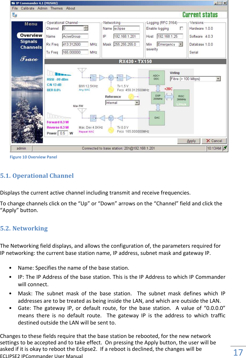
Commander User Manual
2.
User Manual
Commander User Manual
Navigation menu
Upload a User Manual
Namespaces
Wiki Guide
HTML
PDF
Info
Views
User Manual
Discussion / Help
Navigation