RF Technology E2-TRX500D UHF BASE STATION User Manual E2IPCommanderUserManual
RF Technology Pty Ltd UHF BASE STATION E2IPCommanderUserManual
Contents
- 1. Commander User Manual
- 2. User Manual
Commander User Manual

ECLIPSE2 IPCommander User
Eclipse2
IP Commander Software
User Manual
P
ublication Reference
23 November 2011
ECLIPSE2 IPCommander User
Manual
Eclipse2
IP Commander Software
User Manual
ublication Reference
– 0308920019
23 November 2011
1
IP Commander Software

ECLIPSE2 IPCommander User Manual
2
Disclaimer
Due to our policy of continuous improvement of our products and services, technical
specifications and claims that were correct at time going to print maybe subject to
variation without notice. RF Technology has endeavoured to ensure that the
information in this document is correct, but does not accept liability due to
typographical, omissions or other errors or subsequent modifications of the product.
Copyright
All information contained in this manual is the property of RF Technology Pty Ltd.
All rights are reserved. This manual may not, in whole or in part, be copied,
photocopied, reproduced, translated, stored, or reduced in any manner without
prior written permission.
All trade names referenced are the trademarks or registered trademarks of the
respective manufacturers.
RF Technology Pty Limited
Unit 46 / 7 Sefton Road
Thornleigh NSW 2120
Sydney Australia
Phone +61 2 9484 1022
Fax +61 2 9484 1288
Web www.rftechnology.com.au

ECLIPSE2 IPCommander User Manual
3
Contents
Contents ............................................................................................................................................ 3
1. Introduction ................................................................................................................................... 6
2. Getting Started .............................................................................................................................. 6
2.1. Connection ............................................................................................................................. 6
2.2. Default Login .......................................................................................................................... 8
2.3. Changing Admin Password ..................................................................................................... 8
2.4. Auto Login .............................................................................................................................. 9
3. Base Station Menu ...................................................................................................................... 10
3.1. Adding a Base Station Connection ....................................................................................... 10
3.2. Connecting to a Base Station ............................................................................................... 11
4. Admin Menu ................................................................................................................................ 12
4.1. Users ..................................................................................................................................... 12
4.2. Base Station Software .......................................................................................................... 13
4.3. Backup and Restore .............................................................................................................. 13
4.3.1. Backup ........................................................................................................................... 14
4.3.2. Restore .......................................................................................................................... 14
4.4. Check for Update .................................................................................................................. 14
4.5. Auto Check Updates ............................................................................................................. 14
4.6. Slow Connection ................................................................................................................... 15
4.7. Play Alarm Audio .................................................................................................................. 15
4.8. Reboot Base Station ............................................................................................................. 15
5. Overview ..................................................................................................................................... 16
5.1. Operational Channel ............................................................................................................ 17
5.2. Networking ........................................................................................................................... 17
5.3. Logging (Syslog) .................................................................................................................... 18
5.4. Versions ................................................................................................................................ 18
5.5. Exciter Transmit Power ........................................................................................................ 18
5.6. Reciter Temperature ............................................................................................................ 18
5.7. RX Path ................................................................................................................................. 18
5.8. RSSI ....................................................................................................................................... 19
5.9. C/N ........................................................................................................................................ 19
5.10. Channel Bandwidth ............................................................................................................ 19
5.11. RX P25 NAC ......................................................................................................................... 19
5.12. RX P25 BER ......................................................................................................................... 19

ECLIPSE2 IPCommander User Manual
4
5.12.1. RX VCO ......................................................................................................................... 19
5.13. TX Path ............................................................................................................................... 19
5.14. Forward Power ................................................................................................................... 19
5.15. Reverse Power .................................................................................................................... 19
5.16. Maximum Deviation ........................................................................................................... 20
5.17. TX VCO ................................................................................................................................ 20
5.18. TX P25 NAC ......................................................................................................................... 20
5.19. Voting ................................................................................................................................. 20
6. Signals .......................................................................................................................................... 22
6.1. Using the Signal Map ............................................................................................................ 22
6.2. Function Blocks..................................................................................................................... 24
6.2.1. FM Demodulator ........................................................................................................... 24
6.2.2. FM Modulator ............................................................................................................... 24
6.2.3. Tone Decoder ................................................................................................................ 25
6.2.4. Tone Encoder................................................................................................................. 25
6.2.5. De-Emphasis .................................................................................................................. 25
6.2.6. Pre-Emphasis ................................................................................................................. 26
6.2.7. Line Input ....................................................................................................................... 26
6.2.8. Line Ouput ..................................................................................................................... 26
6.2.9. Gain ............................................................................................................................... 26
6.2.10. Phase Invert ................................................................................................................. 27
6.2.11. Speaker ........................................................................................................................ 27
6.2.12. Microphone ................................................................................................................. 27
6.2.13. Voice Reporting ........................................................................................................... 27
6.2.14. Tone Generator ........................................................................................................... 28
6.2.15. Signal Mix .................................................................................................................... 28
6.2.16. Priority ......................................................................................................................... 28
6.2.17. Notch Filter .................................................................................................................. 28
6.2.18. High Pass Filter ............................................................................................................ 28
6.2.19. Low Pass Filter (LPF) .................................................................................................... 29
6.2.20. Pass Filter (BPF) ........................................................................................................... 29
6.2.21. Band Stop Filter (BSF) .................................................................................................. 29
6.2.22. APCO P25 Demodulator .............................................................................................. 29
6.2.23. APCO P25 Modulator .................................................................................................. 29
6.2.24. Talkgroup Out (VoIP/RoIP) .......................................................................................... 30

ECLIPSE2 IPCommander User Manual
5
6.2.25. Talkgroup IN (VoIP/RoIP) ............................................................................................. 30
6.2.26. Multi-Tone Decoder .................................................................................................... 31
6.2.27. Multi-Tone Encoder ..................................................................................................... 31
6.2.28. Continuous Wave Identification .................................................................................. 32
7. Channels ...................................................................................................................................... 35
7.1. Overview .............................................................................................................................. 36
7.2. FM & P25 RX Profile ............................................................................................................. 36
7.3. FM & P25 TX Profile .............................................................................................................. 36
7.4. RX Subaudio .......................................................................................................................... 37
7.5. TX Subaudio .......................................................................................................................... 37
7.6. RX Mute/RSSI........................................................................................................................ 37
7.7. RX P25 ................................................................................................................................... 37
7.8. TX P25 ................................................................................................................................... 37
7.9. TX P25 ................................................................................................................................... 38
7.10. TX CWID .............................................................................................................................. 38
7.11. Trace ................................................................................................................................... 38
8. Calibration ................................................................................................................................... 40
8.1. Codec calibration .................................................................................................................. 40
8.2. Output power calibration ..................................................................................................... 40
8.3. RSSI calibration ..................................................................................................................... 41
9. SNMP ........................................................................................................................................... 42

ECLIPSE2 IPCommander User Manual
6
1. Introduction
The Eclipse2 series product range is a radio platform that provides an
array of features and applications.
The IP Commander software is used to monitor and configure a range of parameters,
within the Eclipse2 Transceiver Modules, via the local USB port or remotely using the
Internet Protocol over Ethernet.
IP Commander is a platform independent application, written in Java®, and will run on
many operating systems, including all versions of Microsoft® Windows, Apple® MAC OS
and Linux.
IP Commander can additionally calibrate and update the Eclipse2 Transceiver Module
firmware via USB or remotely over Ethernet.
2. Getting Started
2.1. Connection
To physically connect the computer running IP Commander to the Eclipse2
Transceiver Module, use the front mounted USB connector or the rear mounted
Ethernet socket.
A standard “Type A” USB cable or RJ45 terminated Ethernet cable is required to
connect to the Eclipse2 Transceiver module.
Note that the USB connection is not supported under Microsoft Vista®.
The Eclipse2 has a preconfigured IP address of 192.168.1.201, however customers can
specify their own IP addresses at time of order.
Ensure that the computer, on which IP commander is running, is on the same IP
network as the Transceiver Module. The network mask will be 192.168.1.XXX when
using the Transceiver Module’s default IP address.
If you are unable to connect via the Ethernet connection or if the IP Address is unknown,
you can still connect by using the front panel mounted USB port. The IP Address can be
reset to a value of 192.168.1.201 by simultaneously pressing, and holding, the front
panel speaker and microphones PTT buttons, for five seconds.
NOTE: The IP Address reset sequence will not work if the front panel is
disabled.

ECLIPSE2 IPCommander User
Manual
Figure
1
Base station front an
Manual
Base station front an
d rear views
7
ECLIPSE2 IPCommander User Manual
8
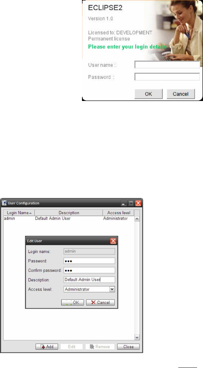
2.2. Default Login
Start IP Commander by clicking on the desktop icon and log in using the
following user name and password and click “OK”
Default User Name: admin
Default Password: rft
NOTE: The logon screen will not
be displayed if “Auto
Logon” is enabled.
NOTE: The user name and
password are case
sensitive.
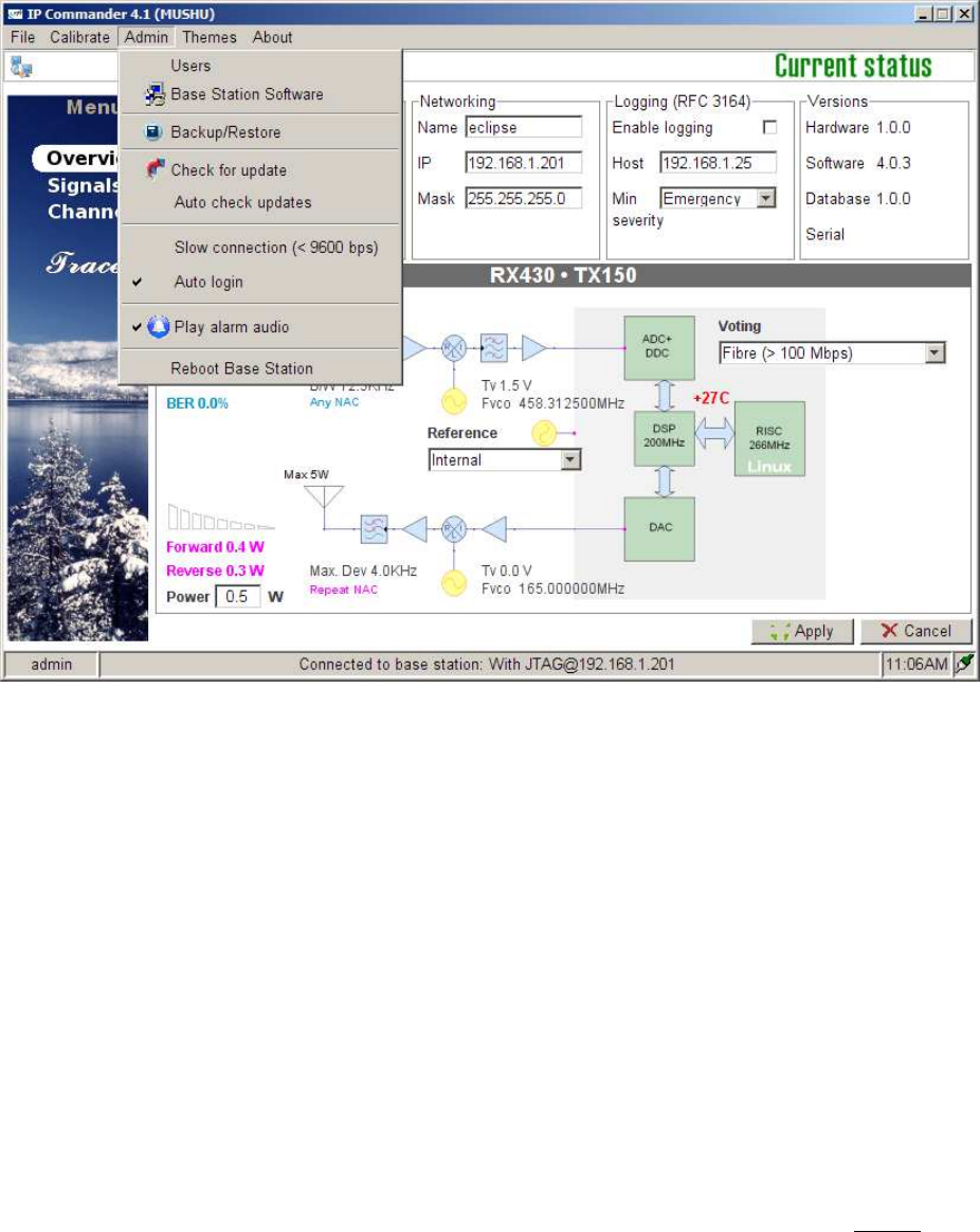
2.3. Changing Admin Password
To change the administrator password:
1. Select “Admin” from the main menu bar.
2. Select “Users”.
3. Select “admin” from the list and click “Edit”.
4. Enter and confirm your new password and click “OK”
Figure
2
Login screen
Figure
3
Changing Administrator Password
ECLIPSE2 IPCommander User Manual
9
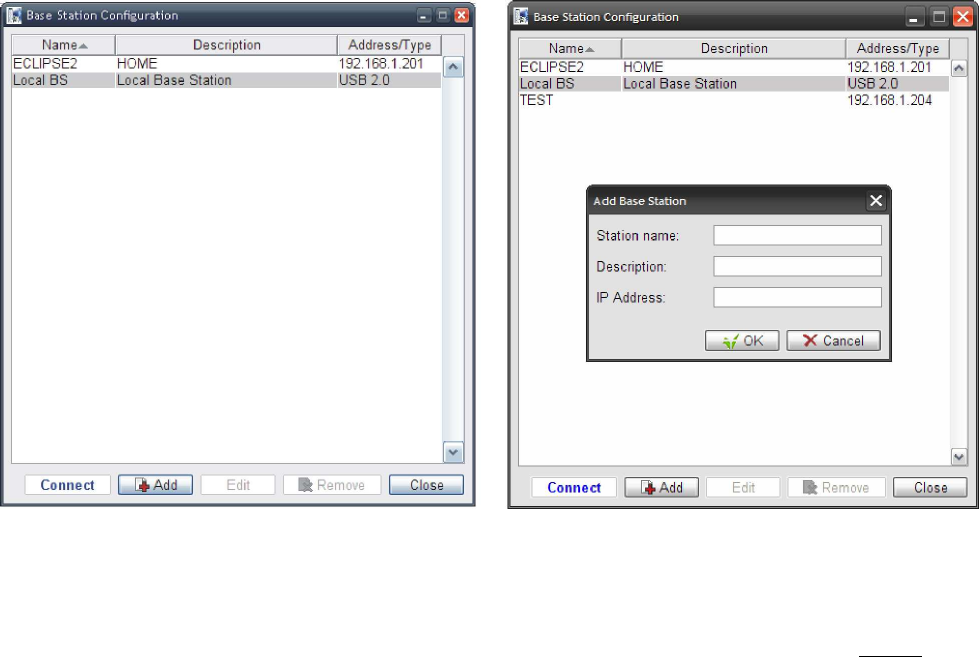
2.4. Auto Login
IP Commander can be setup to auto login, without requiring a username and password.
To enable Auto Login select “Admin” from the toolbar and click “Auto Login”
NOTE: Auto Login is enabled by default. If you upgrade IP Commander, you will
need to turn Auto Login off after the upgrade is complete.
Figure
4
Auto Login
ECLIPSE2 IPCommander User Manual
10
3. Base Station Menu
The Base Station Menu stores a list of base stations, to which IP Commander may be
connected.
3.1. Adding a Base Station Connection
To configure a base station connection, select from the main toolbar “File” then
select “Base Stations”
There are two default entries in the table:
• Eclipse2 default IP Address 192.168.1.201
• Local Base Station using the USB Port
Any entry can be added or removed from the list except for the Local USB Port.
NOTE: The USB Port is always present and cannot be removed.
To add a base station to the connection list, click “Add” and then enter a station
name, a description and the valid IP address of the base station.
An existing entry can also be edited or removed from the list.
Figure 5 Adding a Base Station Configuration
ECLIPSE2 IPCommander User Manual
11
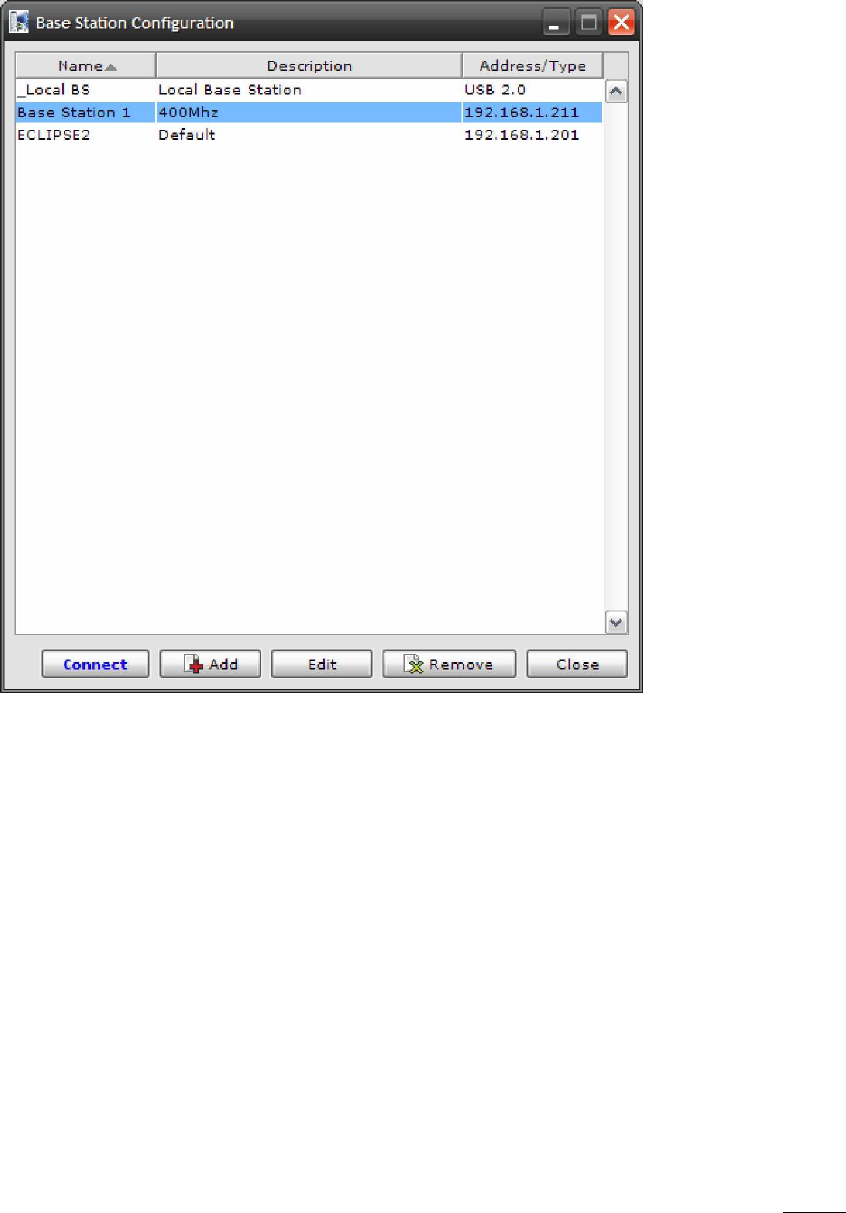
3.2. Connecting to a Base Station
To connect to a base station, double click an entry in the list or highlight an entry
and click “Connect”.
Figure 6 Connecting to a Base Station
ECLIPSE2 IPCommander User Manual
12
4. Admin Menu
The Admin menu allows you to:
• Add or remove users
• Upgrade and rollback Base Station software
• Backup and restore a snapshot of the base station configuration and software.
• Check for Software Updates via the RF Technology website
• Reboot the currently selected Base Station
• Select “Slow Connection <9600bps” speed
• Enable “Alarm Audio”
• Enable “Auto Login”
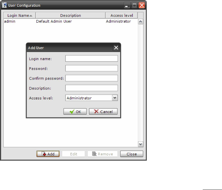
4.1. Users
The User Configuration menu allows you to add, delete or edit additional users from
the table.
NOTE: There must be at least one entry in the list with the access level set to
Administrator.
Figure
7
User Configuration Menu
ECLIPSE2 IPCommander User Manual
13
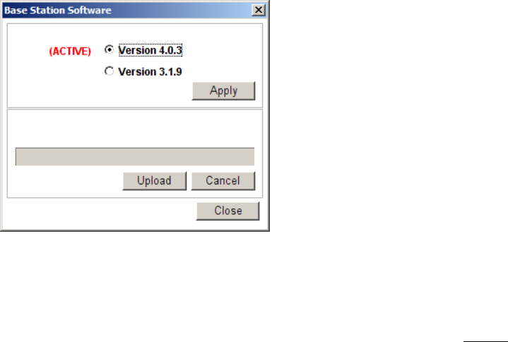
4.2. Base Station Software
IP Commander can perform an update or rollback of the base station software.
The Eclipse2 contains two copies of the firmware image, one active and one
inactive. During a software upgrade, the new version is copied to the inactive
memory location, only becoming active after a successful installation. If an
upgrade is interrupted, the original firmware will continue to be active.
The software upgrade is carried out using the local USB port or remotely using the
Ethernet connection.
The firmware files are supplied with a filename in the following format:
• firmware_1_8_0.esw
The filename determines the version number; in the above example, the Version number
is 1.8.0 and the file extension .esw indicates that it is an Eclipse2 software file.
To upload a new firmware file click “Upload” and select the firmware file and click “Apply”.
Once the upload has been completed, the base station will save the current base
station configuration and deploy the new firmware image.
When the new firmware has been deployed, click “OK” to reboot the base station.
During the reboot process, the base station will make the new firmware active and
load the configuration, which was automatically saved from the previous firmware.
A firmware update will take approximately two minutes to complete.
To rollback the firmware back to the previous version, select the inactive version and click
“Apply”.
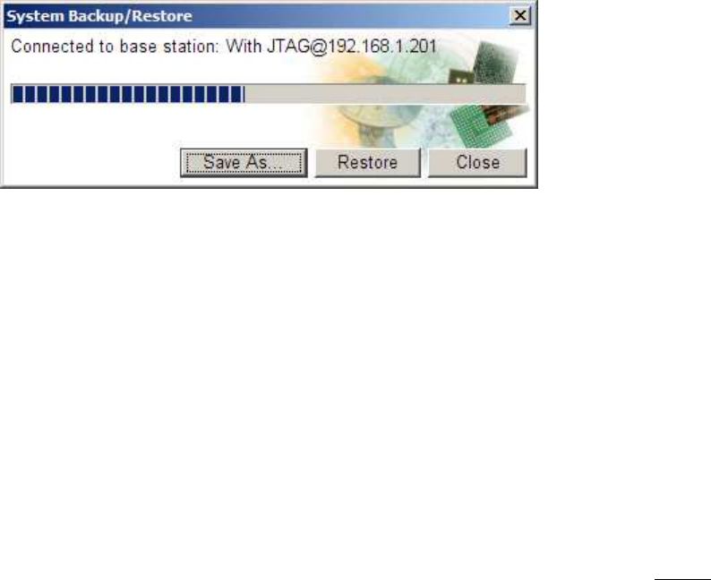
4.3. Backup and Restore
This process allows the saving and restoration of the base station non-volatile configuration
Figure 8 Base Station Software Upload
ECLIPSE2 IPCommander User Manual
14
data, including the signal map and channel profiles.
4.3.1. Backup
To start the Backup process select “Backup/Restore” from the Admin menu, then type a
filename for the backup file. Click “Save” and the backup process will start.
The backup process will take approximately two minutes to complete.
The backup file will have a default format of “base_station_name@xxx.xxx.xxx.xxx.ebs”
• Where base_station_name is the text from the networking name field
• xxx.xxx.xxx.xxx is the IP Address of the base station.
• .ebs is the file extension of the backup file.
However, the Backup file can be changed to any name provided the file extension remains
as .ebs
4.3.2. Restore
To start the Restore process select “Backup/Restore” from the Admin menu, then
select a previously saved backup file, click “Open” and the Restore process will start.
The restore process will take approximately two minutes to complete.
4.4. Check for Update
Select “Check for Update” to make IP Commander to immediately check for any software
updates via the internet.
This function is currently not implemented.
4.5. Auto Check Updates
This selection allows IP Commander to check automatically for any software updates via the
internet.
This function is currently not implemented.
Figure
9
Base Station Configuration
Restore

ECLIPSE2 IPCommander User Manual
15
4.6. Slow Connection
This selection adjusts IP Commander’s response time to suit slow speed networks.
Only enable this selection for IP networks that have a data rate of 9600bps or less.
4.7. Play Alarm Audio
If enabled, IP Commander will play an “Alarm” sound in a response to an alarm message
sent from the base station. The alarm will be played through the speakers connected to the
computer. The alarm sound can be customised by replacing the file “C:\Program
Files\IPCommander\wav\alarm.wav” with a sound file of your choosing. This
WAVE sound file will be repeatedly played during an alarm condition.
4.8. Reboot Base Station
Clicking on “Reboot Base Station” will send a command to restart the Reciter Module.

ECLIPSE2 IPCommander User Manual
16
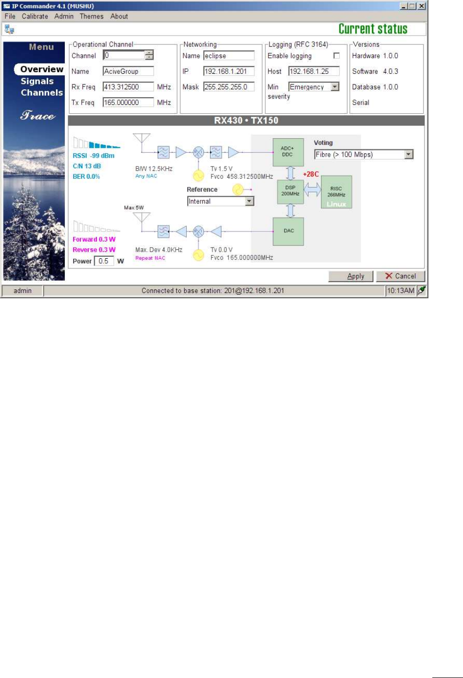
5. Overview
Once a connection with a base station has been established, the overview panel will display
the following information:
• Operational Channel including Name and Transmit/Receive frequencies.
• Networking Information including Name, IP address and subnet mask.
• System Logging including IP address and message type.
• Software, Hardware and Database Versions
• Temperature
• Receive Signal Level (RSSI) in dBm
• RF Carrier to Noise Ratio (C/N) in dB
• Exciter Transmit Power level
• Transmit Forward and Reverse Power levels
• Transmit and Receive VCO Tuning Voltage
• Reference Frequency
• P25 NAC Codes
• P25 BER
• In-base voting
ECLIPSE2 IPCommander User Manual
17
5.1. Operational Channel
Displays the current active channel including transmit and receive frequencies.
To change channels click on the “Up” or “Down” arrows on the “Channel” field and click the
“Apply” button.
5.2. Networking
The Networking field displays, and allows the configuration of, the parameters required for
IP networking: the current base station name, IP address, subnet mask and gateway IP.
• Name: Specifies the name of the base station.
• IP: The IP Address of the base station. This is the IP Address to which IP Commander
will connect.
• Mask: The subnet mask of the base station. The subnet mask defines which IP
addresses are to be treated as being inside the LAN, and which are outside the LAN.
• Gate: The gateway IP, or default route, for the base station. A value of “0.0.0.0”
means there is no default route. The gateway IP is the address to which traffic
destined outside the LAN will be sent to.
Changes to these fields require that the base station be rebooted, for the new network
settings to be accepted and to take effect. On pressing the Apply button, the user will be
asked if it is okay to reboot the Eclipse2. If a reboot is declined, the changes will be
Figure
10
Overview Panel

ECLIPSE2 IPCommander User Manual
18
discarded and the current settings retained.
5.3. Logging (Syslog)
The Eclipse2 has a built-in Syslog client conforming to the RFC3164 protocol.
When enabled the Eclipse2 will send messages to a Syslog Server or Host using a
specified IP address and severity level.
• Enable Logging: Click on check box to enable logging.
• Host: Enter the IP address of the Syslog Server that will receive the messages.
• Min Severity: Specifies the level of the message type.
There are eight message types:
Level 0. Emergency
Level 1. Alert
Level 2. Critical
Level 3. Error
Level 4. Warning
Level 5. Notice
Level 6. Informational
Level 7. Debug
5.4. Versions
Displays the current software, hardware and database version numbers.
5.5. Exciter Transmit Power
Displays the current Exciter RF Power Output in Watts.
The Exciter has an RF power output of 0.1 watt to 5 watts, set via the Power field.
To change the Exciter TX power, enter the required power level and click the “Apply”
button. Valid power levels are from 0.1 to 5 watts in 0.1 watt increments.
5.6. Reciter Temperature
Displays the current free air temperature inside the reciter module.
5.7. RX Path

ECLIPSE2 IPCommander User Manual
19
When receiving a valid analog signal the RX path will be highlighted in green. Blue
highlighting indicates a valid P25 signal.
5.8. RSSI
Displays the Received Signal Strength in dBm.
5.9. C/N
Displays the current RF Carrier to Noise Ratio in dB.
5.10. Channel Bandwidth
Displays the current channel bandwidth. 12.5KHz or 25KHz.
5.11. RX P25 NAC
Displays the current decoded RX NAC.
Only displayed when the C4FM demodulator is present on the signal map.
5.12. RX P25 BER
Displays the Bit Error Rate of the P25 Demodulator.
Only displayed when the P25 demodulator is present on the signal map.
5.12.1. RX VCO
Shows current RX VCO tuning voltage and PLL frequency.
5.13. TX Path
When transmitting an analog signal, the TX path will be highlighted in orange. Pink
highlighting means a P25 signal is being transmitted.
5.14. Forward Power
Displays the forward power at the Exciter output.
5.15. Reverse Power
Displays the reverse power at the Exciter output.

ECLIPSE2 IPCommander User Manual
20
5.16. Maximum Deviation
Displays the maximum transmitter deviation for the current channel.
Typical maximum deviation values are 2.5KHz for Narrowband channels and 5KHz for
wideband channels.
5.17. TX VCO
Shows the current TX VCO tuning voltage and PLL frequency.
5.18. TX P25 NAC
Displays the current TX NAC.
Only displayed when the C4FM modulator is present on the signal map.
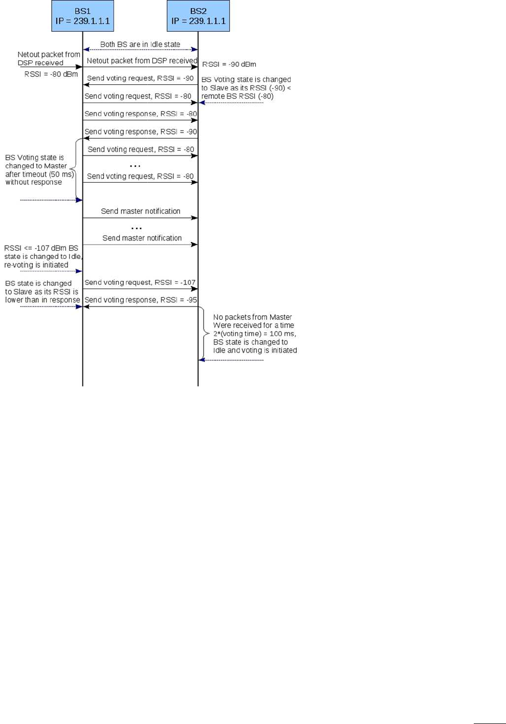
5.19. Voting
In-base voting is used to determine the base station with the best incoming signal, and to pass the
signal from that base station to other bases.
It is recommended that base stations be part of same IP multicast group.
When the base stations are receiving, they send their RSSI values to each other. One of the base
stations will determine that it has the highest RSSI value, become the master base station and then
inform all the other base stations that they are slaves.
The slave base stations will listen for audio packets from the master base station, for the duration of
the call, until the following conditions arise:
1. The master’s RSSI value falls below -107dbm, in which case a new master base station will
be assigned
2. All the base stations stop receiving, which will invoke a restart of the voting process
3. The master base station stops receiving and a new master is assigned
Base Stations can join or leave the multicast group without causing system failure. (no permanently
assigned master).
This type of voting architecture is distributed, thus no central voting comparator is required.
The Audio packets are sent only from the master to the slaves, the master base station transmitting
its own received audio locally.
The data rate of a stream is approximately 100Kbps using the G711 audio codec, thus only 100kbps
per base station is required.
Comparing the above distributed voting to the use a central voting comparator, for a central
comparator ALL audio packets are routed via the voter for processing. Since there are now separate
receive and transmit audio paths required per base station, the required data rate (and consequently
bandwidth) is doubled to 200kbps per base station.
ECLIPSE2 IPCommander User
Manual
Figure 11 Voting sequence
Manual
21
ECLIPSE2 IPCommander User Manual
22
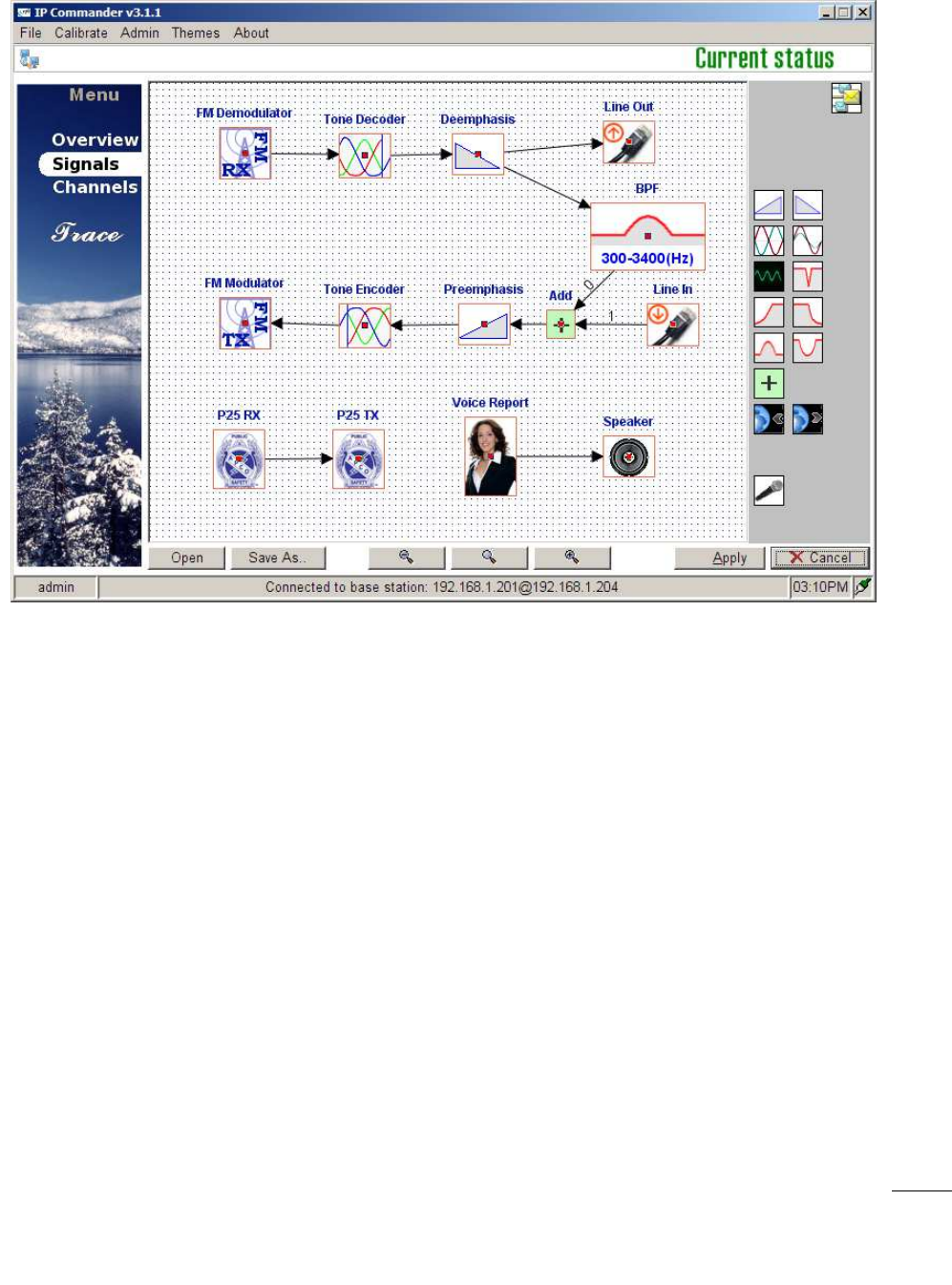
6. Signals
The Signals menu panel provides a visual tool with which to configure the Signal Map. Within
the signal map, various Function Blocks are placed and interconnected to set the required
base station controls and features. An example signal map is shown in Figure 12.
Figure 12 Signals Panel
6.1. Using the Signal Map
The Signal map configures the Eclipse2 by using various function blocks to form a base
station or repeater.
Configuring the signal map is carried out by using a drag and drop interface. To insert a
function, select an item using the mouse from the right side panel and drag it onto the
map.
To remove a function block from the map, right click the item and select “Remove”.
To connect the function blocks together click the small red square in the centre of one
function and drag a line to the next function down the chain.
Note: Function Blocks have directional inputs and outputs. Outputs can only be connected to inputs.
Some functions, like the FM Demodulator, have only an output. For example when drawing a
connecting line start at the FM Demodulator and drag it to the Tone Decoder, not the reverse.
If the Error message “Target Block does not have Input” is displayed, try drawing the
connection line in the reverse direction between the blocks.
ECLIPSE2 IPCommander User Manual
23
The output of each function block can be connected to the inputs of multiple function
blocks, to a maximum of ten. To do this, repeat the dragging operation, from the small red
square, for each desired output connection. Under these circumstances, the input to each
block is identical, the single output being simultaneously copied to each of the function
block inputs.
Signal Maps can also be saved to a file and reused to configure another base station. To
save a configuration click the “Save As” button and type a filename name and click “Save”. If
a configuration does not fit within the signal map window, use the Zoom Out or Zoom In
buttons to resize the window so that all the function blocks are visible. Should the
configuration be no longer visible, click the Zoom button to reset the Signal Map back to
its default magnification.
Function blocks have fixed properties and variable parameters, such as:
• Input Only
• Output Only
• Multiple Outputs / Multiple Inputs
• Audio Gain or Attenuation (dB)
• Frequency Response
• Priority or Signal Mix
• IP Address and/or Port Number (Unicast or Multicast)
Figure
1
3
Signal Map

ECLIPSE2 IPCommander User
Manual
Function Blocks available:
•
FM Analogue Modulator and Demodulator
• APCO P25
Modulator and Demodulator
•
CTCSS encode/decode and DCS (Digital Coded Squelch)
• De-emphasis and Pre
-
•
Line Audio gain control
•
Audio Filters (Low pass, High pass, Notch and Bandpass)
• Priority Control
•
EclipseNet IP Networking (TIA
• Voice Reporting
•
Audio Tone Generator
• Signal Path Mixer
6.2. Function Blocks
The Eclipse2 uses function blocks to allow
downloaded to the base station
Typical examples of these configurations are:
•
Repeater with CTCSS encode and decode.
•
Repeater with CTCSS encode/decode and 4Wire + E&M.
•
Base Station with 4Wire + E&M signalling and EclipseNet VoIP Networking.
•
Repeater with EclipseNet VoIP networking.
•
Dual Mode Analogue FM and APCO P25
6.2.1. FM Demodulator
The FM Demodulator provides the function
Standard Channel bandwidths
channel basis,
via the channel menu.
The output can connect to tone decoders, audio filters, de
EclipseNet VoIP Networking.
6.2.2. FM Modulator
The FM
Modulator provides the function
Manual
FM Analogue Modulator and Demodulator
Modulator and Demodulator
CTCSS encode/decode and DCS (Digital Coded Squelch)
-
emphasis
Line Audio gain control
Audio Filters (Low pass, High pass, Notch and Bandpass)
EclipseNet IP Networking (TIA
-102.BAHA AFSI/DFSI).
Audio Tone Generator
The Eclipse2 uses function blocks to allow
various configurations and options to be
downloaded to the base station
, as a predefined signal map.
Typical examples of these configurations are:
Repeater with CTCSS encode and decode.
Repeater with CTCSS encode/decode and 4Wire + E&M.
Base Station with 4Wire + E&M signalling and EclipseNet VoIP Networking.
Repeater with EclipseNet VoIP networking.
Dual Mode Analogue FM and APCO P25
The FM Demodulator provides the function
of
a standard FM analogue receiver.
Standard Channel bandwidths
of 12.5KHz and 25KHz are available,
configured on a per
via the channel menu.
The output can connect to tone decoders, audio filters, de
-
emphasis, line out and
Modulator provides the function
of a standard FM analogue
24
various configurations and options to be
Base Station with 4Wire + E&M signalling and EclipseNet VoIP Networking.
a standard FM analogue receiver.
configured on a per
emphasis, line out and

ECLIPSE2 IPCommander User Manual
25
transmitter. Maximum deviation setting is 10KHz in 1Hz steps.
Standard values are 2.5KHz deviation for 12.5KHz channel spacing and 5.0KHz deviation
for 25KHz channel spacing. These can be configured on a per channel basis, via channel
menu.
The input can connect to the output of the tone encoder, pre-emphasis, line in,
EclipseNet VoIP Networking and audio filters.
6.2.3. Tone Decoder
Provides CTCSS and DCS decoding. The output of this block is audio with the CTCSS tones
filtered out by a high pass filter with a 300Hz cut-off frequency.
The input connects from the FM Demodulator. Standard DCS/CTCSS EIA Tone set is used,
with tones in the frequency range 67.0Hz to 254.0Hz.
A typical configuration connects this block between the FM Demodulator and the De-
Emphasis and Audio Filters.
6.2.4. Tone Encoder
Provides CTCSS and DCS encoding.
Its output typically connects to the FM Modulator. This block uses the standard DCS/CTCSS
EIA Toneset, with frequencies ranging from 67.0Hz to 254.0Hz.
The deviation levels are set via the channel menu: 12.5KHz Channel = 250Hz and 25KHz
Channel = 500Hz. The CTCSS block supports Reverse Tone Burst and a programmable No
Tone Period, at the end of transmission, from 0 to 999ms, set via the channel menu.
A typical configuration has the encoder between the FM Modulator and the Pre-Emphasis
and Audio Filters.
6.2.5. De-Emphasis
Provides a standard FM Receiver de-emphasised audio response.
Required for standard FM analogue base station and repeater configurations. Connects between the
FM Demodulator and Audio Filters.

ECLIPSE2 IPCommander User Manual
26
6.2.6. Pre-Emphasis
Provides a standard FM Transmitter pre-emphasised audio response.
Required for standard base station and repeater configurations. Connects between the FM
Modulator and Audio Filters.
6.2.7. Line Input
The Line Input function connects the external 600 Ohm Balanced Line Input to the
transmit audio path.
The audio input is typically set for a level of -10dBm to achieve 60% of system deviation.
Use the Gain function block to adjust the audio levels for the required deviation as per the
following table.
Channel Bandwidth
Maximum Transmit
60% of Maximum
Deviation
Transmit
Deviation
12.5KHz narrowband
2.5KHz
1.5KHz
25KHz wideband
5.0KHz
3.0KHz
6.2.8. Line Ouput
The Line Output connects the external 600 Ohm Balanced Line Output to the receiver
audio path. Use the Gain function block to adjust the line audio levels as per the following
table.
Channel Bandwidth
60% of Deviation
Line Out Audio
with a 1KHz tone
Level
12.5KHz narrowband
1.5KHz
-
10dBm
25KHz wideband
3.0KHz
-
10dBm
6.2.9. Gain

ECLIPSE2 IPCommander User
Manual
The Gain function block has one input
attenuation or amplification for any audio signal.
Values range from +/-
40dB in steps of 0.1 dB.
As an example, using the Gain function allows the audio levels to be adjusted for the Line
In and Line Out audio ports.
6.2.10. Phase Invert
The Phase Invert block provides a 180 degree inversion of an audio signal.
Typically used for specialist applications to invert the phase of a FFSK signalling system.
6.2.11. Speaker
The Speaker function block allows any
mounted speaker.
Typical examples of using the Speaker function
•
Allows the Voice Reporting audio to playback through the local speaker.
•
Allows the monitoring of the receive and transmit audio paths.
• All
ows the monitoring of the Line Input and Output Audio Ports.
The Speaker audio level is adjusted by the use of the volume up / down buttons on the front
panel of the Reciter Module.
6.2.12. Microphone
The microphone function enables the front panel mounted
transmit or line audio paths.
6.2.13. Voice Reporting
Provides a voice report on the current base station status.
The output of the voice reporting can be routed to:
•
The transmit audio path to be transmitted to air.
• The
front panel Speaker (
Manual
The Gain function block has one input
and multiple outputs and provides audio level
attenuation or amplification for any audio signal.
40dB in steps of 0.1 dB.
As an example, using the Gain function allows the audio levels to be adjusted for the Line
The Phase Invert block provides a 180 degree inversion of an audio signal.
Typically used for specialist applications to invert the phase of a FFSK signalling system.
The Speaker function block allows any
audio signal to be routed to the local front
Typical examples of using the Speaker function
are:
Allows the Voice Reporting audio to playback through the local speaker.
Allows the monitoring of the receive and transmit audio paths.
ows the monitoring of the Line Input and Output Audio Ports.
The Speaker audio level is adjusted by the use of the volume up / down buttons on the front
The microphone function enables the front panel mounted
microphone to be routed to the
Provides a voice report on the current base station status.
The output of the voice reporting can be routed to:
The transmit audio path to be transmitted to air.
front panel Speaker (
use the Speaker Function block)
27
and multiple outputs and provides audio level
As an example, using the Gain function allows the audio levels to be adjusted for the Line
The Phase Invert block provides a 180 degree inversion of an audio signal.
Typically used for specialist applications to invert the phase of a FFSK signalling system.
audio signal to be routed to the local front
Allows the Voice Reporting audio to playback through the local speaker.
The Speaker audio level is adjusted by the use of the volume up / down buttons on the front
microphone to be routed to the

ECLIPSE2 IPCommander User Manual
28
• The Audio Line Output port.
The voice reporting can be used for providing the current channel information and any
alarms that are present and route them accordingly to the configuration of the signal map.
6.2.14. Tone Generator
The Tone generator function block allows audio signals to be generated within the base
station for testing purposes or specific applications such as a receive status tone generator
for Sinad Voters.
The frequency range is 1 to 3400Hz, in 1Hz increments.
Audio level adjustment is achieved by connecting the output to the Gain function block.
6.2.15. Signal Mix
The Add function combines or mixes two audio or signal paths together. More than two
inputs can be mixed together by cascading Add functions.
6.2.16. Priority
The Priority function allows two audio signal paths to be combined with one signal having a
priority over another. Input number “0” will have the highest priority, while input number
“1” will have the lowest priority.
The priority function can also be placed on the input to the P25 modulator, and used to
prioritise between the output of the P25 demodulator and the P25 stream coming from the
Talkgroup IN function, which decodes DFSI from the network.
6.2.17. Notch Filter
The notch filter frequency can be set from 200Hz to 3000Hz.
6.2.18. High Pass Filter

ECLIPSE2 IPCommander User
Manual
The HPF filter function is specified by setting the pass frequency
kHz.
6.2.19. Low Pass Filter (LPF)
The LPF filter function is specified by setting the cuttoff frequency value from 100Hz to 3.4
kHz.
6.2.20. Pass Filter (BPF)
IP Commander will combine the lowpass filter and the highpass filter to form
filter. The frequency range is from 100Hz to 3.4KHz
6.2.21.
Band Stop Filter (BSF)
IP Commander will combine the lowpass filter and the highpass filter to form a
bandstop filter The frequency range is from 100Hz to 3.4KHz
6.2.22.
APCO P25 Demodulator
The P25
demodulator provides the function for an APCO P25 Receiver.
Available channel bandwidths are 12.5KHz and 25KHz.
It us
es NAC codes to determine channel access.
The demodulator can receive P25 voice and data messages, as well as Trunking
Blocks (TSBKs).
6.2.23. APCO P25 Modulator
The P25 modulator provid
es the function for an APCO P25
Transmitter. It s
upports C4FM deviation scale from 90% to 110%
For maintenance purposes,
the P25 modulator has the ability to generate
the P25 STD
1011 and high deviation patterns
patterns by using the transmitter’s C4FM tab within the “Channel” panel
Manual
The HPF filter function is specified by setting the pass frequency
value from 200Hz to 3.4
The LPF filter function is specified by setting the cuttoff frequency value from 100Hz to 3.4
IP Commander will combine the lowpass filter and the highpass filter to form
filter. The frequency range is from 100Hz to 3.4KHz
Band Stop Filter (BSF)
IP Commander will combine the lowpass filter and the highpass filter to form a
bandstop filter The frequency range is from 100Hz to 3.4KHz
APCO P25 Demodulator
demodulator provides the function for an APCO P25 Receiver.
Available channel bandwidths are 12.5KHz and 25KHz.
es NAC codes to determine channel access.
The demodulator can receive P25 voice and data messages, as well as Trunking
es the function for an APCO P25
upports C4FM deviation scale from 90% to 110%
the P25 modulator has the ability to generate
1011 and high deviation patterns
built-in. Activate these
patterns by using the transmitter’s C4FM tab within the “Channel” panel
29
value from 200Hz to 3.4
The LPF filter function is specified by setting the cuttoff frequency value from 100Hz to 3.4
IP Commander will combine the lowpass filter and the highpass filter to form
a bandpass
IP Commander will combine the lowpass filter and the highpass filter to form a
The demodulator can receive P25 voice and data messages, as well as Trunking
Signalling
the P25 modulator has the ability to generate

ECLIPSE2 IPCommander User Manual
30
of IP Conmmander. When these patterns are activated, the transmitter
will immediately key up and start transmitting.
The TX NAC code is set via the channel menu.
The modulator can send P25 voice and data messages, as well as Trunking Signalling Blocks
(TSBKs).
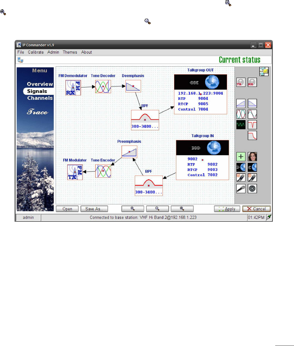
6.2.24. Talkgroup Out (VoIP/RoIP)
Using the Talkgroup Out function enables EclipseNet functionality as per TIA-102.BAHA
APCO P25 DFSI/AFSI. DFSI will be enabled when the Talkgroup In function is driven by a P25
block, and AFSI will be enabled when driven by a PCM/analog block.
To enable Multicast VoIP operation, drag the Talkgroup Out function block onto the signal
map, right click, select “Edit”, enter a valid IP address and port number. Multicast IP
addresses are in the range of 224.0.0.0 to 239.255.255.255.
Multicast Port Numbers for RTP have a default of 9000 and if changed must be an even
number eg: 9000, 9002, 9004, 9006 etc.
To enable Unicast VoIP operation, drag the Talkgroup Out function block onto the signal
map, right click, select “Edit”, enter a valid IP address and port number. Unicast IP
addresses for private WAN or LAN networks are in the range of:
10.0.0.0 – 10.255.255.255
172.16.0.0 – 172.31.255.255
192.168.0.0 – 192.168.255.255
Unicast Port Numbers use the following formats:
• RTP: must be an even number starting from 9000 eg: 9000, 9002, 9004 etc.
• RTCP: The RTCP port number is automatically set. The port number is an odd
number and is always higher in value by one than the RTP port. For example if the
RTP port is 9002 then the RTCP port will be automatically set to 9003.
• Control: The Control port number is automatically defined by the RTP port minus
2000. For Example if the RTP port is 9004, then the Control port will be set to
7004.
For detailed configuration on EclipseNet consult the Eclipse2 Application Guide.
6.2.25. Talkgroup IN (VoIP/RoIP)
Using the Talkgroup In function enables EclipseNet functionality as per TIA-102.BAHA

ECLIPSE2 IPCommander User Manual
31
DFSI/AFSI. DFSI will be enabled when the Talkgroup In function is driving a P25 block, and
AFSI will be enabled when driving a PCM/analog block.
To setup Talkgroup In, drag the function block onto the signal map, right click, select
“Edit” and enter a valid port number, corresponding to an appropriate Talkgroup Out RTP
port number, for Unicast, or a valid IP address and port number, for Multicast.
For detailed configuration on EclipseNet consult the Eclipse2 Application Guide.
6.2.26. Multi-Tone Decoder
Provides CTCSS and DCS decoding. The output of this block is audio with the CTCSS/DCS
tones filtered out by a high pass filter, with a 300Hz cut-off frequency. The output is active
only when the corresponding CTCSS/DCS signal is detected at the input.
A standard DCS/CTCSS EIA Tone set is used, with tones in the frequency range 67.0Hz to
254.0Hz. The frequency of the decoder is set by editing the icon on the signal graph.
Instantiate one multi-tone decoder for each frequency to be decoded, setting each instance
to a different frequency. Up to ten different frequencies may be decoded.
A typical configuration connects this block after the FM Demodulator, the output of the
demodulator being connected in a parallel configuration to the input of each decoder. The
output of each decoder may be processed independently, or summed and fed into a
common signal path.
6.2.27. Multi-Tone Encoder
Provides CTCSS and DCS encoding.
This block uses the standard DCS/CTCSS EIA Toneset, with frequencies ranging from 67.0Hz
to 254.0Hz. The frequency of the encoder is set by editing the icon on the signal graph.
Instantiate one multi-tone encoder for each frequency to be encoded, setting each instance
to a different frequency. Up to ten different frequencies may be encoded.
The deviation levels are set via the channel menu: 12.5KHz Channel = 250Hz and 25KHz
Channel = 500Hz. The CTCSS block supports Reverse Tone Burst and a programmable No
Tone Period, at the end of transmission, from 0 to 999ms, set via the channel menu.
A typical configuration connects this block before the FM Modulator. The encoder output
for each frequency should be summed and fed into the modulator. The input of each
encoder may be from an independent signal path, or a single path may be split and
connected to the encoder inputs, in parallel.

ECLIPSE2 IPCommander User Manual
32
6.2.28. Continuous Wave Identification
This block periodically inserts a Morse code identifier into an audio stream. It has one input
and one output. The input is the audio stream into which the identifier is to be inserted.
The output is the audio stream, with the identifier inserted. The period between identifiers,
the speed of the Morse Code, the frequency of the CW tone and the message being sent are
set in the transmitter profile, on a per channel basis. Further details are in section 7.10.
The CWID block will only insert audio when the incoming audio stream is inactive, meaning
the identifier will never interrupt a call. If the audio is active when the next identifier is due,
the identifier will be sent at the first opportunity, after the audio becomes idle. If the
transmission of an identifier is interrupted by a call, it will be retransmitted at the first
opportunity, until it has been sent in its entirety.
If the identifier is to be override a call, leave the input to the CWID block disconnected, and
use either a priority or addition block to mix the output of the CWID block into the audio
stream.
The CWID Block uses the International Morse Code, as in Table 1.
Table 1: CWID Morse code alphabet
Character
Code Character
Code Character
Code Character
Code
A .- N -. 0 ----- ‘ .----.
B -... O --- 1 .---- ( -.--.
C -.-. P .--. 2 ..--- ) -.--.-
D -.. Q --.- 3 ...-- + .-.-.
E . R .-. 4 ....- , --..--
F ..-. S ... 5 ..... - -....-
G --. T - 6 -.... . .-.-.-
H .... U ..- 7 --... / -..-.
I .. V ...- 8 ---.. : ---...
J .--- W .-- 9 ----. ; -.-.-.
K -.- X -..- ! -.-.-- = -...-
L .-.. Y -.-- “ .-..-. ? ..--..
M -- Z --.. $ ...-..- @ .--.-.
& .-... _ ..--.-
6.2.29. Digital Input/Output
This block generates a verbal announcement in response to an external digital input. It has a
single output, which is active whenever the alarm message is being spoken. The message

ECLIPSE2 IPCommander User Manual
33
will be periodically repeated, for as long as the input remains active. The external input
which is used as the trigger, the polarity of the external input, the text of the message and
the repetition period of the alarm message are all programmable. Optionally, the external
input can also be used to active an alarm within the Eclispe2’s alarm subsystem. This “User
Defined” alarm will generate warnings and an SNMP trap, like any other alarm in the
Eclipse2. Up to two digital I/O blocks may be instantiated.
A list of the external inputs which may be monitored, along with their mnemonics, is given in
Table 2. The mnemonic is the text which is to be entered in the “pin” field of the I/O block,
causing the corresponding pin to be monitored.
Table 2: External inputs which may be monitored
Mnemonic Function
RXPLL RX PLL locked
TXPLL TX PLL locked
FPUP “Up” button on front panel
FPRIGHT “Right” button on front panel
FPDOWN “Down” button on front panel
FPLEFT “Left” button on front panel
FPSTATUS “Status” button on front panel
FPPTT “PTT” button on front panel
MICPTT Microphone PTT input
EMPTT E&M PTT input
TTLPTT TTL PTT from backplane
EXTSQ External squelch input
GPI General Purpose Input from backplane
GPIO pins can also be monitored by specifying a register name and bit position. Such labels
are of the form “rNN”, where “r” is a letter in the range A to D and “nn” is a number in the
range zero to 31. The mapping of GPIO bit positions to functions is not guaranteed to be
constant, so the mnemonics of Table 2 are preferred.
The “state” field specifies whether the high or low state of the input being monitored is to
be considered asserted. The message will be spoken while the input is asserted.
The “text” field contains the text of the message to be spoken. It may contain alphanumeric
characters and spaces. The Eclipse2 system will convert this text into spoken word, using an
in-built speech synthesiser. If the text field is left blank, the audio output of the I/O block
will be disabled. Any audio from the Eclipse2 alarm system will not be disabled.
The “period” field specifies how often the message will be repeated. The message will be
periodically repeated, until the input being monitored becomes unasserted.
The “alarm” field specifies whether an asserted input is to trigger an alarm within the
Eclipse2. A zero in this field means an alarm will not be generated. A value of one means an
alarm will be generated when the external input is asserted. The generated alarm is labelled
“User Defined” in the Eclipse2 alarm system. Like any other alarm, the “User Defined” may
be monitored via SNMP, IP Commander or audio. If multiple IO blocks are instantiated, an

ECLIPSE2 IPCommander User Manual
34
alarm is generated by the logical OR, of the state of each IO block that has alarming enabled.
ECLIPSE2 IPCommander User Manual
35
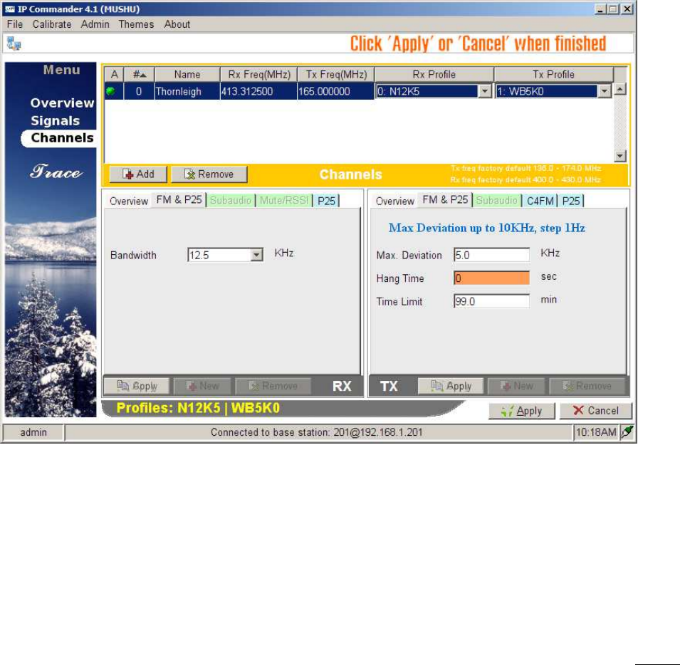
7. Channels
The Channel menu configures the following fields:
• Transmit and Receive Frequencies
• CTCSS and DCS encode and decode tones
• Channel Name
• Channel Number (max 256 Channels)
• Channel Bandwidth (12.5KHz or 25KHz)
• Mute Settings
• P25 NAC codes
• Profile Name and Number (max 256 Profiles)
The each channel in the menu is treated as a profile for the signal graph, as defined in the
signals panel.
A channel be dual mode by adding both FM and APCO P25 functions, in parallel, to the same
signal graph.
When editing a profile, certain options are not selectable until the function is added to the
signal map.
The availability of the following options in the profile table will depend on the existence
Figure 14 Channels Panel

ECLIPSE2 IPCommander User Manual
36
of the appropriate function block on the signal map.
• FM Modulator
• FM Demodulator
• Tone Encoder (CTCSS & DCS)
• Tone Decoder (CTCSS & DCS)
• P25 Modulator (APCO P25)
• P25 Demodulator (APCO P25)
For example, placing the tone decoder block into the signal map will enable the Subaudio
panel in RX profile.
Each channel is effectively a stored profile. Each entry in the channel table has an
associated channel number, a transmit frequency, a receive frequency and a reference
profile number.
To edit the channel name or frequencies double click the appropriate field, make any
appropriate changes and click the “Apply” button.
To make any channel active double click the leftmost column in the channel table and
click the “Apply” button.
A channel entry in the table will have a green icon displayed indicating that it is currently
active.
7.1. Overview
The Overview tab, within the channel panel, displays the profile number and name,
channel bandwidth and CTCSS tones. Every entry in the table has separate RX and TX
profiles.
The Eclipse2 can store up to 256 Profiles and 256 Channel Numbers.
7.2. FM & P25 RX Profile
Sets the channel bandwidth. Values are 12.5KHz or 25KHz.
7.3. FM & P25 TX Profile
Configures the following fields:
• Maximum Deviation
• Transmitter Hang Time from 0.1 to 99 seconds

ECLIPSE2 IPCommander User Manual
37
• Transmit Limit Timer from 0 to 999 minutes
7.4. RX Subaudio
The RX Subaudio tab defines the CTCSS or DCS tone for the current profile.
7.5. TX Subaudio
The TX Subaudio tab defines the following fields:
• CTCSS or DCS tone.
• CTCSS Deviation
• DCS Deviation
• DCS Invert Enable
• No Tone Period
• Enable Reverse Tone Burst
7.6. RX Mute/RSSI
The Mute/RSSI Tab stores the mute settings for the receiver. The mute state can be
determined either by the signal strength in dBm or the carrier to noise ratio in dB. Typically,
the RSSI Hysteresis will be set in the range 2-4dB, and both C/N and C/N Hysteresis will be
set to zero.
7.7. RX P25
Conventional APCO P25 systems use a Network Access Code (NAC).
The Rx profile (P25 Tab) allows user to specify whether the base station shall accept a P25
call with any NAC or with a user specified NAC, thus restricting radio network access.
Three specific NAC codes are set aside for the following functions:
• 293 – Default NAC
• F7E – The receiver will unmute on any NAC
• F7F – This will cause the transmitter to set its NAC from the received NAC.
7.8. TX P25
The TX C4FM modem can be configured to transmit a STD DEV or STD 1011 patterns for
servicing and testing purposes.
Deviation scale allows user to adjust the deviation in a range from 90% to 110% from the
normal setting of 100%.
ECLIPSE2 IPCommander User Manual
38
7.9. TX P25
The TX P25 tab allows the user to choose whether to repeat the incoming NAC or override
with a user defined TX NAC code.
7.10. TX CWID
The TX CWID tab allows the user to set the period between CWID identifiers, the speed
of the Morse Code, the frequency of the CW tone used and the message being sent.
The ID field is used to set the Morse code message to be transmitted. It can be up to
20 characters in length, and contain the characters A-Z, 0-9 and the punctuation
characters shown in Table 1. Lower case letters will be converted to upper case.
The Tone field sets the frequency of the tone used to transmit the Morse code, in units
of hertz.
The Morse Speed field controls the speed at which the Morse code is transmitted. It is
in units of words per minute, where the word being transmitted is PARIS.
The TX Interval field controls the period between each CWID identifier. It is in units of
seconds, and may take a value up to 9999 seconds.
A detailed description, of the operation of the CWID block, is in section 6.2.28.
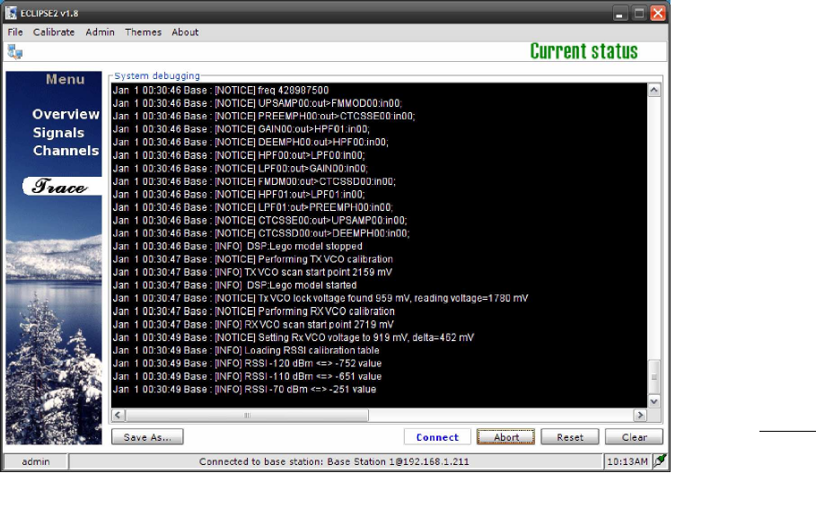
7.11. Trace
The Trace menu displays low-level internal software messages from the Reciter Module.
These messages can be saved to a log file and used for diagnostic purposes.
Figure 15 Trace Panel

ECLIPSE2 IPCommander User Manual
39
ECLIPSE2 IPCommander User Manual
40
8. Calibration
The Calibration Menu allows the audio codec, RF Exciter Power and Receiver RSSI values
to be saved to the Reciter Module.
Use the procedures in the Eclispe2 Technical Manual to calibrate the Reciter Module.
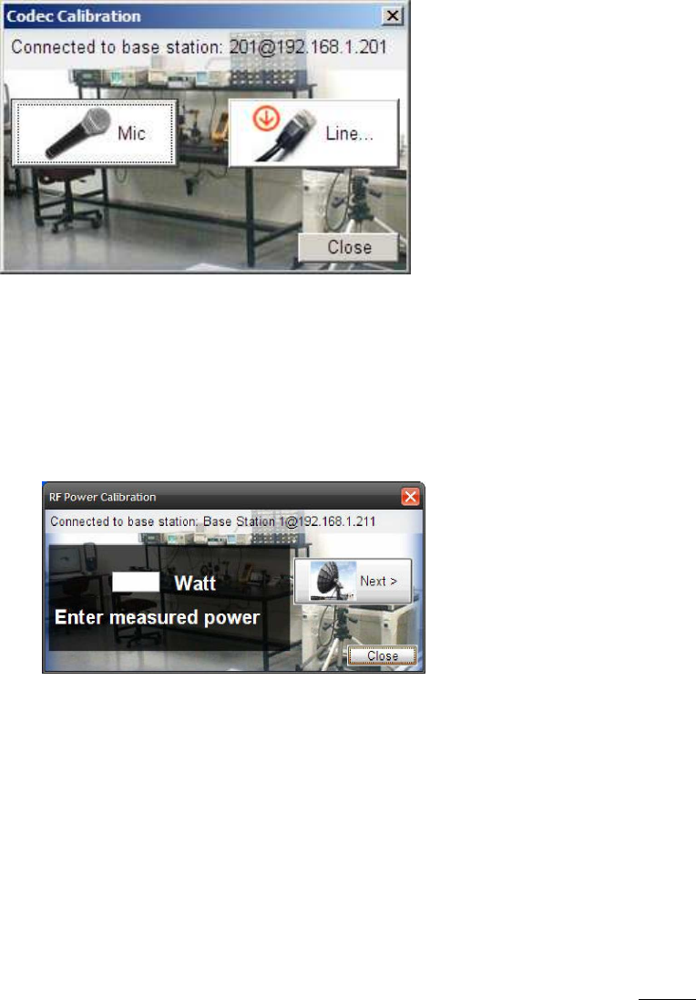
8.1. Codec calibration
The Codec calibration stores a reference audio level for the Line In and Front Panel
Microphone audio inputs.
8.2. Output power calibration
The Output Power calibration stores the user entered values measured from a Radio Test
Set. It sets the relationship between the actual power level in the Eclipse 2 and the value,
in units of watts, displayed by IP Commander.
Figure
16
Codec Calibration
Figure
17
RF Power Calibration

ECLIPSE2 IPCommander User Manual
41
8.3. RSSI calibration
Stores the signal strength value, in dBm, of the receiver module.
Calibrates the RSSI value displayed in IP Commander.
Refer to the Eclipse2 Technical Manual for the calibration procedure.
Figure 18 RSSI Calibration
ECLIPSE2 IPCommander User Manual
42
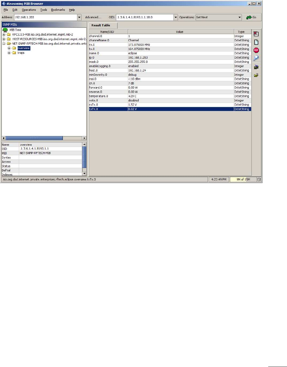
9. SNMP
Eclipse2 supports SNMPv2 protocol for major base station parameters.
SNMP database is available on request.
Figure 19 SNMP browser