RF Technology T500B Base station transmitter User Manual Manual T500
RF Technology Pty Ltd Base station transmitter Manual T500
UserManual.wiki
>
RF Technology
>
T500B User Manual
User manual with circuit diagrams removed
Navigation menu
Upload a User Manual
Namespaces
Wiki Guide
HTML
PDF
Info
Views
User Manual
Discussion / Help
Navigation
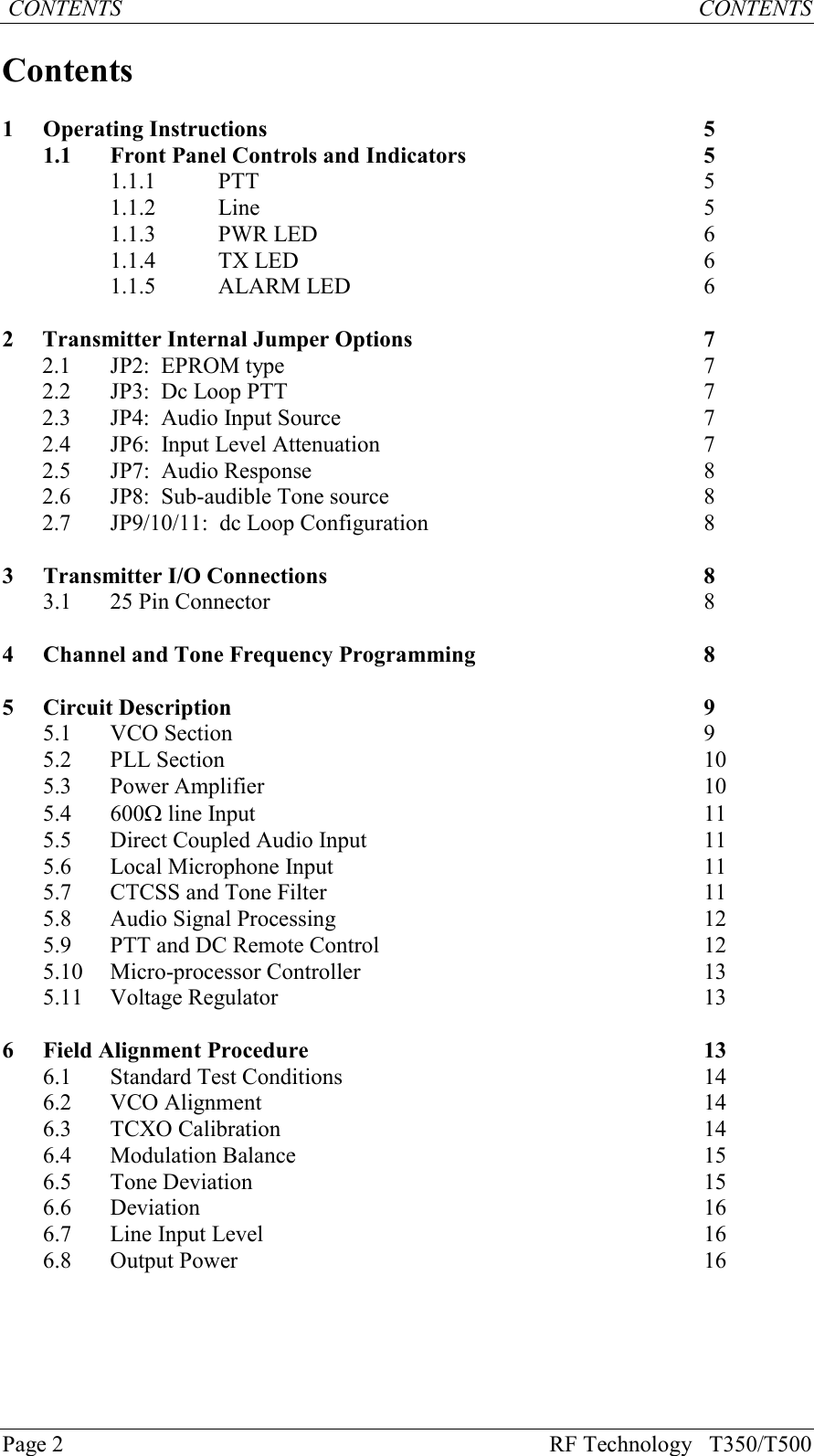
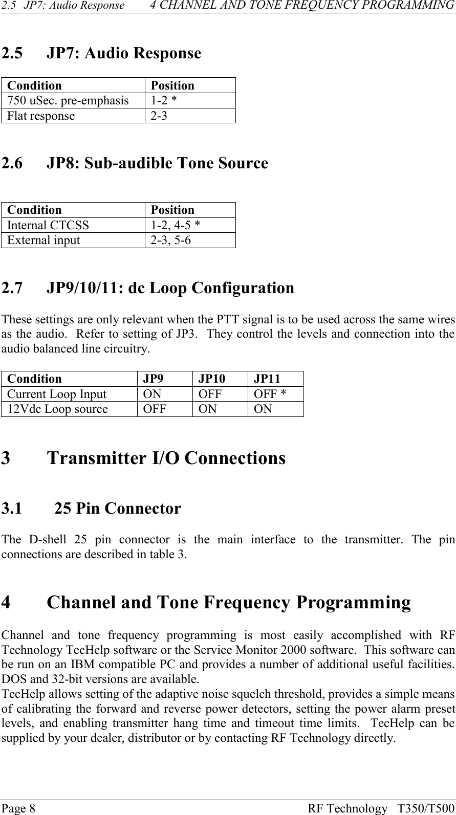
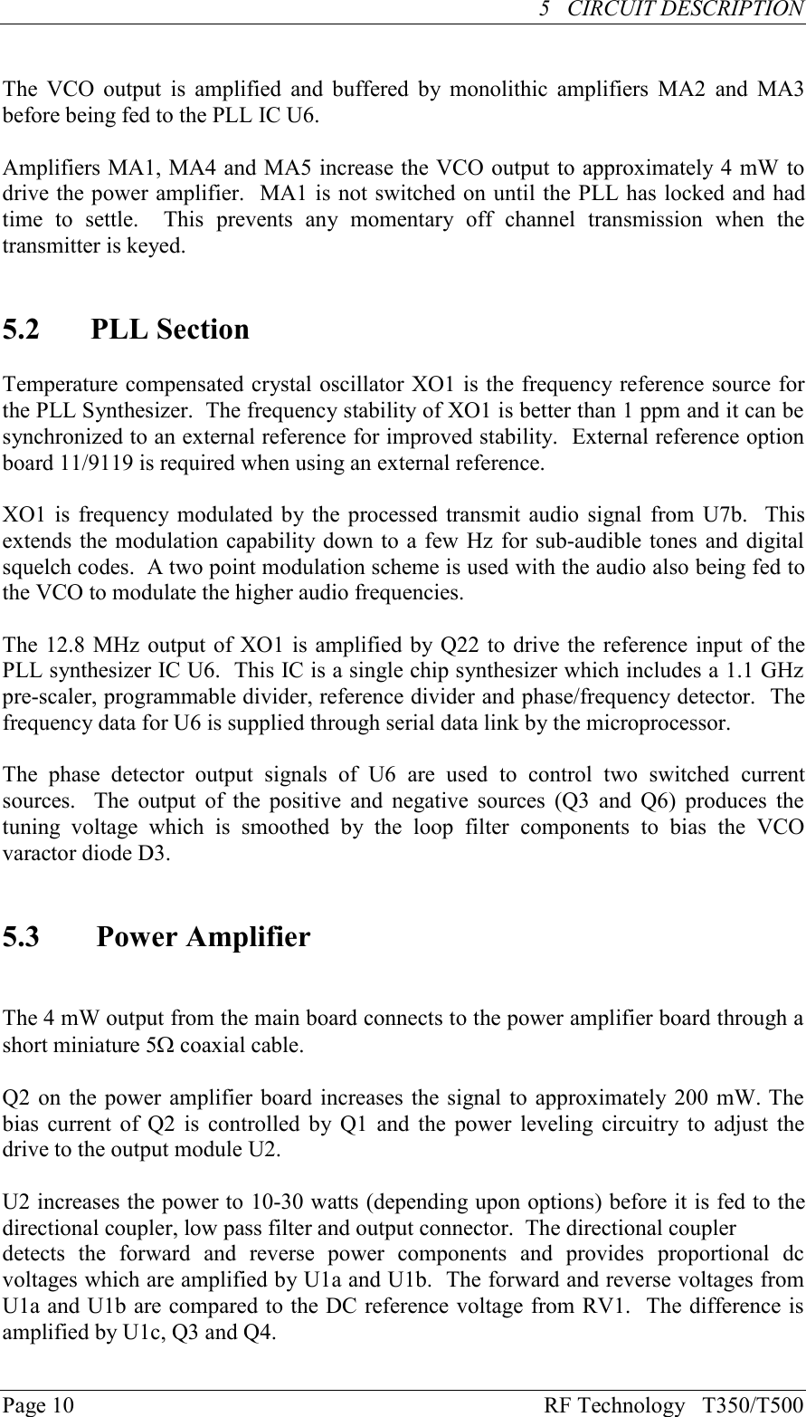
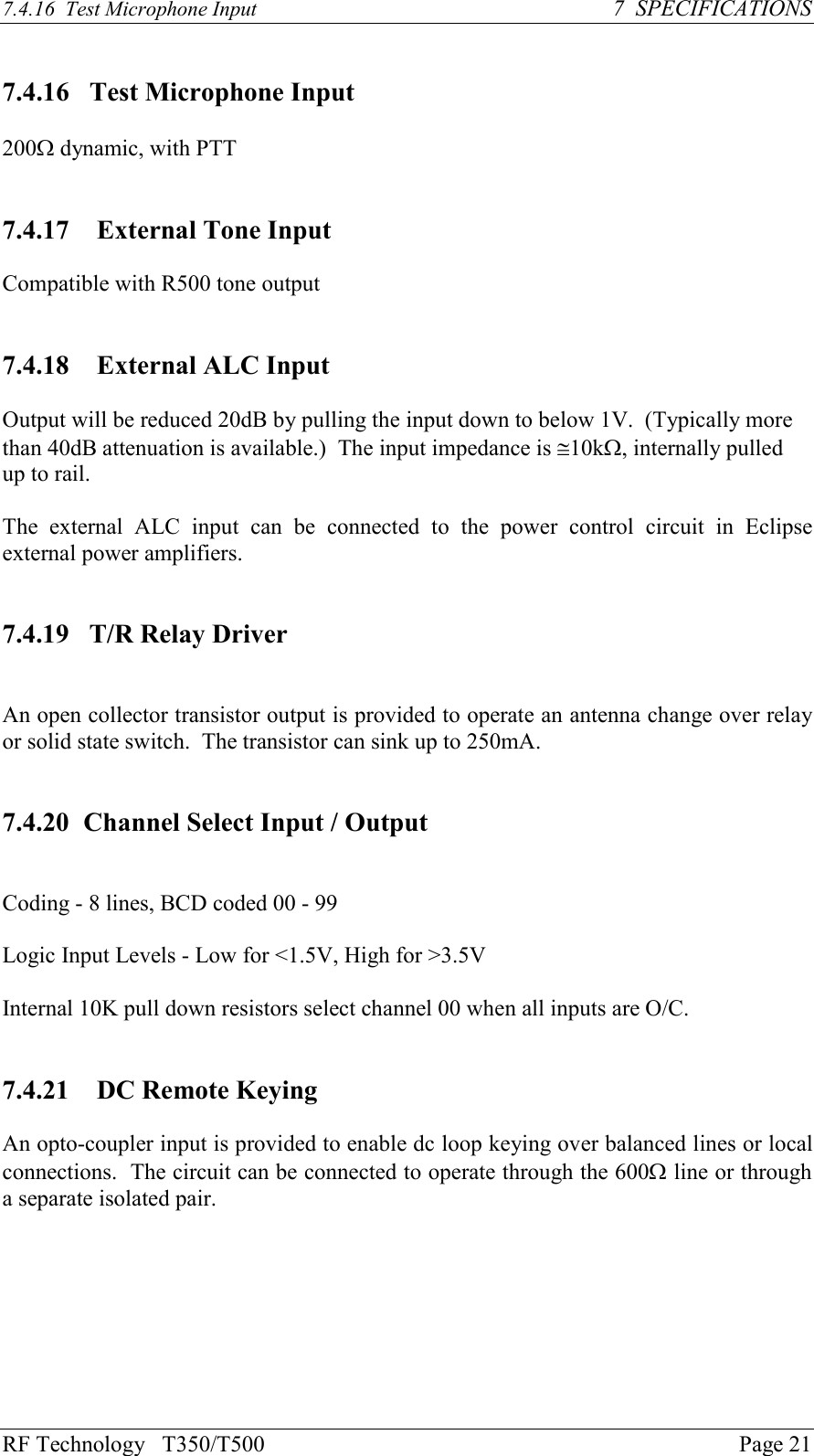
![RF Technology T350/T500Page 94 CHANNEL AND TONE FREQUENCY PROGRAMMINGFunction Signal Pins SpecificationDC power +12 Vdc 0 Vdc1, 1413, 25+11.4 to 16 Vdc GroundChannel Select 124810204080219221023112412BCD Coded0 = Open Circuitor 0 Vdc1 = +5 to +16 VdcRS232 Data InOut152Test and Programming use9600, 8 data 2 stop bits600W Line HighLow206Transformer IsolatedBalanced 0dBm Output150W / Hybrid 719Direct PTT input 3Ground to key PTTT/R Relay driver output 16 Open collector,250mA/30VSub-Audible Tone Input [+] 5>10kW, AC coupled[-] 18 (1-250Hz)High-Z Audio Input [+] 4>10kW, AC coupled[-] 17 (10Hz-3kHz)External ALC input 8 <0.5V/1mA to obtain>30dB attenuation, O/Cfor maximum powerTable 3: Pin connections and explanations for the main 25-pin, D connector.5Circuit DescriptionThe following descriptions should be read as an aid to understanding the block andschematic diagrams given in the appendix of this manual.5.1 VCO SectionThe Voltage Controlled Oscillator uses a junction FET which oscillates at the requiredtransmitter output frequency. A varactor diode is used by the PLL circuit to keep theoscillator on the desired frequency. Transistor Q20 is used as an active filter to reducethe noise on the oscillator supply voltage. The VCO is keyed ON by themicrocontroller through Q10. It is keyed ON when any of the PTT inputs are active andOFF at all other times.](https://usermanual.wiki/RF-Technology/T500B/User-Guide-327852-Page-9.png)