Contents
- 1. User Manual
- 2. Users Manual
Users Manual
HKRUR-3083
FRID long distance electronic tag reader
Instruction Catalog
Catalogue
1. Brief instruction of HKRUR-3083 Reader .............................................................3
1.1 The use of HKRUR-3083 Reader...............................................................3
1.2 The main function of HKRUR-3083 Reader..............................................3
1.3. Technology parameter of the HKRUR-3083.............................................4
2.The confifuration and interface instruction of HKRUR-3083 Reader ....................4
2.1 Every part of reader instruction ..................................................................4
2.2 Port explain.................................................................................................5
2.3.Tag operation ..............................................................................................6
2.4.Reader Work mode......................................................................................6
2.5.Interfacing identification: ...........................................................................7
3.The fitting of HKRUR-3083 reader.........................................................................7
4. Fitting modes of the reader ...................................................................................10
4.1 Reader Fitting modes................................................................................10
4.2 the fixation and height adjustment of the reader.......................................11
5. The demo program instruction pf HKRUR-3083.................................................12
Federal Communications Commission (FCC) Statement
You are cautioned that changes or modifications not expressly approved by the part responsible for compliance
could void the user's authority to operate the equipment .
FCC- Class B
This equipment has been tested and found to comply with the limits for a Class B digital device, pursuant to part 15
of the FCC Rules. These limits are designed to provide reasonable protection against harmful interference in a communications.
However, there is no guarantee that interference will not occur in particular installation. If this equipment does cause harmful
interference to radio or television reception, which can be determined by turning the equipment off and on, the user is
encouraged to try to correct the interference by one or more of the following measures:
- Reorient or relocate the receiving antenna.
- Increase the separation between the equipment and receiver.
- Connect the equipment into an outlet on a circuit different from that to which the receiver is connected.
- Consult the dealer or an experienced radio/TV technician for help.
RF Exposure Statement
To maintain compliance with FCC's RF exposre guidlines, this equipment should be installed and operated with minimum
distance 20cm between the radiator and your body: Use only the supplied antenna
1. Brief instruction of HKRUR-3083 Reader
The products can be compatible with multi-protocol, small volume, quickly read and multi-tag
identification.,the round- polar antenna is no limit of direction for tag, water proof, Meanwhile, it
can be used widely in RFID systems, the mainly applying sites are
² Logistics and warehouse Management::goods flow, warehouse management, and the flowing
management of mail, parcel, and luggage.
² Intelligent parking Management :Parking management and automatic charge
² Productive lines Management:Production process fixed identication
² Product counterfeit-proof inspection: Using memorizer’s write-protect functions inside tags
to identify true-false of products
² Other fields: widely used in club management,library,student’school,consumption
management,time management,dinner management and pool management
1.1 The use of HKRUR-3083 Reader
It can be used for goods identification and data collection,,specially used widely in the following
areas with its speciiality.
² Transportation management: road and ,railway transportation management and container
transportation management and so on .
² Motor vehicles management: use it to police station and transport department supervise and
manage the motor vehicles
² Road and bridge charge: as the product is able to read the tag data quickly in long
distance, ,road rate and bridge can be charged without stopping. Vehicles.
² Customs management: the management for goods to pass and transit the customs and
vehicles.
² Logistics and warehouse Management:Goods flow,warehouse management,and the flowing
management of mail,parcel,luggage.
² Parking management:in order to make management and charge autoautomatic
² Doors control management:including vehicles and people to pass in and out management.
² Craftworkm anufacture flow::supervise parts in the whole manafacture flow.
1.2 The main function of HKRUR-3083 Reader
1) Awaken the tag. :only the tags that be awakend can communicate with the reader and
prevent the disturb of those tags out of the system thereby confirm the credibility and nicety of
the exchange information between the reader and the tag of the system.
2) Read the tag data:not only can it read the ID NO.of the tag,but also the data of the appointed
tag storage area; not only can it read the single tag data,but also multi-tag data of the antenna wave
synchronously.
3) Real-in tag data:it can read-in data to the appointed tag storage area.
4) It can connect with the control equipment with standard W26 or W34 interface without
exploitation,, therefore convenient for use..
5) Connect the controller of PC machine through the communication interface to process the
data communication and exchange, and to provide SDK exploitation bag,, so as to make
customers exploit for use again.
1.3. technology parameter of the HKRUR-3083
1)Operation frequency: China standard(920~925MHz),FCCstandard903~927MHz)or order other
frequency band to work in jumping frequency appointed frequency..
2)Card-reading distance: identify distance and adjust range:1~6 meters.
3)Card-reading sense.twin pole mode technology
4)Card-reading time:single tag 64ID no.<6ms
5)Operation voltage:DC+9V
6)Operation temperature: -20℃ ~ +80℃;
7)Storage temperature: -40℃ ~ +85℃
2.The confifuration and interface instruction of HKRUR-3083
Reader
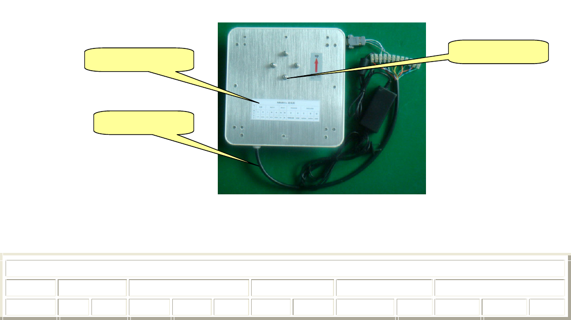
2.1 Every part of reader instruction
2 configuration instruction pf HKRUR-3083
The hookup of HKRUR-3083
Interface Power RS232 RS485 TRIGGER WIEGAND
Colour red black whihte purple gray brown yellow orange green blue pink green
Stationary barrier
Derivation line
derivation
Define +9V GNE TX RX GND A+ B- TRIGGER GND DATA0 DATA1 GND
2.2 Port explain
2.2.1 RS232
The reader provide RS232 communication interface for cooncting communication with control
nainframe((commonly the PC machine),the data format of the RS232 interface is 8 data bits, a
star bit and a stop bit, without parity bit; 9600,19200,38400,57600 and 115200 are the choices
for data modulus..RS232 communication interface support the fitting parameter ,demonstration
program, all the second exploitation bag function of the single communication of the reader.
2.2.2 RS485
MR series provide RS485 communication interface,, which can connect with interface of the PC
machine, in the condition of using RS232,RS485 changer for changing,,RS485 interface supports
all functions that KS232 supports,besides,KS485 a interface for tag data output, when using
theRS485 to upload tag data,,it can choose three kins of modes for transmission.
Initiative uploading: Upload data immediately when reader reads the tag.
Passivity uploading: It doesn’t upload data when treader reads the tag,but wait until the
mainframe to fetch data.
Reaponsion transmission:After reader reads aon tag, it will upload data repeatedlyuntil receives
the response velemen from the mainframe t
How RS485 uploads data format is like the following tables:
frame
head
address address entenna Tag data frame stern checkout
0x02 High
byte
Low byte One
byte
octor(ASCII) 0x03 One byte
Thereinto,the method of checkout is for the difference checkoutt of all the frontal bytes
The mainframe to get the orderframe format of data is like the following table showing:
Rame head Identification module address Order No. framestern
0x09 0x5B One byte One byte 0x83 0x0D
The mainframe to get the response frame is like the following table showing:
frame identification module address Oreer NO. frame stern
0x09 0x5B One byte One byte 0x82 0x0D
2.2.3 Wiegand interface
Reader supply one Wiegand data interface,users can choose Wiegand26 or Wiegand34
communication agreement,the data format of these two kinds of agreement is like the following
table showing:
Table one Wiegand26 format
P0 The formal 12 digits The latter 12 digits P1
Thereinto,“P0” is the even of the formal 12 digits,“P1” is the odd of the latter 12 digits
P0 The formal 16 digits The latter 16 digits P1
Thereinto,“P0”is the even of the formal 16digits,“P1” is the odd of the latter 16 digits
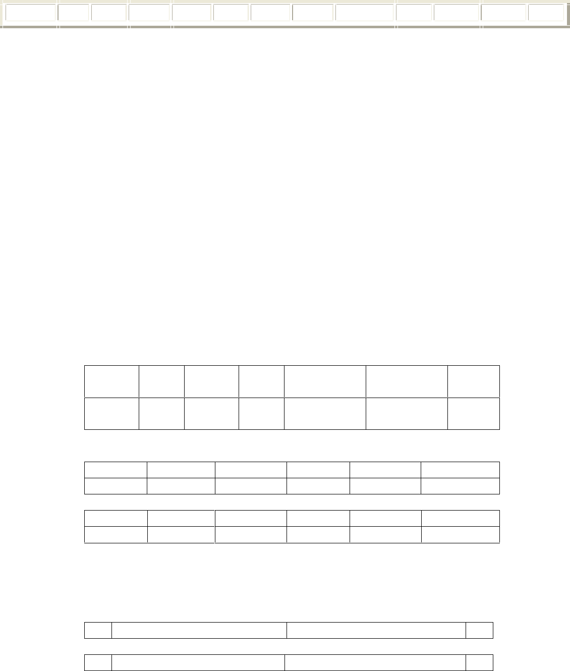
Wiegand interface is composed of 3 lines, the negative pulse of the first line indicates
“0”,anothere line indicates“1”,and the third one is “GND”. The typical format of every data
is like the following picture showing., Of course, users can settle the data formal of the Wiegand
interface according the special demand of the controller machine
In order to improve the of the reliability of data transmission ,the reader supply multi-transmission
function, namely when reading one tag,the Wiegand interface will be multi-transmission in
interval in some time. T he transmission tomes can be 1 to 3, The transmission interval can be
settled when display software.
2.3.Tag operation
2.3.1 ISO18000-6B tag
² Multi-tag identification:search all the tags in the rang of antenna radicalization and read their
octet UID
² Multi-tag reading:search all the tagsin the rang of antenna radicalization and read the octet
data from the beginning of the appointed address
² Single tag writing: write data of one tag at the appointed tag address
² Single tag locking: lockdown the data of the appointed tag address. After that , it won’t be
overwritted
² Inquire: about the Single tag locking :inquire about the locking state of the appointed
address.
2.3.2 EPC GEN2(ISO18000-6C)tag
² Multi-tag:identification: search all the tags in the rang of antenna radicalization and read
their EPC, the longest of EPC of EPCGENZ can reach 256 digits, now support 96 digits.
² Single tag initialization:define the EPC longness of the tag, popularly 96 digits.
² Single tag writing: read-in the EPC of the tag, one piece(16 digits)one time.
² Single tag locking: lock down the EPC of the tag after that, the EPC of the tag can’t be
overwritted.
² Single tag destroying:destroy tag, after that ,the tag can’t be used again
2.4.Reader Work mode
2.4.1 Command read: in this work mode, reader works under the control of PC or other
controller Reader can controller can communicate through RS232,RS485or one of the big net
interfaces This kind of working support all the function that the second exploitation bag supplies.
2.4.2 timing read : reader reads card in some cycle(can be settled),the data be read can be output
through appointed communication interface. This mode is only for reading to the tag operation.
2.4.3overwrite working((TRIGGER READ when the touching off port inputs low
voltage, ,reader begins to read card in cycle ,and shut off in a period of time.
2.5.Interfacing identification:
Interfacing identification is designed for reducing the prolixity of the data that reader uploads. If
choosing the function ,reader will only upload a set of data when reader reads the same card in
multi-connection. Namely that if the interval time of interfacing reading two time exceeds the
effective time,reader won’t process interfacing identification. So users should choose it according
special demand..
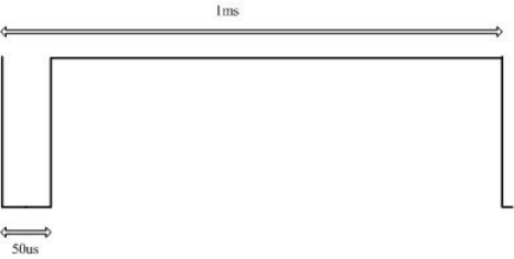
3.The fitting of HKRUR-3083 reader
Our company provide Config exe programs for the fitting of the working parameter of the
reader ,the parameter fitting program is like the following picture
5 fitting software interface
3.1 COM setting
Interface setting includes interface choice, band rate setting and address choice of reader. The
address of reader is from 1to 240.Only choosing the right address, can reader establishes
communication. Besides,, you can choose ¡°defaut¡±, which is fit for all reader, after clicking
¡°Connect¡±button ,PC and reader establish communication connecting.
After software and reader connecting, ,it reads the present working parameter of reader at once
automatically .Interface after connecting is like the following picture indicated:
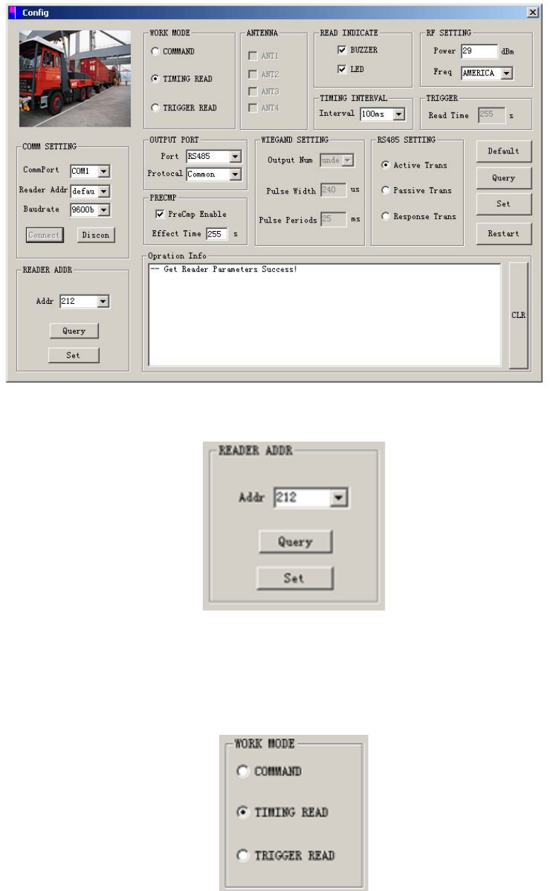
6 setting interface
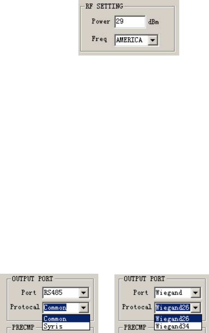
Reader address rejigger:
7 setting interface
If you want to amend the address of the reader, you can choose the new address under the frame of
the amending address column of the reader ,then click the ¡°set¡± button. The new address will bu
effective when reader reposition
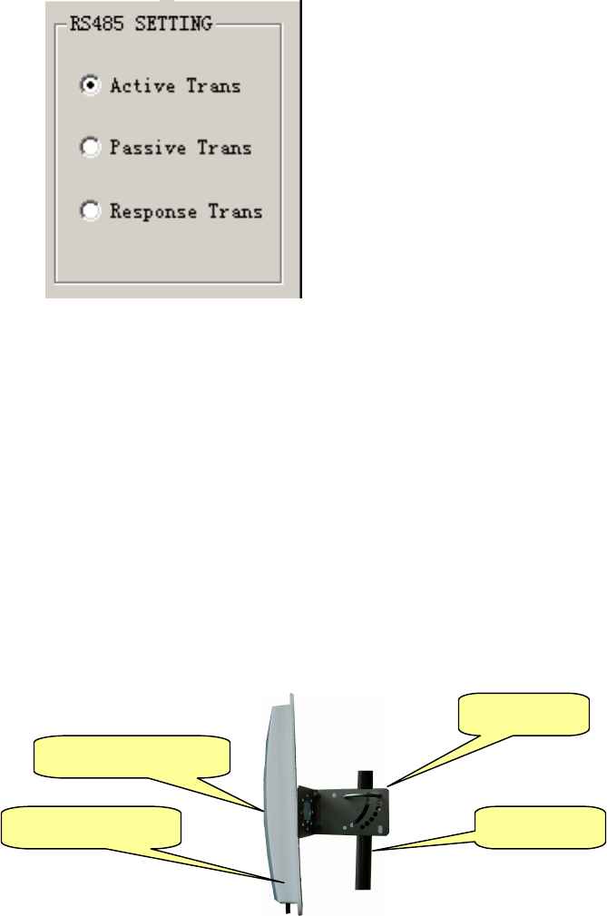
work mode choice:
setting interface
Users can configure the work mode of the reader through single choosing frame.. when choosing
the command ,reader can set radio frequency parameter and antenna (multicenter maching style )
at the same time, and other part become gray.. when choosing timing or touching off mode
Reader can set the parameter of radio frequency timer and communication interface. If choosing
touching off mode, ,it can set the parameter of the trigger. We will describe them one by on as
the following.
setting interface
Users can set the power and frequency of the radio frequency according application need. The
largest power parameter can be 30dBm.You can choose China standard(920MHZ~925MHZ) or
FCC(902MHZ~928MHZ)as the frequency of radio frequency, other frequency bands need
customize.
antenna setting
When using multicenter readers, you can choose antenna,, Choosing the corresponding antenna
in the check box means antenna invocation.
Read indicate:
Buzzer and LED are optinal, for reader to choose,users can choose them according to demand.
Timing interval:
this frame includes setting the frequency of reading tag(namely setting time for cycle reading)
and the interfacing identification. Setting time for cycle reading can be 10ms`1000ms.Users can
choose interfacing identification and set the effective time for interfacing identification .If no
need of setting effective time, fill in ¡°0¡±instead.
Communication out port parameter setting:
Setting data out of communication pork and other agreement .When choosing RS485
communication agreement, Syns agreement and common transmission agreement are optional.
The format of common transmission agreements are like the predescription.. Please make
reference to the Syns controller information about Syns agreement.
Wiegand setting:
When choosing Wiegand interface ,you can choose Wiegand26 or Wiegand34 agreement.
Picture 10 interface setting
RS485 setting:
Interface setting
This frame is used for setting the Wiegand interface parameter, ,Include Wiegand output times
and signal format. Wiegand signal format needs setting Wiegand pulse breath(means low impulse
breath)and code element cycle(means the time of a bit data)
After every function choosing, click¡±SET¡±button The successful setting parameter will be
effective when reader repositions. Suers can click¡±Restar¡±button to make reader reposition.
Fourth The fitting of HKRUR-3083 Readerf
4.Fitting modes of the reader
4.1 Reader Fitting modes
Skatch map of fitting effect
There are two kind of modes that HKRUR-3083 crutch fitting: ¡°frank fitting that like the figure 1¡±
and ¡°crutch fitting like the shape of letter L¡±.like the following picture indicatedThey can bo
choosen according to the application nedd and locale practice..generally,The reading distance of
frank fitting is nearer,but ffitted simply,while crutch fitting farrer but complex.
Set clamp
MR6021AReader
Fitting Reader data line
HKRUR-3083Reader HKRUR-3083 Reader
Frank fitting like the figure 1 crutch fitting like the letterL
The fitting modes of the reader
4.2 the fixation and height adjustment of the reader
When frank fitting ,it demands that the crutch dia.of the reader 50 to 60mm while length2.2m
Using stain steel material that more than 1.3m thick is the best choice. Fix the reader to the top of
the crutch with the self-provided fastening pin in the casing of HKRUR-3083 reader .Adjust the
height from the center of HKRUR-3083 reader to the level of carriage way, according to the
vehicle style(mainly indicates the oversize vehicle and landauter), generally about 2.0m(from
1.2m to 2.2m)
When crutch top fitting like the shape of letter L,it demands the dia. of L shape (or dragon-door
shape) crutch is from 60 to 80mm,while rail dia.60 to 60mm.It is best to sue stain steel material
that more than 12 to 20mm thick. Fix the HKRUR-3083 reader to the rail that near the middle
carriage drive. The height that the rail to the ground is needed to adjust from 3.5m to
4.0m,according to the height of vehicle
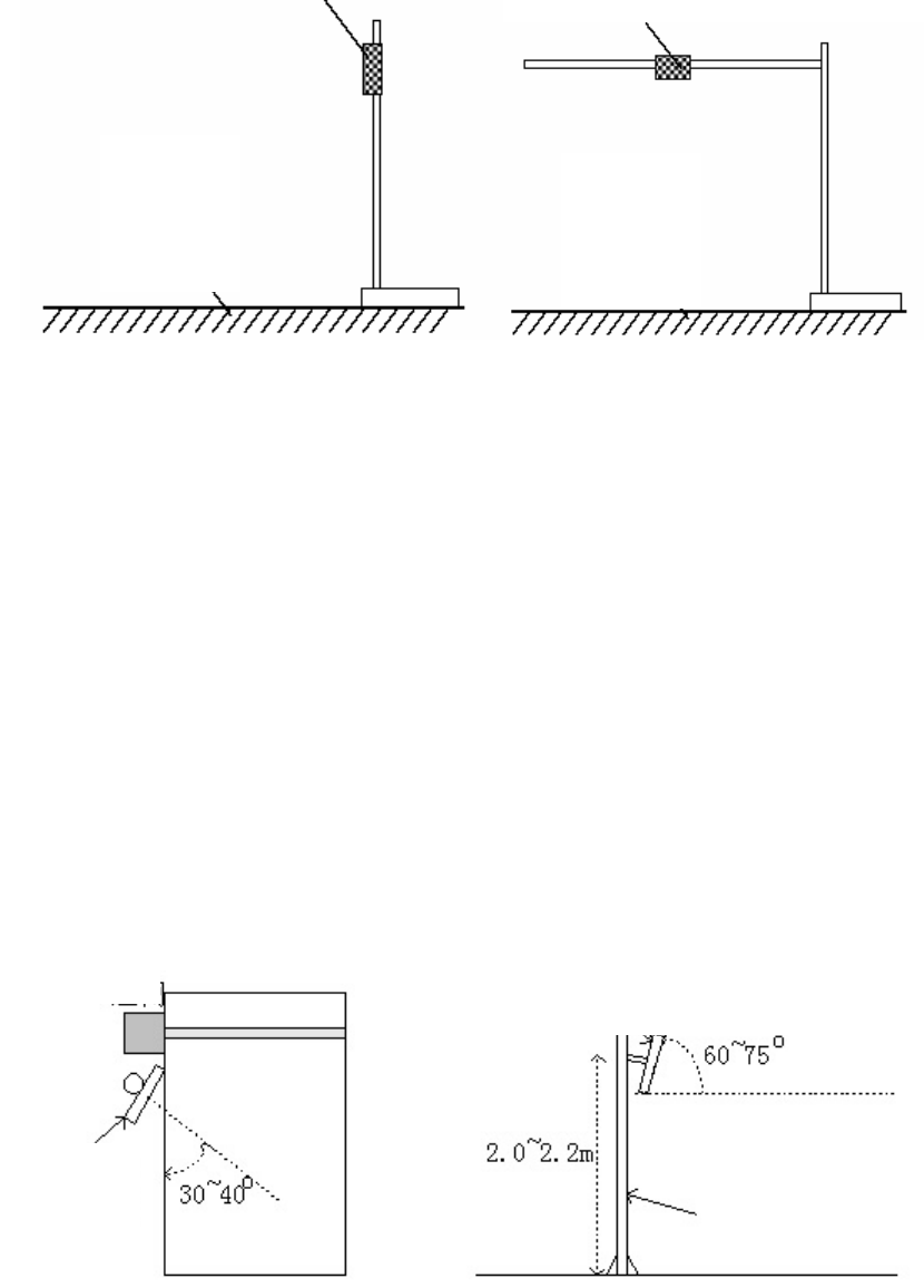
the azimuth adjustment of the reader
The sketch map of the azimuth angle adjustment of HKRUR-3083reader
Antenna angular:indicates the included angle between the antenna and level when the antenna
inclines to the ground.
azimuth angle of antenna:indicates the deviation angle when antenna deflects to the direction of
MR6021A
reader
MR6021A
railing
Pillar
carriage drive.
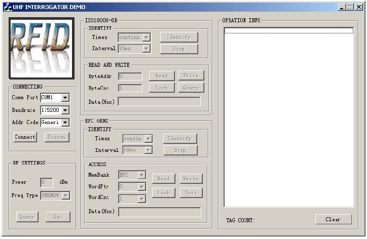
5. The demo program instruction pf HKRUR-3083
The demo program of the reader provides the contend of all kinds of operation to the tag and
parameter setting of radio frequency Users can evaluate the function of the function of the reader
through this demo program, of consider to make the second exploitation of the reader.
The demo program of the reader includes ¡±DEMO exe¡± and ¡°MR915ApiV10.dll¡±Please put this
two parts in the same file catalog ,then double click ,it will begin to circulate ,the interface is like
the following picture indicated.
Demo software interface
Choose the COM communication port and baud rate you use, and choose the right reader address.
Click ¡±Connect¡± to establish connection with the reader .After successful connection, the right and
left information frames will indicate the successful connection and the edition NO. of the reader
firmware. And you can operate all demos
Sixth :the second exploitation of HKRUR-3083
Users can make the second exploitation to the application software reader according to the
need. .We provide the exploitation bag basis on the C language ,which supports the environment
of VC++,vb, Dephi and C+Buider and so on .Please make reference to the <<NRreader SDK
instruction>>about the use of exploitation tag.

NOTES:
1. Frequency Range: 903MHz-927MHz.
2. The transmission and receiver is the same for the 20dB bandwidth.
3. The transmission of each channel of the transmitter is to send sync code. The receiver will
recognize the sync code, confirm the channel and analyze the data.
4. Each frequency is used equally on the average by each transmitter.
5. The transmission channel is based on the Hop data as below:
Channel to Frequency Table (MHz)
0 1 2 3 4 5 6 7 8 9
903.00 903.48 903.96 904.44 904.92 905.40 905.88 906.36 906.84 907.32
10 11 12 13 14 15 16 17 18 19
907.80 908.28 908.76 909.24 909.72 910.20 910.68 911.16 911.64 912.12
20 21 22 23 24 25 26 27 28 29
912.60 913.08 913.56 914.04 914.52 915.00 915.48 915.96 916.44 916.92
30 31 32 33 34 35 36 37 38 39
917.40 917.88 918.36 918.84 919.32 919.80 920.28 920.76 921.04 921.72
40 41 42 43 44 45 46 47 48 49
922.20 922.68 923.16 923.64 924.12 924.60 925.08 925.56 926.04 926.52
50
927.00