RFNet Technologies 000002 802.11 b/g Wireless Router User Manual INTRODUCTION
RFNet Technologies Pte Ltd 802.11 b/g Wireless Router INTRODUCTION
APRT 2001g User Manual

User Manual
Router
with
802.11g 54 Mbps, 108Mbps Wireless LAN
and
4-port Switch

FCC Compliance
NOTE: This equipment has been tested and found to comply with the limits for a Class B digital
device, pursuant to Part 15 of the FCC Rules. These limits are designed to provide reasonable
protection against harmful interference in a residential installation. This equipment generates,
uses and can radiate radio frequency energy and, if not installed and used in accordance with the
instructions, may cause harmful interference to radio communications. However, there is no
guarantee that interference will not occur in a particular installation. If this equipment does cause
harmful interference to radio or television reception, which can be determined by turning the
equipment off and on, the user is encouraged to try to correct the interference by one or more of
the following measures:
-- Reorient or relocate the receiving antenna.
-- Increase the separation between the equipment and receiver.
-- Connect the equipment into an outlet on a circuit different from that to which the receiver is
connected.
-- Consult the dealer or an experienced radio/TV technician for help.
Any changes or modifications not expressly approved by the party responsible for compliance
could void the user’s authority to operate the equipment.
No special accessory is required to enable the equipment to comply with the emission limits.
In order to comply with FCC RF Exposure requirements, the APRT-2001g(802.11g Wireless
Broadband Router) must be installed and operated in such a way so as to maintain a minimum 20
cm separation distance between the antenna and all persons, during normal operations.

Contents
INTRODUCTION............................................................................................................. 1
THE PRODUCT.................................................................................................................. 1
PRODUCT FEATURES ........................................................................................................ 1
BASIC IP NETWORKING ................................................................................................... 2
WIRELESS LAN ............................................................................................................... 3
GETTING STARTED ...................................................................................................... 5
BOX CONTENTS ............................................................................................................... 5
CONNECTING THE ROUTER .............................................................................................. 5
QUICK START CONFIGURATION (FOR DSL MODEMS) ..................................................... 7
WEB CONFIGURATION ............................................................................................... 8
QUICK CONFIGURATION................................................................................................... 9
STATUS .......................................................................................................................... 10
STATISTICS .................................................................................................................... 11
LAN & DHCP CONFIGURATION ................................................................................... 12
WAN CONFIGURATION ................................................................................................. 14
PPP CONFIGURATION .................................................................................................... 14
BRIDGE .......................................................................................................................... 16
WIRELESS ...................................................................................................................... 18
NAT .............................................................................................................................. 22
DMZ CONFIGURATION .................................................................................................. 23
SNTP CONFIGURATION ................................................................................................. 24
PORT FORWARDING ....................................................................................................... 25
FILTER ........................................................................................................................... 27
WEB SECURITY CONFIGURATION................................................................................... 29
ADMIN USERNAME AND PASSWORD .............................................................................. 30
FIRMWARE UPDATE ....................................................................................................... 31
SAVE CONFIGURATION .................................................................................................. 34
PC CONFIGURATION ................................................................................................. 35
DHCP IP ADDRESS ....................................................................................................... 35
FACTORY RESET......................................................................................................... 37

INTRODUCTION
The Product
The product is based on the IEEE 802.11g standard, which is the latest 54Mbps Wireless LAN
(WLAN) standard. This standard is five times faster than the widely deployed WiFi (802.11b)
products that are found in homes, airport and public wireless hotspots. Because 802.11g uses the
same 2.4GHz frequency band, the product is fully interoperable with existing WiFi cards and
devices.
Having two wireless protocols in one product ensure that your investments are protected, while
enabling you to enjoy the fastest Wireless LAN speed.
The product is a combination of 3 devices:
a. Wireless LAN Access Point (AP) compliant to 802.11b and 802.11g standards.
b. 4-port Auto MDI/MDIX Switch
c. Router with NAT, DHCP Server built-in.
The product is an all-in-one device that allows multiple PCs to share a common broadband
(ADSL/Cable) modem. It can serve up to 4 Ethernet-PCs and many WLAN-notebooks. The built-
in NAT and DHCP Servers ensure almost plug-and-play convenience for your home network.
Advanced features such as Firewall, DMZ, WPA Encryption and 802.1x Authentication make this
a product equally suitable for your office needs.
Product Features
Fully compatibility with IEEE 802.11g WLAN standard
Wireless data rate of up to 54Mbps
2.4GHz license-free frequency band
Router shares the broadband modem among multiple PCs and laptops.
4 Auto MDI/MDIX 10/100 Ethernet ports, 1 WAN port
Full backward compatibility with 802.11b standard (WiFi 11Mbps)
802.1x Authentication. Used with a RADIUS server to check and verify the identity of
WLAN users.
WEP (Wired Equivalent Privacy). A simple WLAN encryption standard to protect wireless
data from sniffers.
WPA (WiFi Protected Access). An improved WLAN encryption standard where the secret
key changes automatically at regular intervals.
TKIP (Temporal Key Integrity Protocol). When used with a corporate RADIUS
server, the WLAN encryption key is changed regularly. Used for high security
enterprise networks.
Pre Shared Key. For the home user without a RADIUS server. A new key is
generated each time the PC connects.
Firewall protects your network from the Internet.
Built-in NAT and DHCP Servers greatly simplify the network setup.
Intuitive Web-based configuration
Access Control List provides added security
Page 1

Basic IP Networking
IP = Internet Protocol
IP stands for Internet Protocol. In an IP network, every device has a unique IP Address (For
example: 192.168.1.35) to identify itself. There are two ways of assigning an IP address to a PC
or Router: Static and Automatic (DHCP). Static IP addresses are keyed-in manually, while
Dynamic IPs are distributed by a DHCP Server.
Ports
Every packet of traffic is identified by its Source and Destination Addresses, which would ensure
that the packet arrives at the correct destination. A Port Number is also embedded in each
packet; to identify which software application that generated and uses that packet. Therefore, if
the Router blocks a certain port number, it denies the particular software from using the
connection.
Static IP Address
Static IP addressing ensures that the device will always have the same IP address. Static
addressing is commonly used for your servers.
Dynamic IP Address
A dynamic IP address is one that is automatically assigned to a PC. These IP addresses are
“dynamic” because they are only temporarily leased to the PC when it connects to the network.
This is the most convenient and common way of managing IP addresses in a network. The
Server that manages this pool of IP addresses is called the DHCP Server. The product has a
DHCP Server built-in to simplify the network management.
DHCP (Dynamic Host Configuration Protocol)
The PC obtaining an IP address from the Server is called the DHCP Client. If there is already a
DHCP Server running on your network, you must disable one of the two DHCP servers. Running
more than one DHCP server together will cause network problems!
What is a Router?
A router is a network device that connects two networks together, to let them communicate. All
the PCs in your home or office would be considered to be in one network: the Local Area Network
(LAN). The Internet (including the ADSL modem) is considered to be another network: the Wide
Area Network (WAN). The Router serves 2 purposes:
Connect all the PCs in the LAN together, allowing them to communicate with one
another. (File sharing, Printer sharing etc.)
Connect all the PCs in the LAN to the Internet, allowing them to simultaneously surf the
web and access e-mails.
The Router is connected to 2 networks at the same time. Therefore, it has two IP addresses: one
for the LAN, and one for the WAN. The Router’s LAN IP address can be configured, but it is best
to use the default settings. The WAN port is a DHCP client by default.
Page 2

Wireless LAN
A Wireless LAN (WLAN) is a computer network that transmits and receives data with radio
signals instead of using cables. WLANs have become common in homes, offices, airports and
public Hotspots. WLAN can support the same applications and software that run on a wired
network (LAN). Besides supporting the same software and functions, WLAN brings greater
convenience and eliminates the need to lay Ethernet cables in a home or office.
The Router is based on the finalised 802.11g standard. The IEEE 802.11g standard is an
improvement on the 802.11b (WiFi) standard. It increases the data rate up to 54 Mbps within the
2.4GHz band. As the 802.11b standard is also using the 2.4GHz frequency band, the product is
fully backward compatible with the older 802.11b devices. WiFi cards can be used to connect to
the Router at 11Mbps.
The Router can even support 108Mbps WLAN if the user is using a recommended Turbo-capable
Cardbus.
The Router is also known as the Wireless Access Point (AP). The PC using the Cardbus is
known as the Client. WLAN networking involves a few additional parameters to be configured:
SSID
The SSID is the “network name” for the WLAN network. The SSID is any name, and can be any
set of characters or numbers, and must be configured on both the AP and Client. The Client sniffs
the radio frequencies for an AP with the same SSID with itself. The client locks onto the AP and
they are “associated”.
To enable plug-and-play convenience, most client cards can sniff the frequencies to extract the
available SSIDs to let the user choose from. Alternatively, setting the client’s SSID to “ANY” can
allow it to connect to most APs regardless of the AP’s SSID setting.
Encryption
WLAN traffic can be captured by anybody to be read! The solution is to use encryption to make
the traffic appear as random characters to the eavesdropper. Both the AP and client must use the
same encryption standard and key to enable them to decode the “rubbish”. If the encryption
settings are mismatched, the client and AP cannot associate. WEP (Wired Equivalent Privacy) is
the most common WLAN encryption standard.
MAC Address Control
Every client card has a unique MAC Address. This MAC Address can be input into the AP
(Router), such that the AP only allows this pool of MAC Addresses to use the WLAN.
Channel
There are a total of 13 channels in the 2.4GHz band. Depending on regulation, not all the
frequencies may be available in every country. Frequency is configured on the AP only. The client
searches for the AP and locks onto that AP’s channel.
Signal Strength
Radio signals drop in power over a distance. Even if all the settings are correct, a low signal
strength makes association impossible. The usable distance between the AP and client can
range from a few meters indoor to 200m outdoors maximum. When setting up the AP, make sure
that you:
Keep the distance from the AP to the clients as short as possible.
Page 3

Make sure that the WLAN signals do not have to pass through too many concrete walls
and metal structures to reach the client.
Make sure that APs are located far away from one another to avoid interference.
Interference
Interference happens when 2 APs with the same channels are placed near to one another. The
speed of the network drops and the signal strength fluctuates wildly.
Roaming
Association happens when the SSID, Encryption and MAC Address Control settings are correct
between the AP and client. If 2 APs with these same settings are located in the same area, the
client would choose to associate to the one which gives it a better signal strength. The client
would roam over to the 2nd AP when he moves nearer to it. The client switches AP and
frequency as he does so.
Page 4
GETTING STARTED
Box Contents
Kindly check the contents of the box:
802.11g Wireless Router
DC Adapter
Ethernet cable
CD Manual
Quick Start Guide
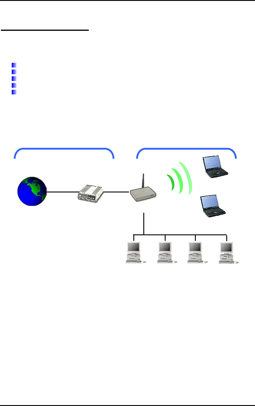
Connecting the Router
The router is connected to the WAN and LAN networks.
LAN
WAN
Router
Modem
Internet
Page 5
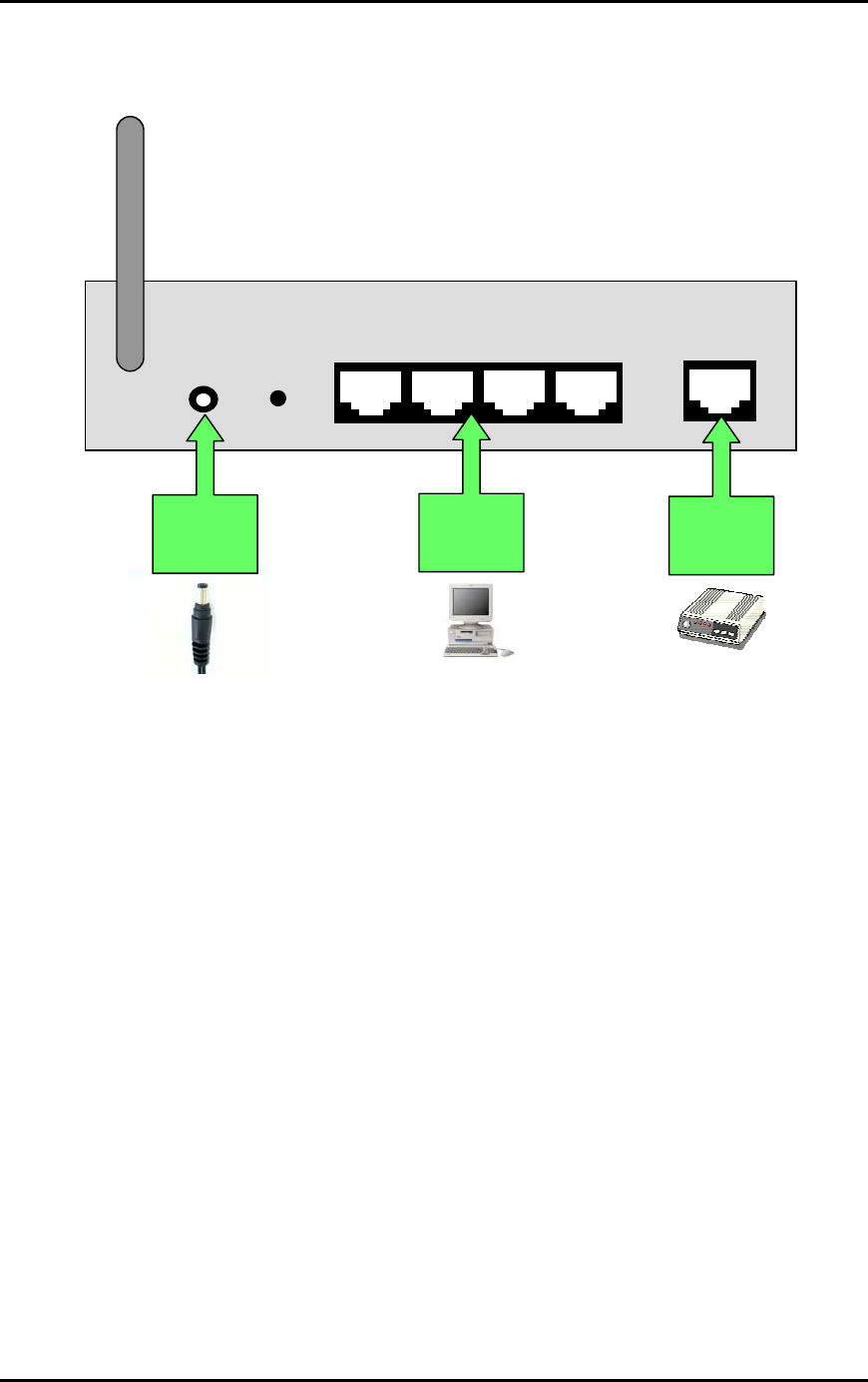
The cables are all connected to the back-panel of the Router. The PCs and Modem are
connected to the Router via Ethernet cables.
DC
Adapter Modem
PC
Antenna
LAN 1 - 4
DC Reset WAN/ DSL/
Cable
Back Panel of Router
Page 6
Quick Start Configuration (For DSL Modems)
This section is a quick-start guide applicable to most users. This assumes that the user is
connecting the WAN port to a ADSL modem.
1. Connect the network as shown previously.
Switch on the Modem BEFORE you switch on the Router. Every time.
Check that the WAN light on the Router lights up.
If your PC is connected via Ethernet cable, check that the
corresponding LAN LED lights up on the Router.
If your PC is wireless, check the PC’s card utility to make sure that the
signal strength is good.
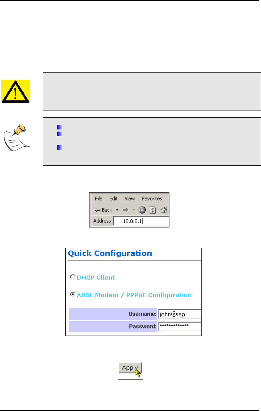
2. Open a Web browser (Internet Explorer, Netscape etc.)
3. Type the Router’s LAN IP (10.0.0.1) address into the browser’s Address field.
4. The Quick Configuration page opens up.
5. Enable ADSL Modem/PPPoE.
6. Key in the ADSL Username and Password provided by your ISP.
7. Press Apply.
8. Reboot the Router.
Page 7
WEB CONFIGURATION
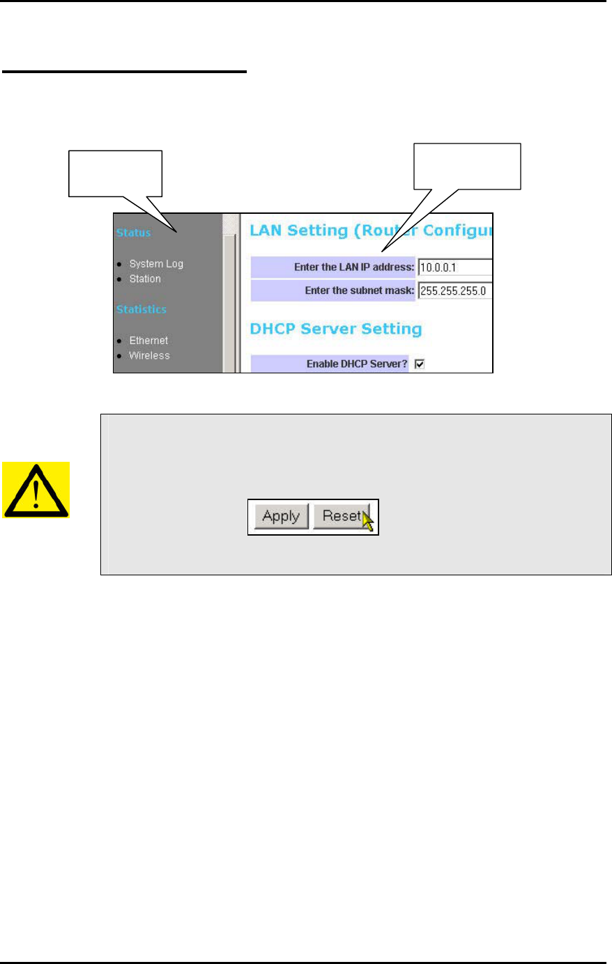
In every Router Web Configuration page, the left panel is the navigation menu containing the
main sections. The right-side frame is where the detailed configuration is done.
Configuration
panel
Navigation
panel
Remember that after every configuration change, it is necessary to:
- Click Apply on the page.
- Reboot the Router.
The changes take effect only AFTER Reboot.
Page 8
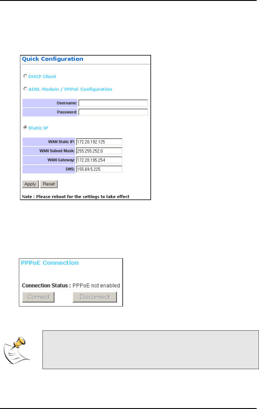
Quick Configuration
This page contains the most important settings to get the Router functioning in either a home/
small office environment. Basically, this page specifies what the WAN port is connected to.
DHCP Client: By default, or when you boot up the Router for the first time, the WAN port is in
DHCP Client mode. The WAN port will obtain an IP Address from an upstream DHCP Server or
Cable modem.
ADSL Modem / PPPoE: Select this option if the WAN is connected to an ADSL Modem. Key in
your ISP-provided Username and Password.
Static IP: This setting is for advanced users only. You assign a Static IP to the WAN port.
Connect/Disconnect: The buttons allow you to manually Connect/Disconnect the ADSL
connection. The status of the ADSL connection is also shown.
If ADSL Modem/PPPoE is selected, the Router automatically dials the
connection at every power up.
Page 9
Status
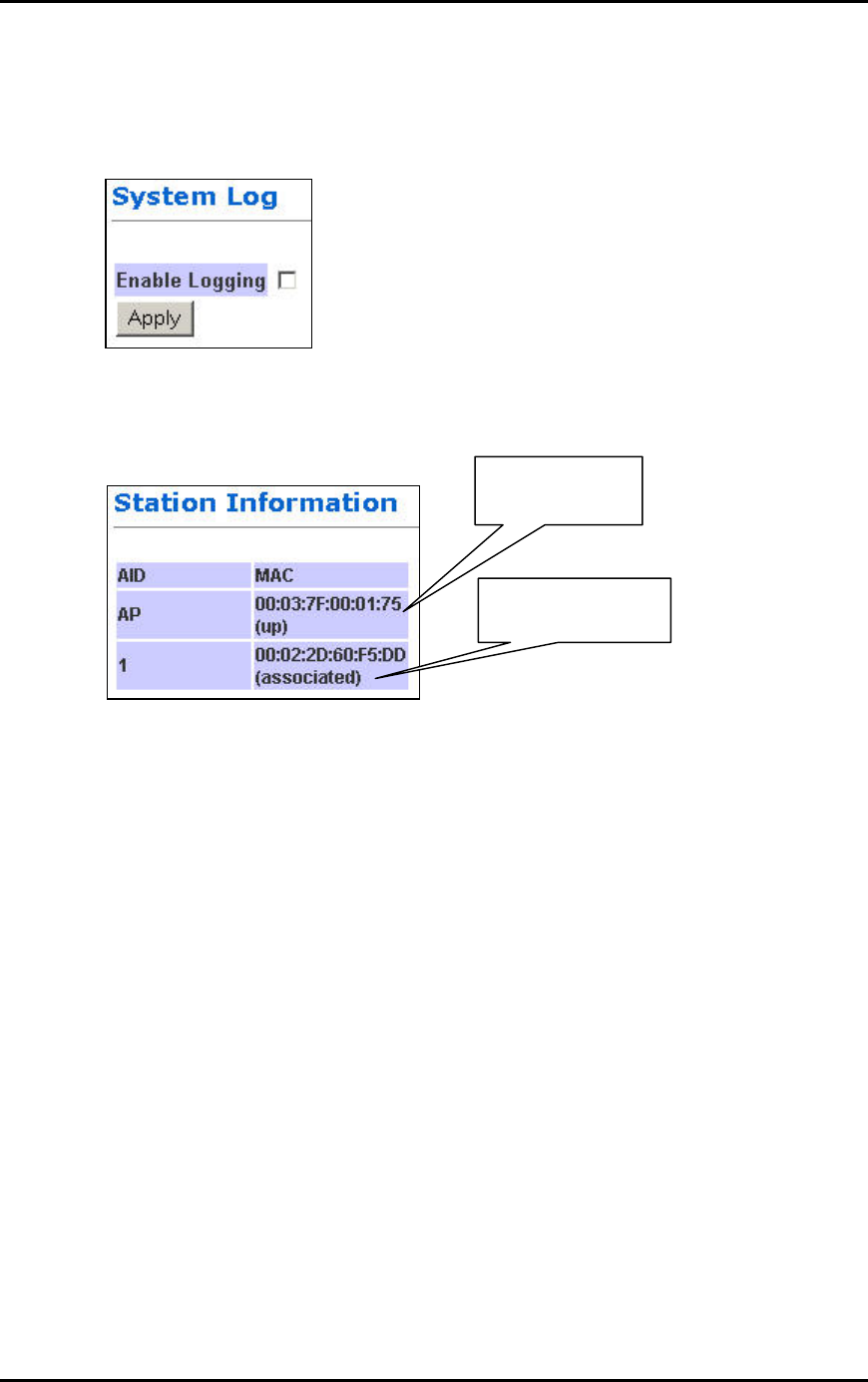
System Log
This page shows the system log of the Router. You can Enable/Disable the logging.
Station
MAC Address of a
active CardBus.
MAC Address
of your Router.
The Station page shows the status and MAC Addresses of the WLAN network.
Page 10
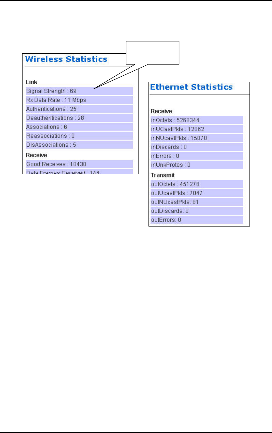
Statistics
Signal-to-Noise
Ratio.
Ethernet and Wireless Statistics show the statistics of the traffic handled by the Router. The
Signal Strength parameter shows the Signal-to-Noise ratio of the Wireless link. The higher the
number, the better the link.
Page 11
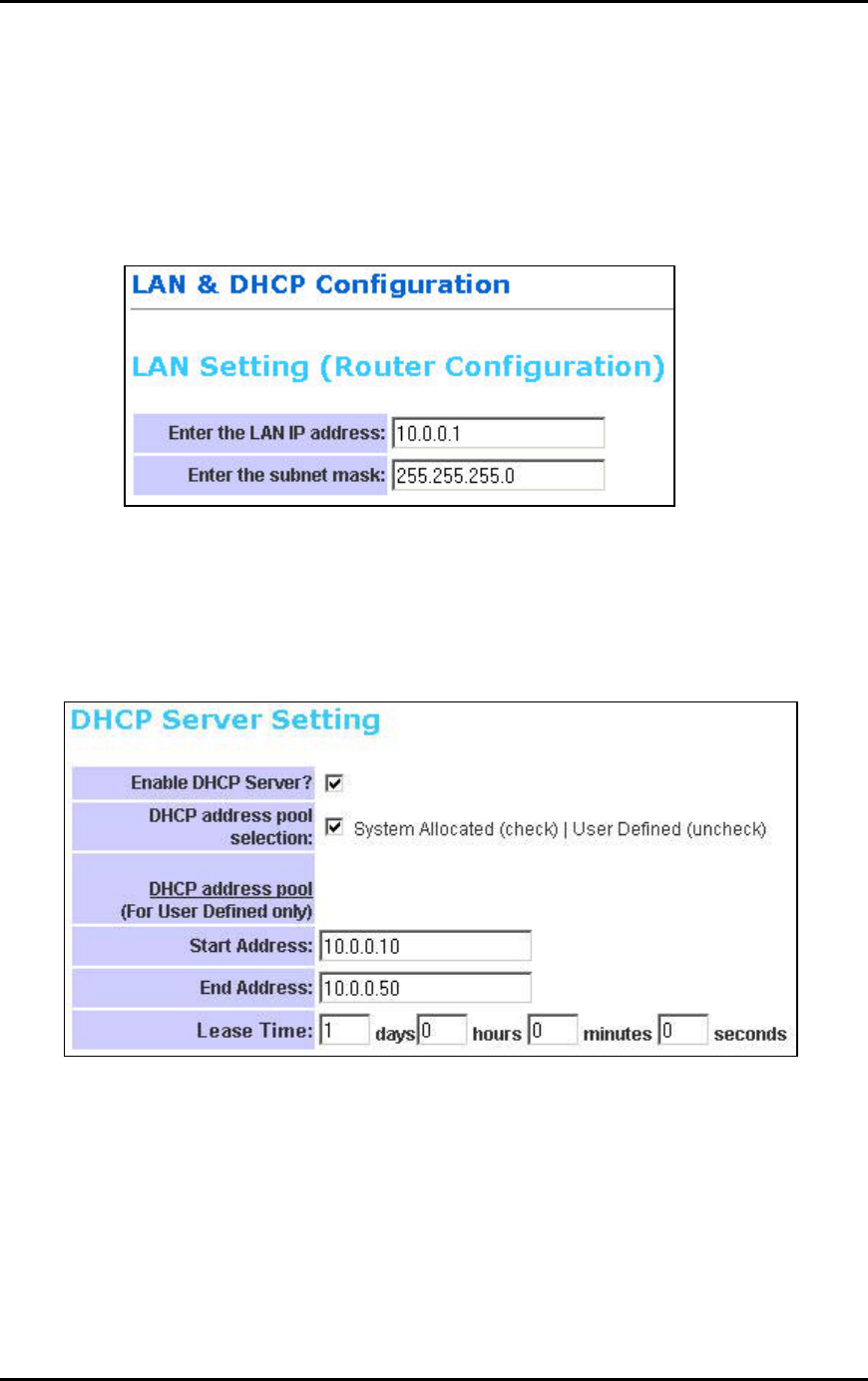
LAN & DHCP Configuration
This page is for the configuration of the Router’s internal (LAN) IP Address and the properties of
the built-in DHCP Server. Take note that the built-in DHCP Server distributes IP Addresses to
both the LAN ports and the WLAN clients.
LAN Setting
LAN IP address: This is where you assign a local IP address to your router’s LAN port. The
factory default value is 10.0.0.1. It is not recommended to change the LAN address for no reason.
Subnet Mask: This is where you assign the corresponding subnet mask. The default subnet
mask is 255.255.255.0.
(Note: When you change the LAN Setting of the Router, you need to reset/renew the Local computer IP address.)
DHCP Server Setting
Enable DHCP Setting: Tick to enable the built-in DHCP (Dynamic Host Configuration Protocol)
Server. When enabled, the Router will provide IP addresses to the computers connected to the
router.
DHCP address pool selection: If this is selected, router will assign IP address automatically
from the pre-defined pool. If de-selected, you would have to define the range of the pool
manually.
DHCP address pool (For User Defined only), Start Address: This is the start address of the
DHCP pool. The router will assign this to the first computer connected to the router.
(Note: This setting will only take effect when User defined is selected under DHCP address pool selection.)
DHCP address pool (For User Defined only), End Address: This is the end address that the
router will assign to the computers connected to the router.
Page 12

(Note: This setting will only take effect when User defined is selected under DHCP address pool selection.)
Lease Time: The amount of time a network computer will be allowed to connect with the DHCP
Server. By default, the lease time is 1 week.
(Note: This setting will only take effect when User defined is selected under DHCP address pool selection.)
Page 13
WAN Configuration
This page allows you to configure how the WAN is connected. For ADSL modem users, you have
to use PPP. If you connect the WAN to an existing Ethernet network, you have to set either Static
WAN or DHCP Client. The new Router is in DHCP Client mode.
Quick Configuration page would actually take care of your WAN settings. This WAN
Configuration page is for advanced users to fine-tune their network.
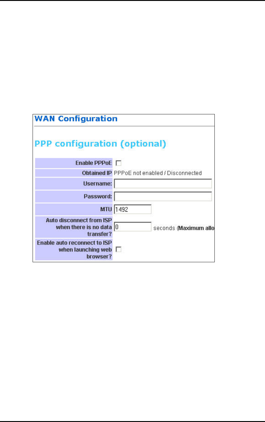
PPP Configuration
This section lets you configure the PPP dial-up settings. This part is configured if you connect the
WAN port to a ADSL modem.
Enable PPPoE: If you are using a ADSL modem, you have to enable PPPoE.
Obtained IP: This displays the IP of your WAN as given by the ADSL modem.
Username: Enter the username given by your Internet Service Provider.
Password: Enter the password given by your Internet Service Provider.
MTU: Maximum Transmission Unit indicates that packets larger than this size will be fragmented
before the transmission. Use the default 1492.
Auto disconnect from ISP when there is no data transfer?: Allows you to set a specific period
of time to disconnect from the Internet Service Provider. The factory default is 0, which means it
will never disconnect from Internet Service Provider.
Enable auto reconnect to ISP when launching web browser?: Router will auto-connect to
Internet Service Provider when user launches web browser on his PC.
Page 14
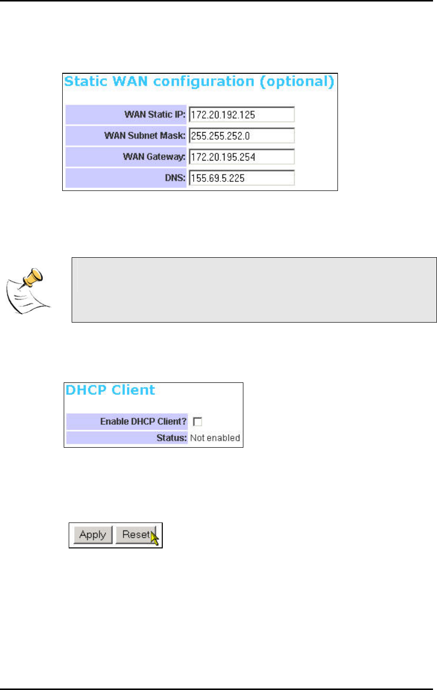
Static WAN Configuration
This section lets you configure Static WAN IP settings.
WAN Static IP: Enter the static IP address.
WAN Subnet Mask: Enter the subnet mask.
WAN Gateway: Enter the WAN Gateway IP.
DNS: Enter the DNS Server IP Address.
When in DHCP client mode, these 4 columns show the IP settings obtained
from the network.
DHCP Client
This section lets you configure the WAN port as a DHCP Client. This is the Factory Default mode.
Enable DHCP Client?: Select to enable WAN as a DHCP Client.
Status: This shows the status of the WAN port, whether it has obtained a IP lease or not.
Apply and Reset
After making the necessary changes, make sure you hit Apply and Reset.
Ensure that you do this for every updated page.
Page 15
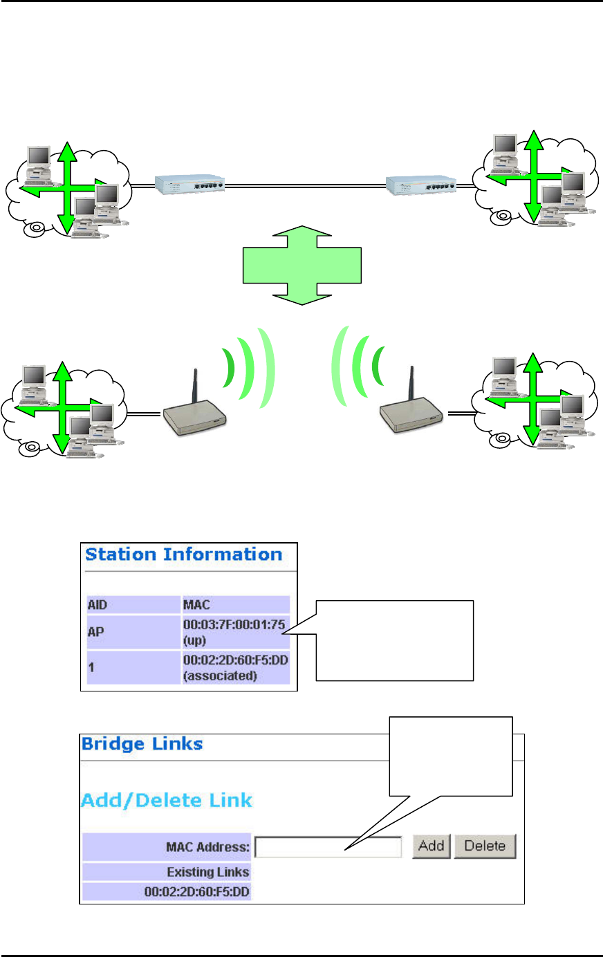
Bridge
The Router can also be used as a Wireless Bridge. This is used when it is not advisable to lay an
Ethernet line over a distance. Two routers can be set up to connect over this distance, acting as
the wired backbone.
Equivalent to:
LAN
LAN
Switch
Switch
Ethernet Cable
Wireless
Bridge
Router
LAN
LAN
Router
To establish the Bridge link,
1. Connect your PC to Router1’s LAN port. Do not connect anything to the WAN.
2. Get Router2’s MAC Address from Router2’s Station Information.
1. Log in to Router2’s
Station Information to
read the Router’s
MAC Address here.
3. Key Router2’s MAC Address into Router1.
2. Enter
Router2’s MAC
into Router1’s
Bridge Link.
Page 16

4. Change Router1’s LAN IP and subnet so that it can exist in LAN1.
5. Make sure that LAN1 and LAN2 are also in the same subnet!
6. Disable Router1’s DHCP Server.
7. Apply and Reboot.
8. Connect the LAN port of Router1 to LAN1.
9. Repeat the process for Router2.
MAC Address
MAC Address
Router
Router
10. Ensure that the SSID and Channel are the same for both Routers.
Page 17
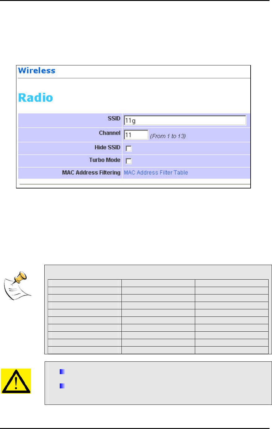
Wireless
This page lets you configure the Wireless settings.
There are 3 sections: Radio, Security, Advanced.
Radio Settings
SSID: Service Set Identifier. It is a sequence of characters that uniquely names a Wireless LAN.
This name allows PCs to connect to the correct Wireless Access Point when multiple Access
Points (or Wireless Routers) operate in the same location.
Channel: The radio channel number.
Hide SSID: When this is ticked, the router will not broadcast the SSID. Unwelcome PCs will not
be able to scan for the SSID of this Router, and they can only associate if they know exactly what
is the SSID.
Turbo Mode: When this mode is enabled, the Router would communicate with the CardBus at
108Mbps instead of 54Mbps. Turbo mode MUST also be enabled on the CardBus.
Take note of the effects of the following combinations.
Router CardBus Connection Speed
Non-turbo 11b 11Mbps
Non-turbo 11g 54Mbps
Non-turbo Turbo No connection!
Turbo 11b 11Mbps
Turbo 11g 54Mbps
Turbo Turbo 108Mbps
Router 802.11b Card Connection Speed
Non-turbo 11b 11Mbps
Turbo 11b No connection!
Turbo setting comes with some limitations. In Turbo mode,
All the devices automatically use Channel 6. Therefore, implementing
multiple cells is not possible with Turbo mode.
The network is more sensitive to interference. Wireless Access Points
operating nearby, regardless of channel, can cause interference to the
Turbo network.
Page 18
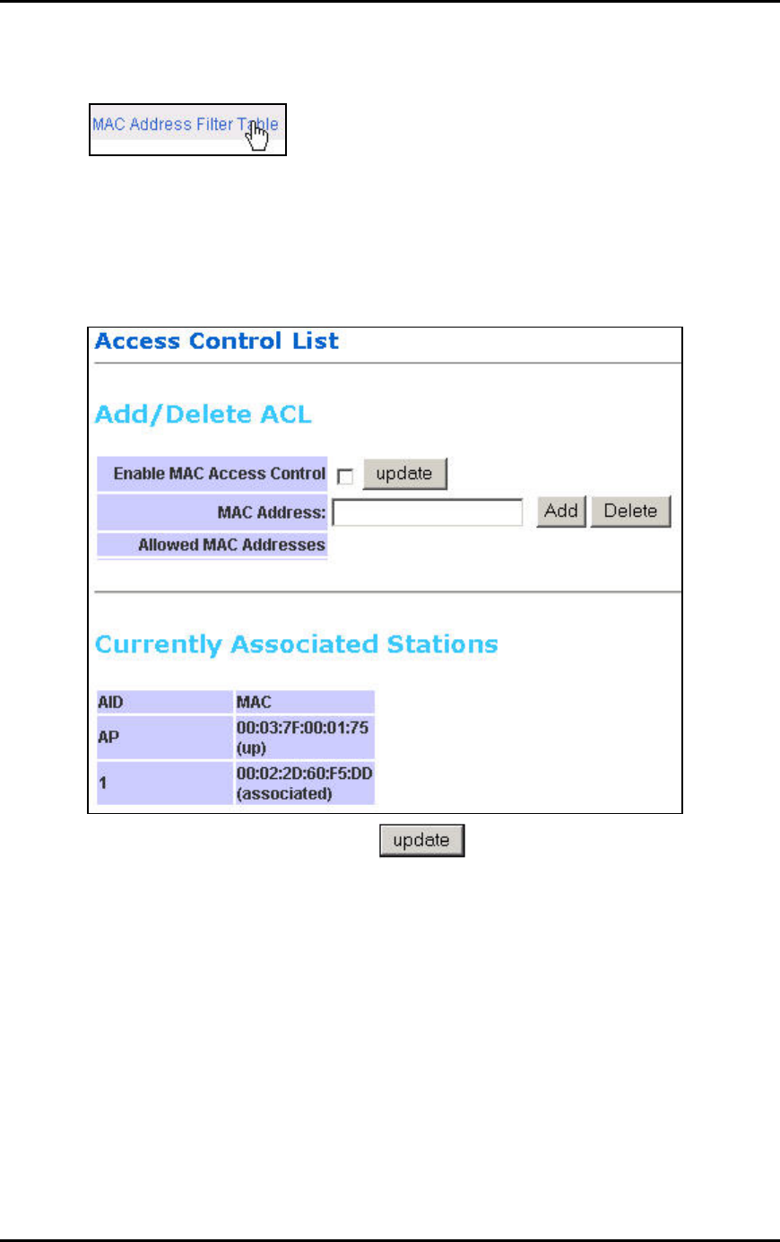
To enable MAC Address Filtering, click on the link MAC Address Filter Table. Only valid
computers (whose MAC addresses are in the MAC address table) would be allowed to access
the router.
Enable MAC Access Control: Tick the box to enable MAC Address Filtering.
MAC Address Add/Delete: Enter the MAC Address in the format 00:11:22:33:44:55 to be Added
or Deleted from the table.
Allowed MAC Addresses: Displays the MAC Addresses currently allowed.
Currently Associated Stations: Lists the MAC Addresses of the currently connected Cards. The
first MAC Address belongs to the Router, just for information. You can copy the cards’ MAC
Addresses from this list to paste into the “Add” or “Delete” list.
Update: Click Update to enable the new Table.
Page 19
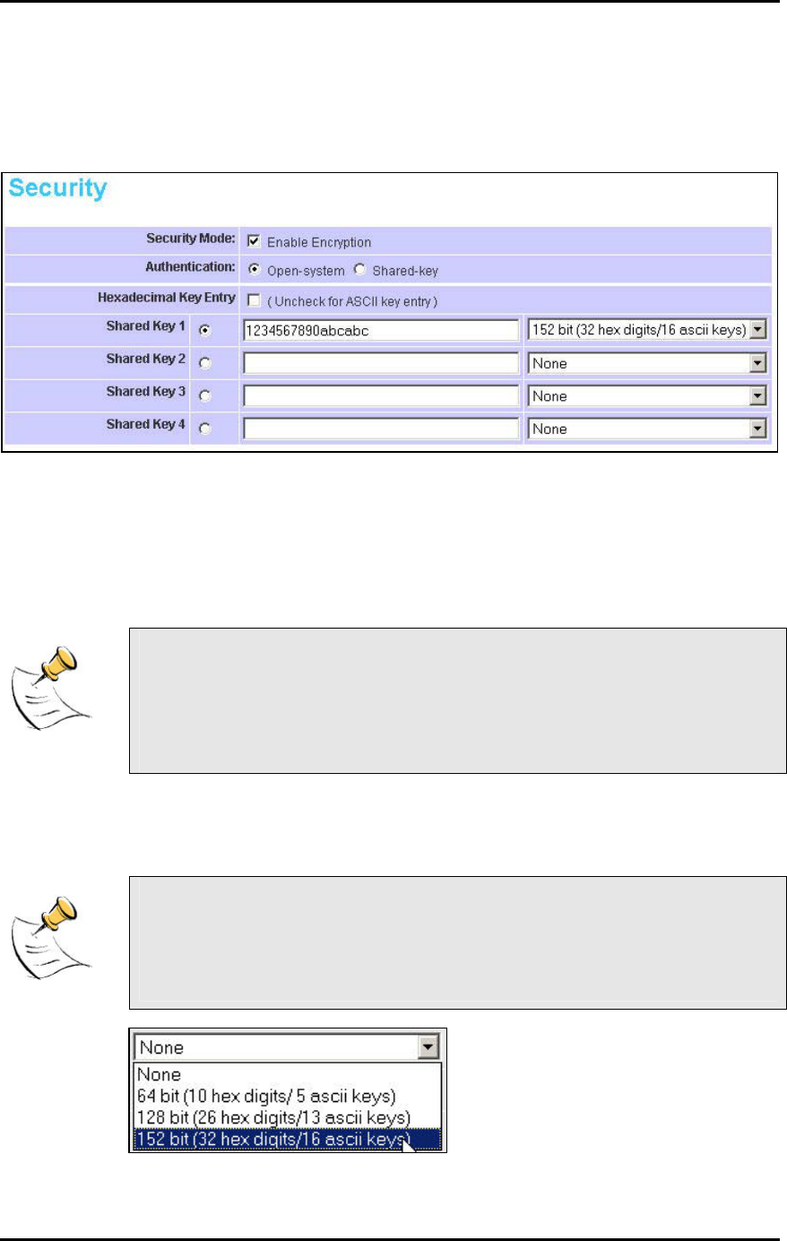
Security
This section allows you to configure wireless encryption to prevent unwelcome parties from
reading your traffic. Authentication can also be configured to block outsiders from accessing your
network.
Security Mode. Enable Encryption: Tick the box to enable the following suite of Encryption and
Authentication features.
Open-System: When chosen, the Key is not used for authentication. It is only used for
encryption. Open-System uses Static Keys for encryption. Static (Shared) Keys are never
changed, and a hacker can crack the key after a period of time.
Shared-Key: When chosen, the encryption Key is also used for authentication between the
Router and Client. Note that this system is also using Static Keys.
Open-System and Shared-Key work like the WEP system in 802.11b networks.
In fact, 802.11b (11Mbps) cards can turn on WEP and work with the Router
using either Open-System or Shared-Key.
Some cards do not support Shared-Key. Use Open-System for simple
management.
Hexadecimal Key Entry: Tick this box if you want to enter the Keys in hexadecimal format.
Otherwise, enter in ASCII format. ASCII is also called Alphanumeric in some systems. Use the
same key format for the Router and Client!
Hexadecimal Characters:
0,1,2,3,4,5,6,7,8,9 and a,b,c,d,e,f
ASCII Characters:
0,1,2,……8,9 and
a,b,c,d,………x,y,z
Page 20
Shared Key 1-4: For Open-System and Shared-Key, the Key is to be entered in the boxes. The
SAME Key must be entered in both the Router and Client. Take note that there is a different Key
length for a different number of encryption bits. 152 bits is the most secure, but make sure that
your Client card supports it. The last point to take note is that if you use Key 4 on the Router, you
must also use Key 4 on the Client, for example. The same logic applies for Keys 1-3.
In summary, the Keys must be
The same
The same length
The same number of bits chosen
The same format (Hex or ASCII)
The same location (1-4)
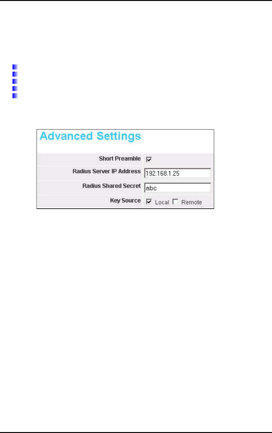
Advanced Settings
This section is for the configuration of some of the Advanced Settings.
Short Preamble: Tick the box to use Short Preamble in the Wireless LAN packet headers. Most
manufacturers implement long preambles. Even if there is a mismatch between the Router and
the card, they can still connect well and the mismatch may not be noticeable to most users. Do
not change this setting without seeking advice.
RADIUS Server IP Address: Enter the IP Address of the RADIUS Server (for 802.1x
authentication purposes). This is used only when you have a RADIUS Server and want to use it
for authentication. Almost all homes and many offices do not have a RADIUIS Server. These 3
settings are for advanced users only.
RADIUS Shared Secret: Enter the Shared Secret of the RADIUS Server. (Only if 802.1x protocol
is used.
Key Source: Specify the location of the key storage. (Only if 802.1x is used.)
Page 21
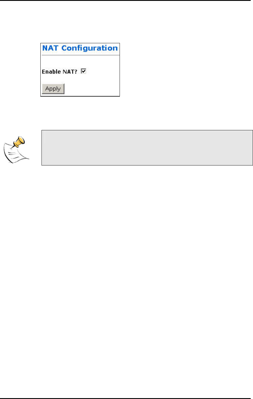
NAT
This page lets you configure your NAT (Network Address Translation).
Enable NAT?: Tick to enable NAT. NAT allows the sharing of one broadband connection
between multiple PCs. This setting is for advanced users only.
For almost all purposes, ENABLE the NAT.
Page 22
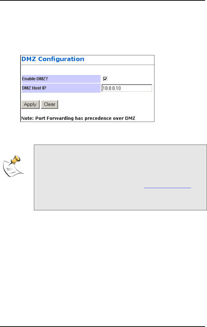
DMZ Configuration
The DMZ (De-Militarized Zone) Configuration page lets you map a local computer to this zone.
By default, the Router protects the PCs from the Internet. The local PCs can access the Internet
(WAN) but not vice versa. Local PCs are hidden behind the NAT and Firewall.
DMZ is used when you want to expose that PC to the Internet. For example, you want to set up a
Web Server or Game Server such that outsiders can access from the Internet.
Enable DMZ?: Tick to enable DMZ.
DMZ Host IP: Enter the local computer's (Web or Game Server) IP address.
All the ports of the PC in the DMZ would be exposed to the Internet. The DMZ
can be understood as a form of Port Forwarding where ALL the ports are
forwarded! DMZ is commonly used for hosting a Web Server.
For example, let’s say your Web Server in the DMZ has IP Address 10.0.0.10,
and the Router’s WAN has a IP Address of 222.222.222.222. To see your web
page, a person on the Internet only has to key in http://222.222.222.222 in his
web browser!
Note that Port Forwarding has precedence over DMZ. That means, if there were
a conflict between them, the Router would use the rule in Port Forwarding.
Page 23
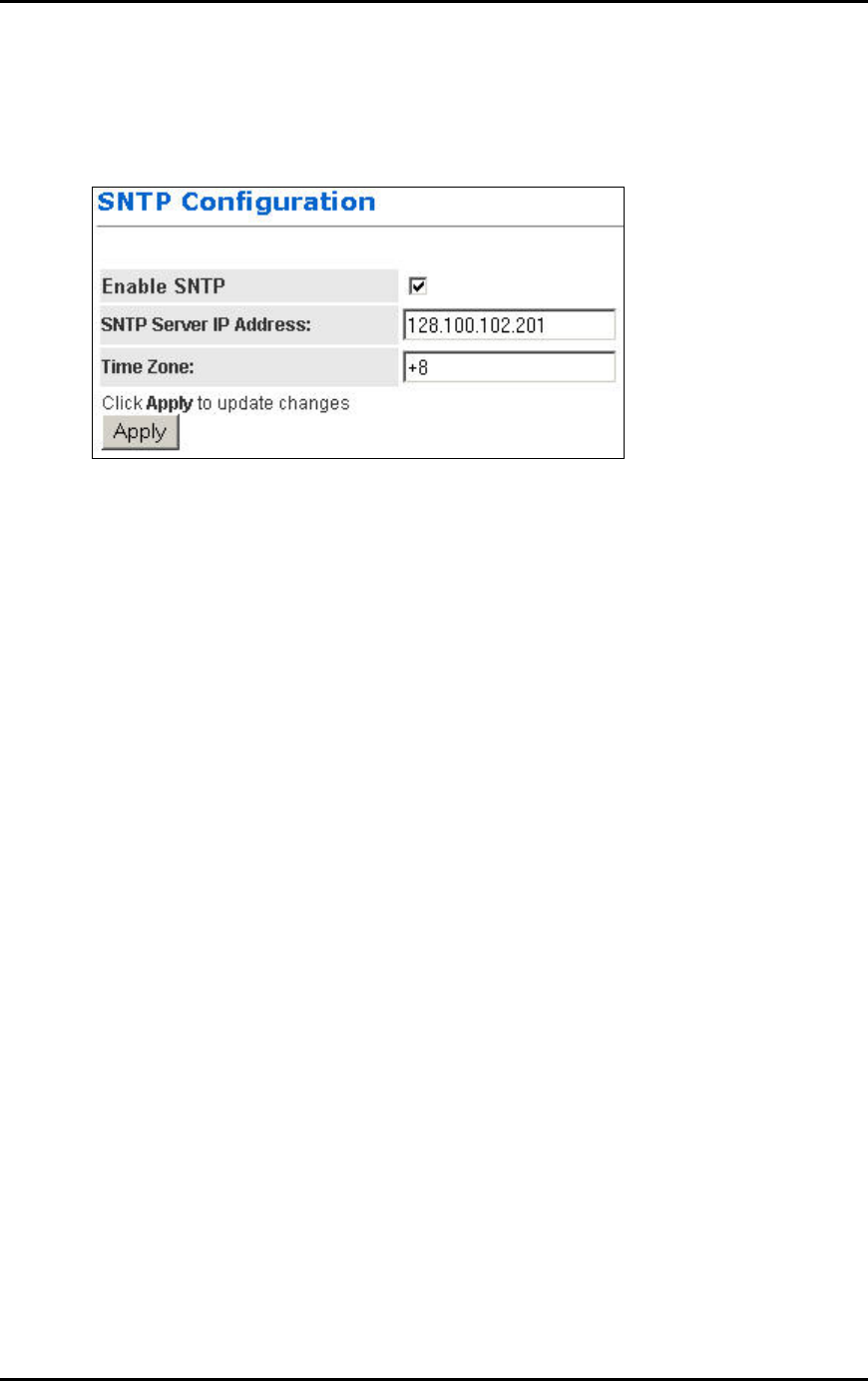
SNTP Configuration
This page allows you to configure the Router to automatically synchronize its time. SNTP (Simple
Network Time Protocol) is a standard that allows devices to synchronize their time according to
SNTP Servers on the Internet.
Enable SNTP: Click to enable the SNTP feature.
SNTP Server IP Address: Enter the IP Address of the SNTP Server on the Internet that you
want to use for synchronization.
Time Zone: Enter your local time zone.
Your System Log would be displayed with real-time provided by the SNTP feature. This setting is
for Advanced Users.
Page 24

Port Forwarding
This page allows you to configure Port Forwarding. This feature is used when you need to set up
Servers in the LAN. Traffic initiated from the WAN (Internet) is normally blocked. Port forwarding
allows the specific type of traffic to pass through the Router to reach the Server in the LAN.
Examples of these Servers are Web Servers and Game Servers.
Add new rule: This is where you specify the port to be map on the local computer.
ID: To append a serial number (0-19) to the particular Rule, so as to ease management.
Public Port: Refers to the port value on the WAN side.
Private Port: Refers to the port value on the LAN side.
Port Type: Select the type of protocol to be forwarded.
Host IP Address: Enter the IP address of the Local Server.
(Tips: Usually both Public Port and Private Port values are the same.)
Click Add This Rule button to add the rule.
Existing rules: This is the list of existing rules that have been specified on the router.
Remove rule: This is where you remove rules from the Router.
ID: Enter the ID number and click on the Remove button. The Rule is removed.
Page 25

Common application port values:
Application Port values Type
FTP 21 TCP
Web Server 80 TCP
Telnet 23 TCP
While all the ports of the PC in the DMZ are exposed to the Internet, Port
Forwarding only allows the ports that you specified to be opened up. DMZ can
be understood as a form of Port Forwarding where ALL the ports are forwarded.
DMZ is usually easier to set up, but Port Forwarding is more secure. For the
user accessing from the Internet, DMZ and Port Forwarding are basically similar
in function.
Page 26
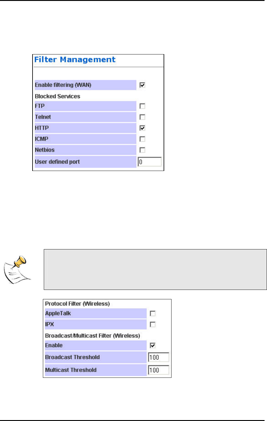
Filter
This page is for the configuration of filters to block unwanted traffic from WAN (Internet).
Enable filtering: Tick to enable the filtering features on this page.
Blocked Services: Tick beside the Service to block this Service from the Router.
FTP: Tick to disable FTP services (for firmware upgrade) from the Internet.
Telnet: Tick to disable telnet (a form of configuration tool) from the Internet.
HTTP: Tick to disable Web configuration by users in the Internet.
ICMP: Tick to disable Ping (a network troubleshooting tool) from the Internet.
NetBIOS: Tick to block NETBIOS (for Workgroup and File Sharing, etc) from the Internet.
User defined port: Configure a Service to be blocked even though it is not listed. Key in the
specific port number.
If you have a PC connected to the WAN side, you can key in the WAN IP in your
browser and access the Router’s configuration pages!
For security reasons, you may want to block HTTP (web) in the Filter.
Protocol Filter. AppleTalk: Block AppleTalk Protocol between WAN and WLAN.
Protocol Filter. IPX: Block IPX Protocol between WAN and WLAN.
Page 27

Enable: Tick to enable Packet Filtering by volume. These 2 settings are used to protect the
limited WLAN bandwidth.
Broadcast Threshold: Enter the number of Broadcast packets (in Packets/second) to be allowed
to travel between WAN and WLAN. Typical values can be 100.
Multicast Threshold: Enter the number of Multicast packets (in Packets/second) to be allowed to
travel between WAN and WLAN. Typical values can be 100.
Page 28
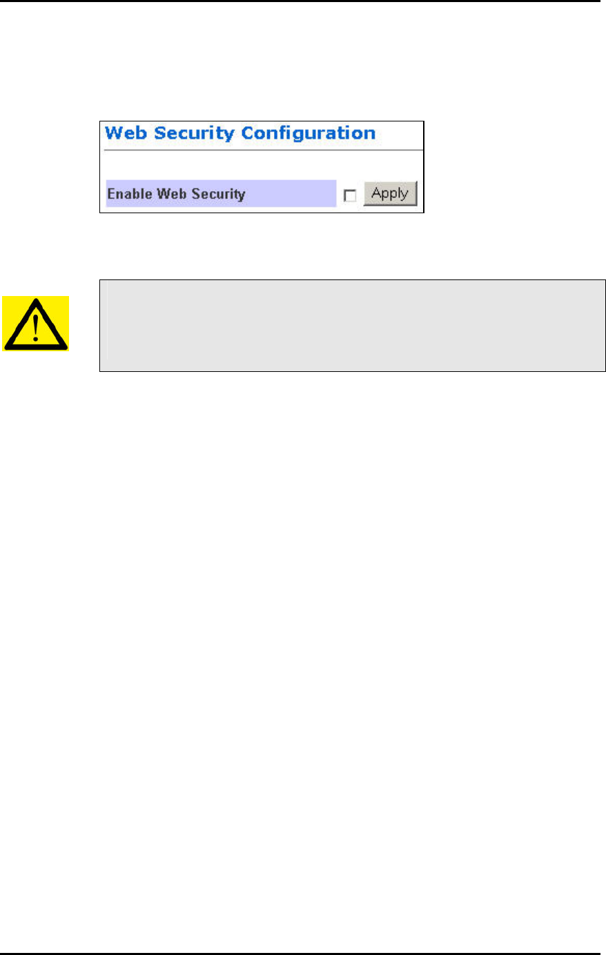
Web Security Configuration
This page allows you to configure Administrator’s security for the Router.
Enable Web Security: Tick the box and the Router would challenge every access to its
Configuration Webpage. This feature prevents unauthorized configuration of your Router.
By default, you are not challenged when you try to access the Configuration
pages. That means anyone with the correct WLAN settings can actually access
the Router and change its settings!
You are recommended to turn this feature on, and give yourself a
Administrator’s Username and Password.
Page 29
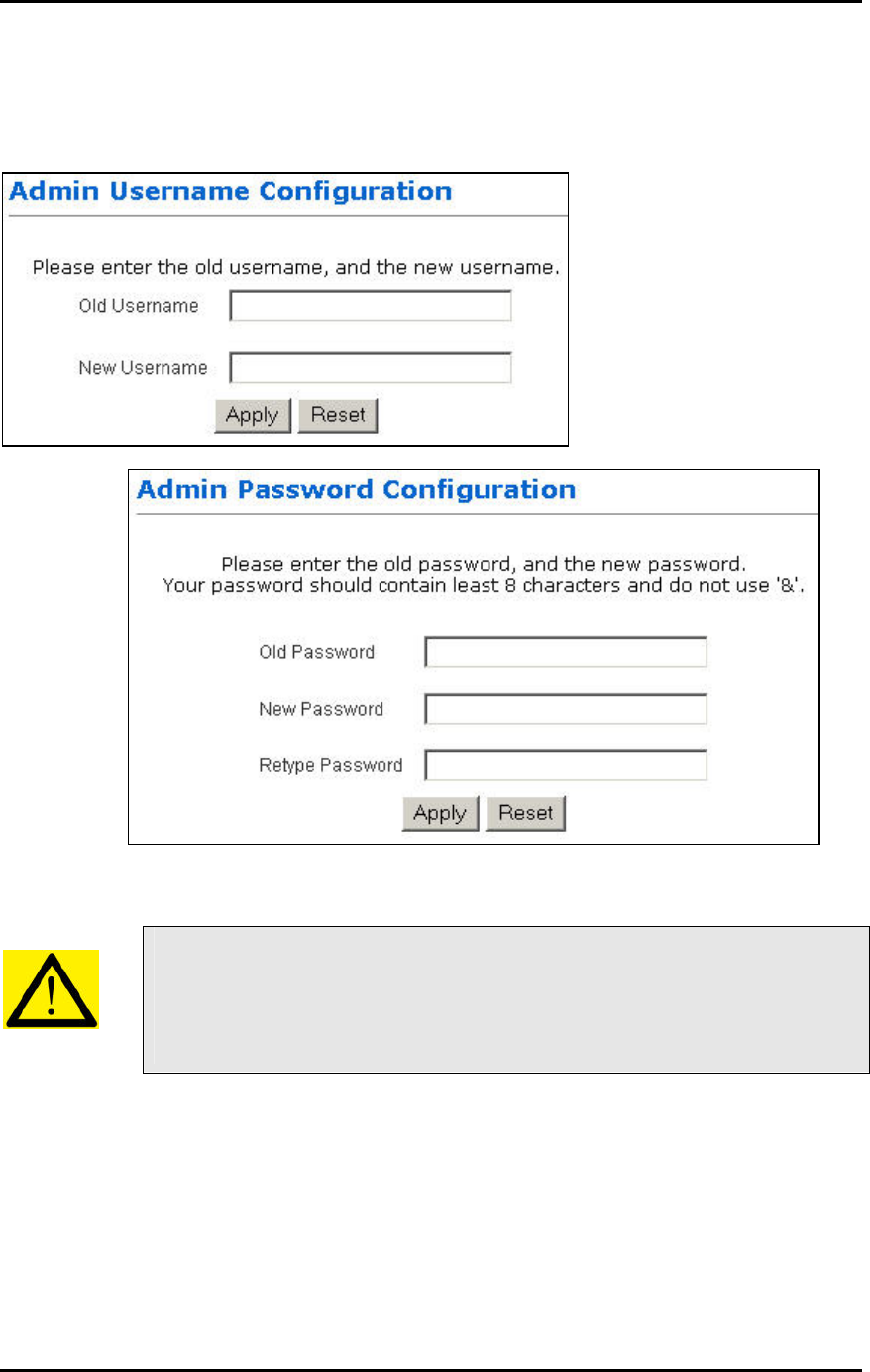
Admin Username and Password
These 2 pages allow you to change the Administrator’s Username and Password.
Every attempt to access the configuration pages of the router would be challenged, and the
Administrator’s Username and Password have to be used.
The default username is admin.
The default password is also admin.
After every Factory Reset, the Router reverts to this combination.
Page 30
Firmware Update
This page allows you to update the firmware (software) of the Router. New firmwares are issued
to improve the performance and add features to the product.
The Router is the FTP (File Transfer Protocol) client and your PC has to run a FTP Server using
a simple utility software.
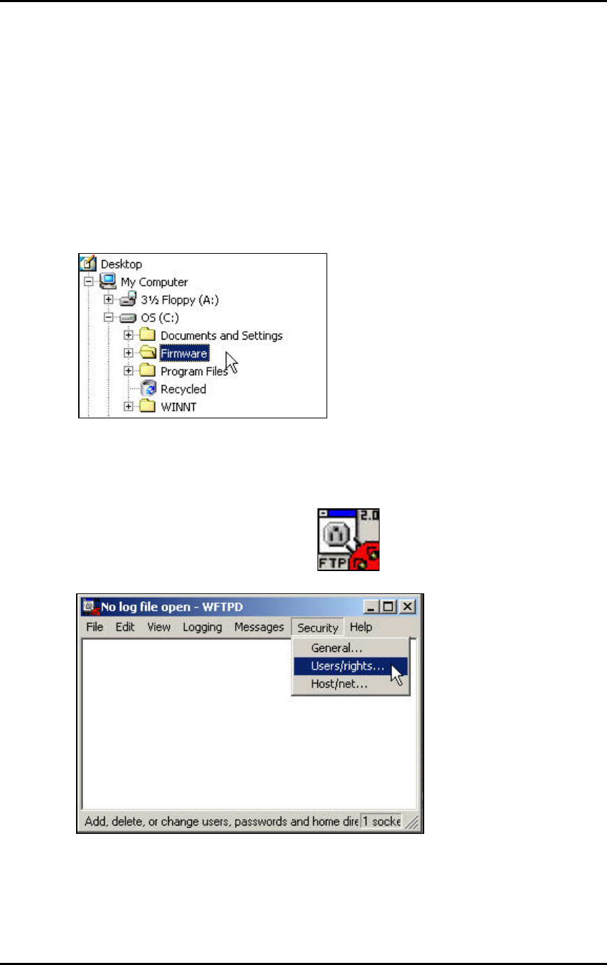
Step 1. Unzip Firmware Files
1. Create a directory in your C Drive hard disk and name it firmware.
2. Unzip the firmware files and save them into your new directory c:\firmware\
Step 2. Set up FTP Server
1. Run the software called WFTPD32.
2. Click Users/rights.
Page 31
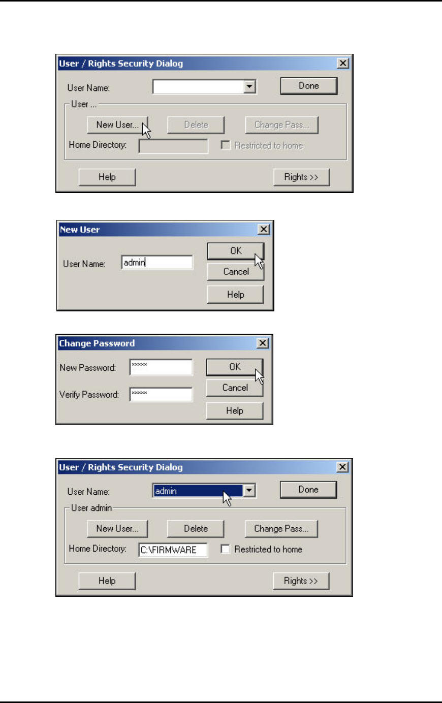
3. We have to Create a new user that has the name and password “admin”.
4. Enter the User Name as admin.
5. Enter the password twice as admin.
6. Type in c:\firmware as the Home Directory.
7. Click Done.
The FTP Server is now set up on your PC. You can proceed to Step 3.
The account has already been set up. In future, you would only need to do Step 1 and 2 and
select the account admin, instead of default or anonymous.
Page 32
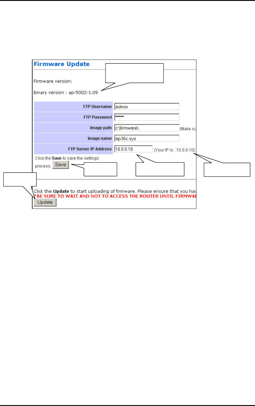
Step 3. Update Firmware
1. Leave the original settings on the page intact. They have been pre-configured for
you.
2. If you have accidentally changed the settings, configure using the picture below. The
FTP Password is admin.
Current firmware
version.
4. Click.
3. Click. 1. Read here.
2. Enter here.
3. Enter your PC’s IP Address. To help you, the Router suggests it to you on the web
page.
4. Save the settings.
5. Click Update and wait at least 40 seconds rebooting the Router.
Your firmware has been updated. After reboot, check that the version number has indeed
changed.
Page 33
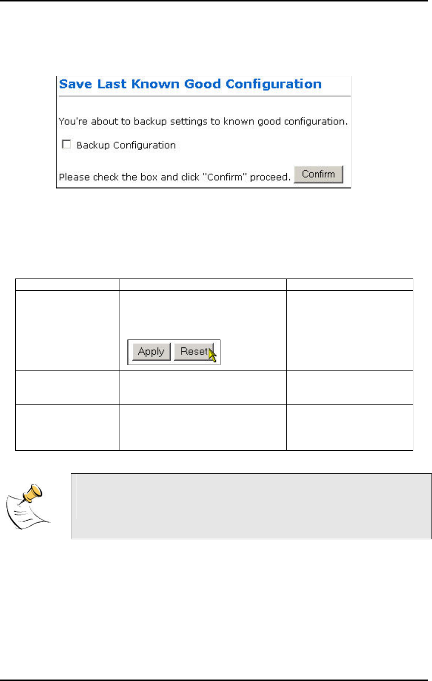
Save Configuration
This page allows you to save a “Good” Configuration into the Router’s memory.
After you have successfully configured the Router, you can save this “Good Config” into memory.
You can retrieve this “Good Config” later, if you have messed up some settings and do not know
what was the previous working setting. If you have even forgotten the password to get into the
configuration pages, you would have to do a Factory Reset to the Router.
There are 3 levels of configuration settings in the Router.
Saved/Updated by: Loaded when:
Running Config Every time you make a change and
click Apply, it is saved into Running
Config. The changes take effect
after a power on/off.
Every power up.
Good Config Manually saving the settings in
“Save Last Known Good
Configuration”.
Manually restoring it in the
“Restore Settings” page.
Factory Default There is no way to change the
Factory Default settings!
When you press the
Reset button at the back
of the Router for 10
seconds.
Most users would not need this “Good Config” feature.
Just remember to Apply and Reboot every time you make a change.
Page 34
PC CONFIGURATION
The Router’s function is to connect multiple PCs to the Internet. In addition to configuring the
Router, the PCs’ IP settings would also need to be configured.
It is easiest to use DHCP client for the PCs. This is also the default whenever you:
a. Install a new Wireless PCMCIA/Cardbus card, or
b. When you plug a Ethernet cable into your PC for the first time.
Fortunately, in default mode, the Router’s DHCP Server is on. This means that when you buy a
new Router and install a new Wireless Card, the IP settings on the PC are already correct!
In the event that you need to troubleshoot the IP settings, the easiest method is:
a. Perform a Hardware Reset to the Router, and
b. Perform a following to configure Automatic IP (DHCP Client) on the PC.
DHCP IP Address
The steps outlined are applicable for Windows PCs. The GUI for Windows 98SE and ME may
look slightly different, but the steps are the same.
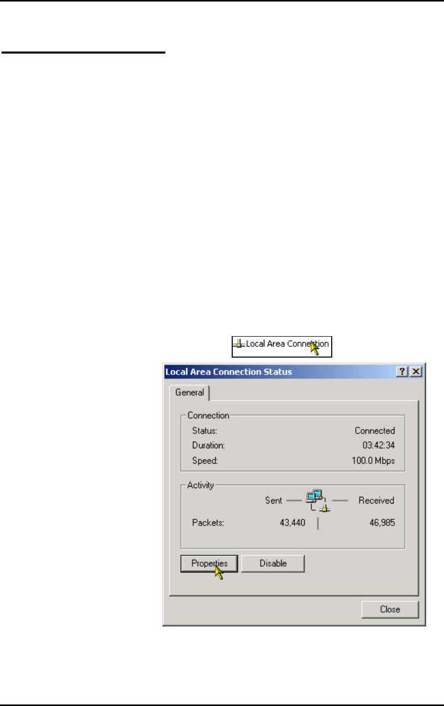
1. Connect the PC to the Router. This can be via Ethernet or Wireless. Do not connect
any other networking devices! Do not connect the modem to the PC!
2. Go to Start >> Settings >> Control Panel >> Network and Dial-Up Connections
3. Double-click Local Area Connection.
4. Click on Properties.
Page 35
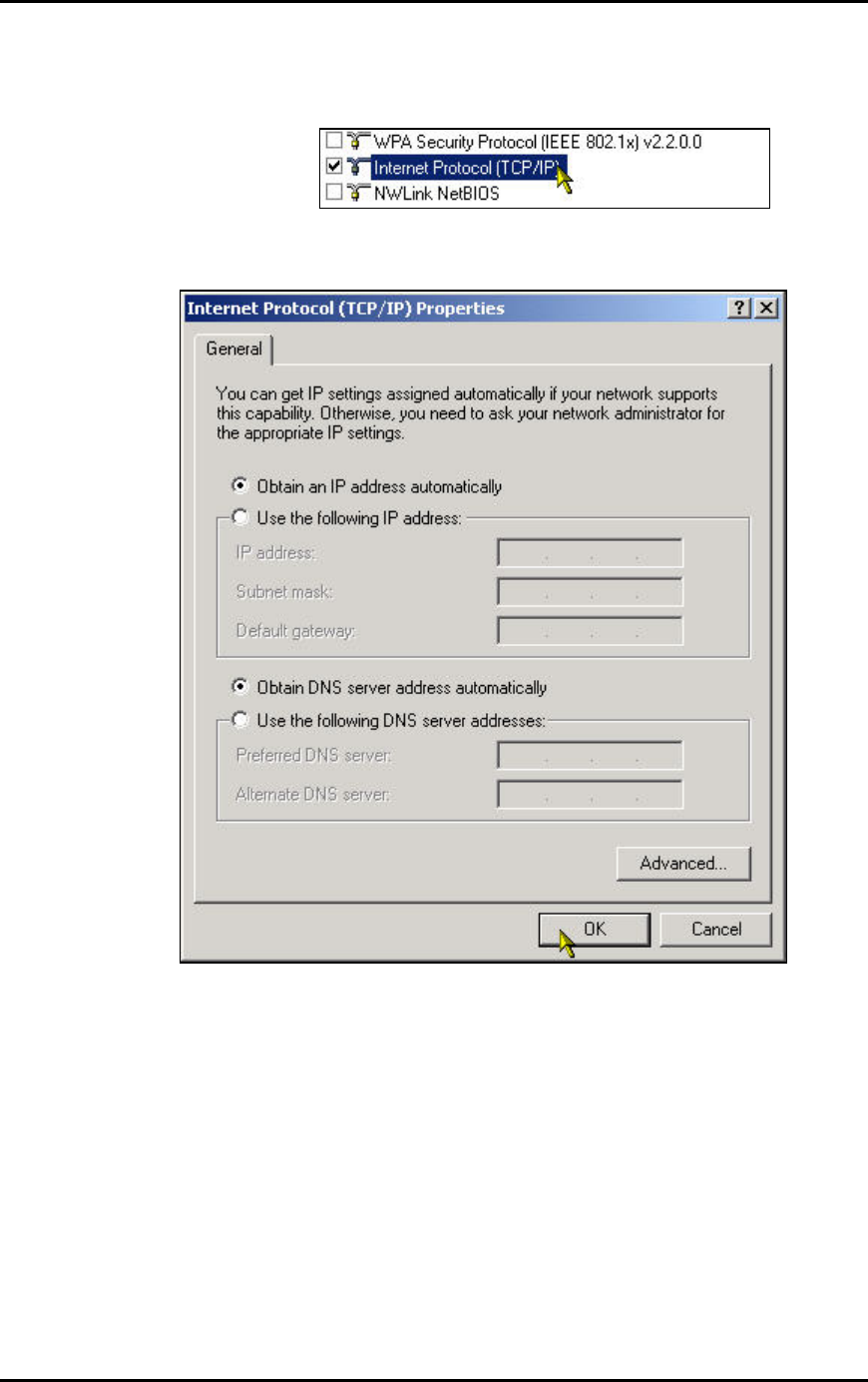
5. In the box, click on Internet Protocol (TCP/IP). Make sure there is a tick in the box for
TCP/IP.
6. Use automatic for both the settings. Click OK and close all windows.
7. Windows 98SE and ME may prompt you for a reboot.
DHCP Client has been set up on your PC. Make sure you do a Factory Reset to the Router and
configure your broadband account again.
Page 36
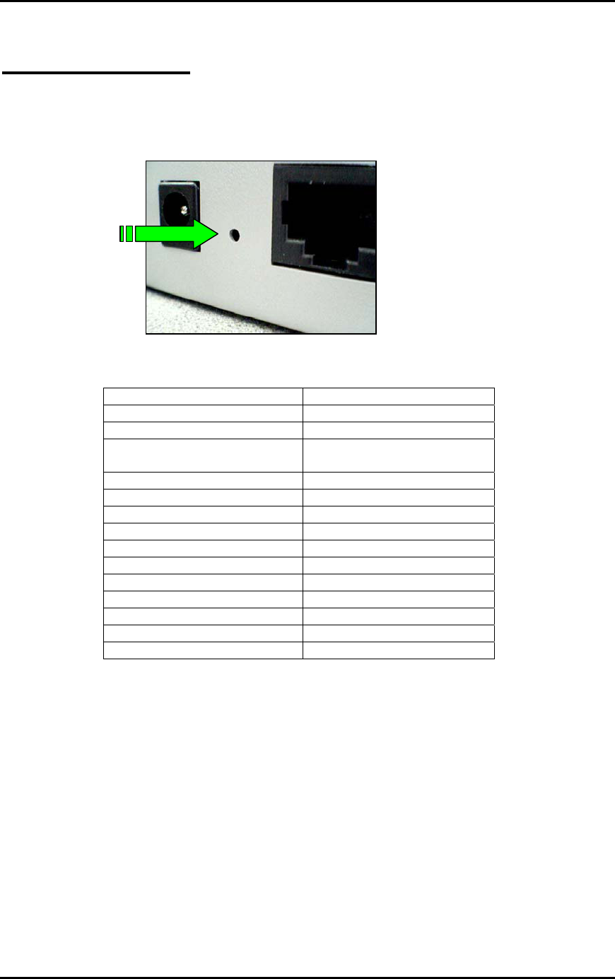
FACTORY RESET
When you have wrongly configured the Router and wish to start all over again, you can perform a
Factory Reset to restore the Router to its original state. Simply use a paper clip or any pointed
object to press in the hole for 5-10 seconds and release.
The Router would be reset to its original Factory Default configuration:
Router’s Feature Factory Default
WAN WAN is a DHCP client
LAN IP (including WLAN) 10.0.0.1
DHCP Server (including
WLAN)
On.
Lease starts from 10.0.0.2
System Log Off
SSID 11g
Channel 11
Turbo mode Off
MAC Address Control Off
Encryption Off
NAT On
DMZ Off
Port Forwarding Off
Filtering Off. (No block)
Administrator’s Security Off. (No password needed)
Page 37