RFNet Technologies AP1062 ACCESS POINT AND BRIDGE User Manual UG Outdoor AP V01 Intellinet 06172008
RFNet Technologies Pte Ltd ACCESS POINT AND BRIDGE UG Outdoor AP V01 Intellinet 06172008
UserManual.wiki
>
RFNet Technologies
>
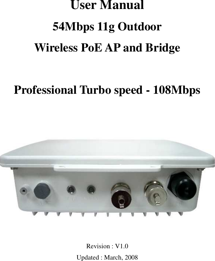
AP1062 User Manual
Manual
Navigation menu
Upload a User Manual
Namespaces
Wiki Guide
HTML
PDF
Info
Views
User Manual
Discussion / Help
Navigation