RFNet Technologies AP1068 2.4GHz 802.11b/g Outdoor AP-Repeater-Bridge User Manual
RFNet Technologies Pte Ltd 2.4GHz 802.11b/g Outdoor AP-Repeater-Bridge
UserManual.wiki
>
RFNet Technologies
>
AP1068 User Manual
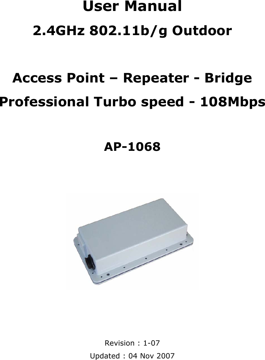
User Manual
Navigation menu
Upload a User Manual
Namespaces
Wiki Guide
HTML
PDF
Info
Views
User Manual
Discussion / Help
Navigation