RFNet Technologies AP2061 Wireless Access Point User Manual ap2061 r1 08
RFNet Technologies Pte Ltd Wireless Access Point ap2061 r1 08
UserManual.wiki
>
RFNet Technologies
>
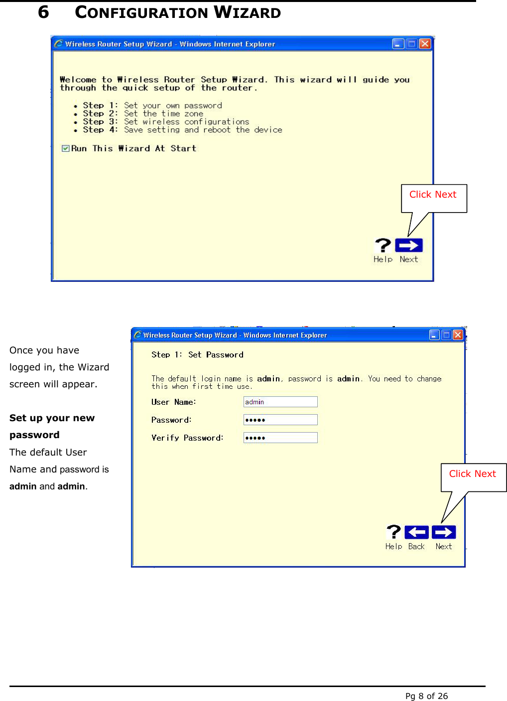
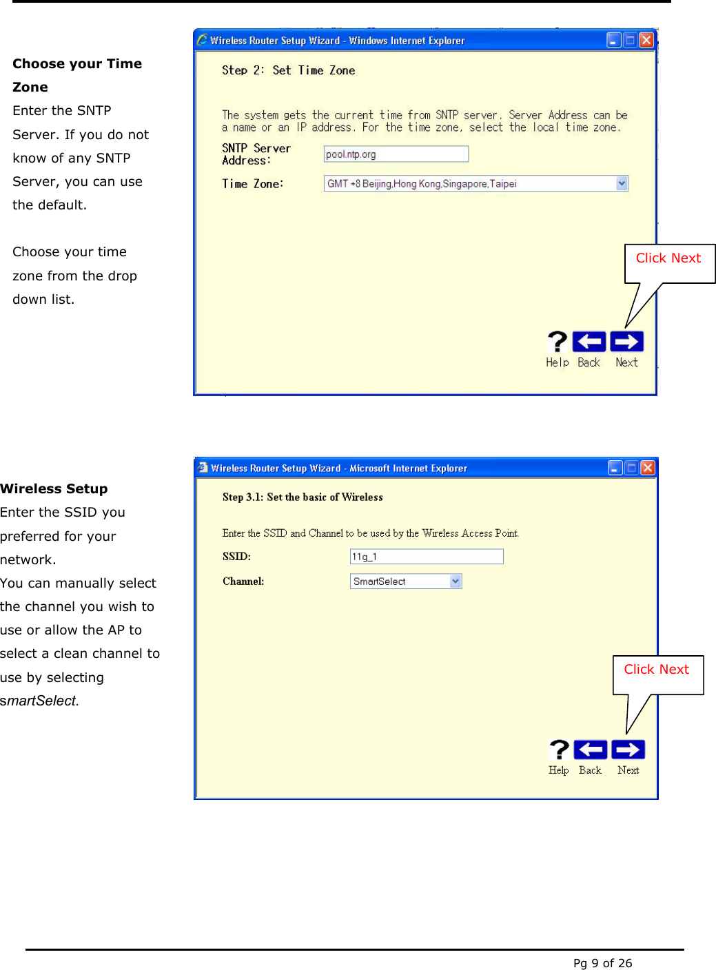
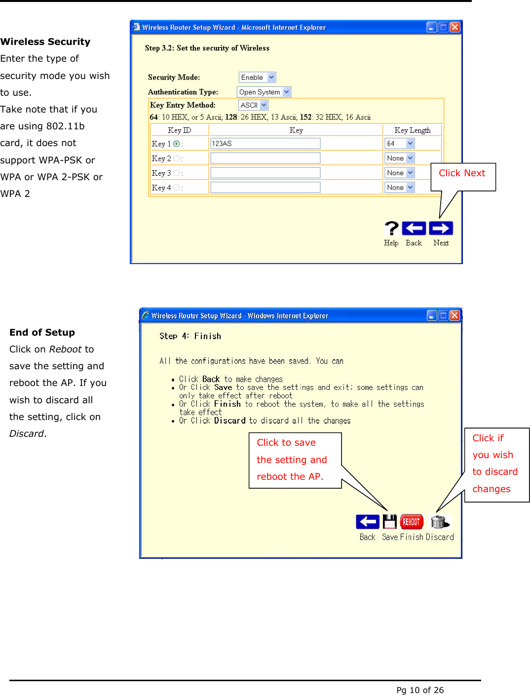
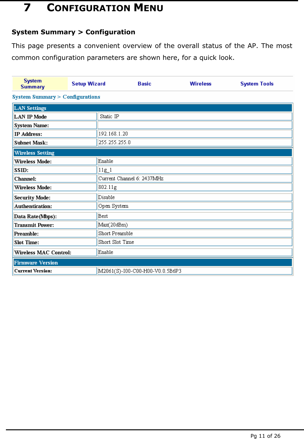
AP2061 User Manual
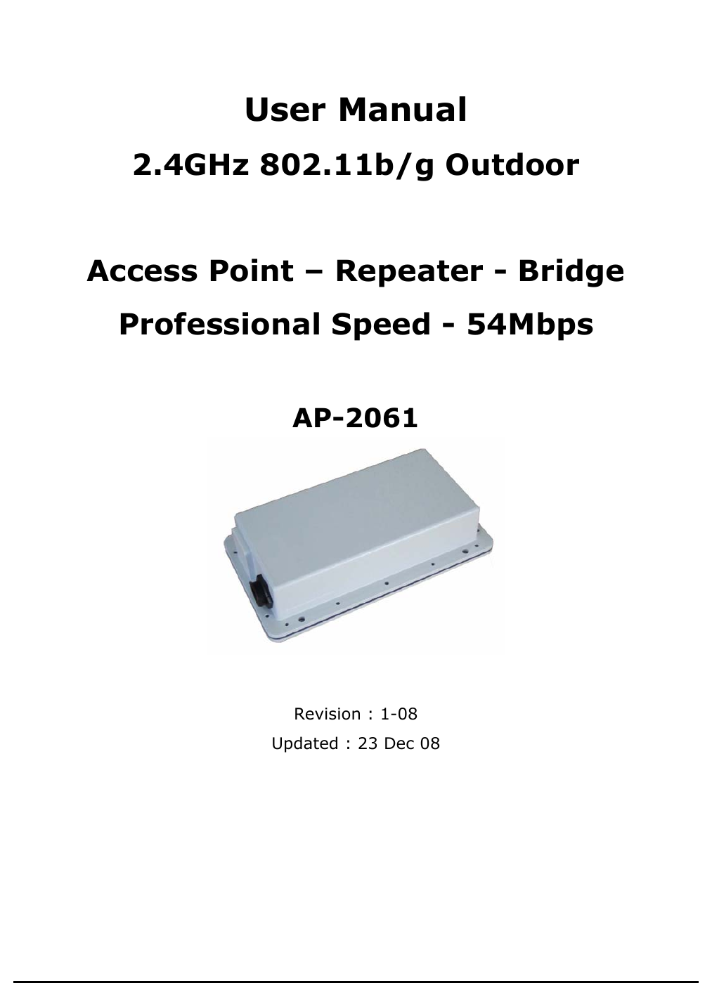
User Manual
Navigation menu
Upload a User Manual
Namespaces
Wiki Guide
HTML
PDF
Info
Views
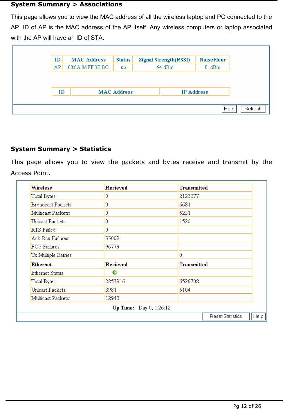
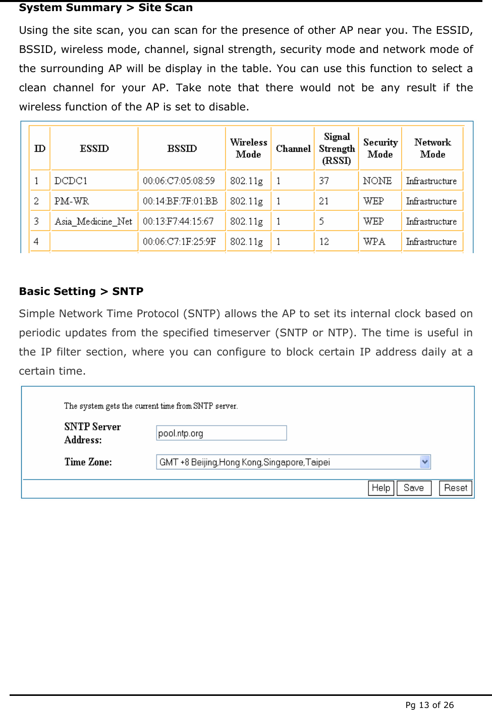
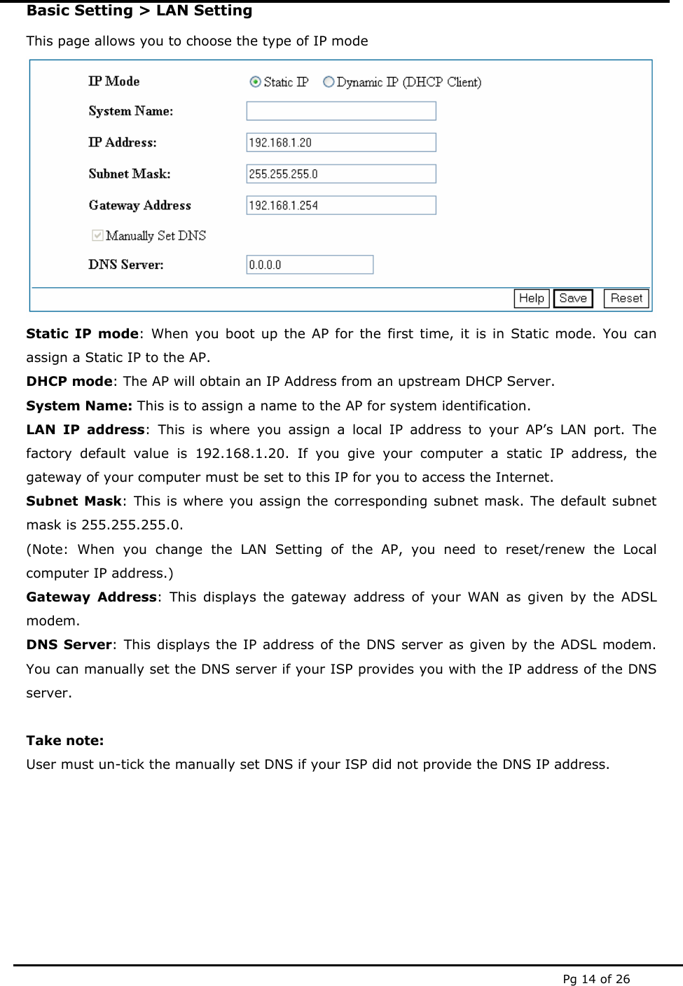
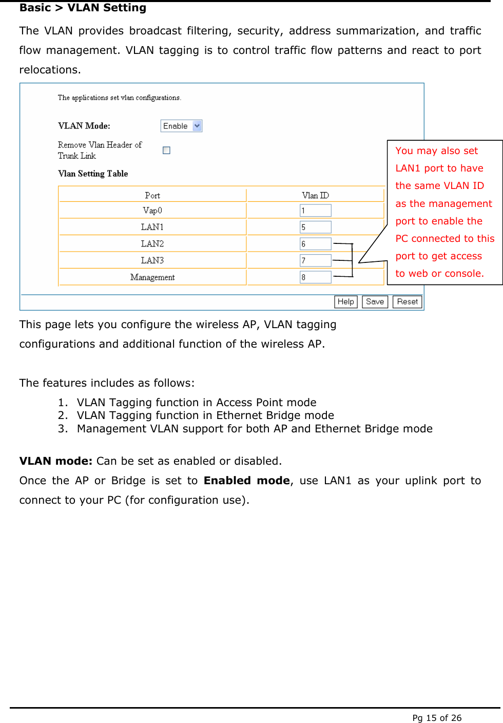
User Manual
Discussion / Help
Navigation