RGB Wireless Applications TX01 Security Transmitter User Manual DigiGuard2UsersGuide
RGB Wireless Applications, Inc. Security Transmitter DigiGuard2UsersGuide
users manual

RGB Wireless Applications, Inc.
DigiGuard™ Door Alarm
Installation and Operation
Guide
DigiGuard™ Door Alarm
Installation and Operation
Guide
COPYRIGHT
Information in this document is subject to change without notice excluding the required FCC notices. No
part of this publication may be reproduced, stored in a retrieval system, or transmitted in any form or any
means electronic or mechanical, including photocopying and recording, for any purpose other than the
purchaser’s personal use, without the written permission of RGB Wireless Applications, Inc.
PUBLISHED BY
RGB Wireless Applications, Inc © 2005 All Rights Reserved.
No. 1200-182 Rev. 1.0 05/09/2005 Printed in the United States of America
WARNING! This device operates under Part 15 of the FCC
rules. Any modifications to this device not expressly authorized
by RGB Wireless Applications, Inc. will void the user’s authority
to operate this device. This device is not field serviceable and
must be returned to the factory for any repairs. Please contact
RGB Wireless Applications if any problems are experienced with
this product.
Warranty and Special Provisions
LIMITED WARRANTY. Manufacturer warrants that the Software will perform substantially in accordance
with the accompanying written materials for a period of three hundred sixty (360) days from the date of
purchase.
CUSTOMER REMEDIES. Manufacturer’s entire liability and your exclusive remedy shall be, at
Manufacturer’s option, either (a) return of the price paid, or (b) repair or replacement of the Software that does
not meet this Limited Warranty and which is returned to the Manufacturer with a copy of your receipt. This
Limited Warranty is void if failure of this Software has resulted from accident, abuse, or misapplication. Any
replacement Software will be warranted for the remainder of the original warranty period or thirty (30) days,
whichever is longer.
NO OTHER WARRANTIES. To the maximum extent permitted by applicable law, the Manufacturer and
its suppliers disclaim all other warranties, either express or implied, including but not limited to implied
warranties of merchantability and fitness for a particular purpose, with regard to the Software, the
accompanying written materials, and any accompanying hardware. This Limited Warranty gives you specific
legal rights. You may have others which vary from state/jurisdiction to state/jurisdiction.
NO LIABILITY FOR CONSEQUENTIAL DAMAGES. To the maximum extent permitted by applicable
law, in no event shall Manufacturer or its suppliers be liable for any damages whatsoever (including without
limitation, direct or indirect damages for personal injury, loss of business profits, business interruptions, loss of
business information, or any other pecuniary loss) arising out of the use of or inability to use this product, even
if Manufacturer has been advised of the possibility of such damages. In any case, Manufacturer’s and its
suppliers’ entire liability under any provision of this agreement shall be limited to the amount actually paid for
the Software. Because some states/ jurisdictions do not allow the exclusion or limitation of liability for
consequential or incidental damages, the above limitation may not apply
Terms and Conditions of Purchase
PURCHASER understands that unless otherwise specified in writing and
agreed to by both parties, neither installation nor the warranty thereof, is
included in this Agreement.

Figure 1-2
Pre-Installation Considerations Site Design and Placement of Devices
Planning must be done to ensure that all Door Transmitters can communicate with at least one
Repeater or the Receiver. Repeaters are used to capture signals that cannot reach the Receiver
directly. The Receivers and Repeaters are powered by 12VDC. The Door Transmitters use a lithium
battery with a ten year calculated battery life.
Each Door Transmitter is uniquely numbered and marked with a Serial Number on the back of
the case. As each Transmitter is installed, the Serial Number MUST be recorded in conjunction
with the Unit number it is installed on. This information will be required to set up the DigiGate-
700™ software for correct reporting.
Door Transmitters are normally mounted in the upper left corner of the door or on the opposite side
of the
frame from the door latch. Repeaters can be mounted inside or outside of the building, depending
on the unit door locations. Each Repeater requires 120/240 VAC power. The Repeaters should be
mounted so the antenna is at approximately the same height or slightly above the Door
Transmitters. This provides the best coverage of the facility, and requires the least number of
Repeaters for the installation.
The Receiver communicates with the System Controller over an RS-485 communication line.
Normally the Receiver would be located in or near the office.

Included in this Chapter
Introduction.....................................................................Description of Door Transmitter
Mounting the Door Transmitter and Magnet...................... Roll-Up Doors Garage Type
Panel Roll-Up Doors Swing Doors
Battery Connection and Replacement ........................ Installing the Battery
Replacing the Battery
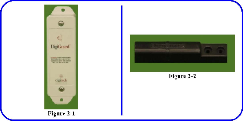
Introduction The Door Transmitter, Figure 2-1, is
housed in an environmental plastic enclosure. The enclosure has been designed for outdoor use, and
has a UV inhibitor in the material. The enclosure is also moisture sealed with a gasket between the
cover and case of the enclosure.
The Door Transmitter is equipped with a tamper switch. Removing the cover of the Transmitter or
placing another magnet near the case will trigger the tamper alarm.
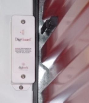
The Transmitter must be mounted on the door frame with the Magnet, Figure 2-2, mounted on the
door. The proper alignment of these two components will ensure that the reed switch array will
operate correctly when the door is opened and the Magnet moves away from the Transmitter.
Proper orientation of the door switch will also ensure that the antenna is oriented correctly for
maximum antenna gain. The magnet is a heavy duty design which allows for greater tolerance,
preventing the possibility of false alarms from minor movements of the door.
The Transmitter/Magnet assembly should be mounted on the opposite side of the door from the
door hasp on a roll-up door to avoid hitting the Transmitter with the hasp. On swing doors, mount
the Transmitter/ Magnet assembly on the opposite side of the door from the hinges to provide
adequate separation of the Magnet on opening of the door. Mounting is shown on the left of a roll-
up door since most hasps are mounted on the right. On swing doors, the mounting is shown on the
right since most hinges are on the left.
If the facility’s configuration is different, rotate the entire assembly, Transmitter and Magnet,
keeping the orientation of the Magnet and Transmitter the same.
NOTE: If the site has garage type doors or other non standard doors, or any damaged doors or
frames, notify RGB Wireless Applications at (540) 786-0621

Figure 2-3 Figure 2-4
Mounting the Door Transmitter and Magnet
Roll Up Doors
1 When installing the Door Transmitter on roll 3. Use the DigiGuard™ mounting template
(P/N up doors, it should be mounted vertically in 1420-200) for placement and marking of the the
upper left corner of the door jamb. The holes to mount both the Transmitter and the Magnet is
mounted horizontally on the door Magnet. Figure 2-4 and aligned with the ridge on the Transmitter
4. Place the larger vertical bar on the door frame case. Figure 2-3 with the horizontal smaller bar in
one of the
2 The Magnet mounts horizontally in a recess on recesses on the door approximately 3”
below the corrugated door to provide clearance when the top of the door frame. the door rolls up.
Figure 2-3
Note: If the door hasp is mounted on the left
side of the door, invert the mounting
template and use it upside down on the right
side of the door. The bar in the recess will
be lower on the door than stated in Step 4.
5. Mark all holes and remove the template.
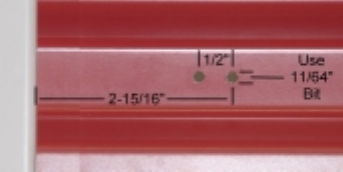
Figure 2-5
1 Center punch all the marks to keep the drill from walking off the marks.
2 Drill the holes for the Magnet with a 11/64” bit. Figure 2-5
CAUTION: DO NOT use the Magnet as a template for the drill. The close tolerance on
these rivet holes is to insure a stable mounting of the Magnet to the door. Drilling through
the rivet holes in the Magnet will enlarge them and leave the Magnet less than ideally
secure and stable.
1 Place a rivet (Digitech P/N 2840-008, supplied) in each hole on the Magnet and place it
through the drilled hole in the door.
2 Finish securing the Magnet with the rivets.
Figure 2-6
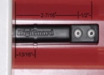
Note: Figure 2-6 shows the proper mounting of the Magnet for optimum performance. The
vertical ridge down the center of the Magnet should be aligned in the center of the Trans-mitter
case. The Magnet has been designed to be easily mounted on existing doors. The rivet holes are
located on the right so the Magnet can be mounted with minimum effort. The rivet holes on the
Magnets have very close tolerances to provide tight, stable installation. Do not substitute the
size of the rivets shipped with the Magnets and do not use the Magnet as a jig for drilling.
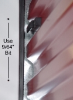
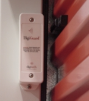
Figure 2-7
10. If mounting the Transmitter on an aluminum or wood surface, drill the holes using a 9/64” bit.
If the mounting surface is not metal or wood, drill the hole 1/4” to hold an appropriate anchor
(not supplied) for the #8 screw.
Figure 2-7 Figure 2-8
1 Record the Serial Number of the Transmitter and the unit number for later entry into the
DigiGate-700™ software. See Appendix B
2 Secure the Transmitter using the #8 x 3/4” screws supplied with the case. Figure 2-8
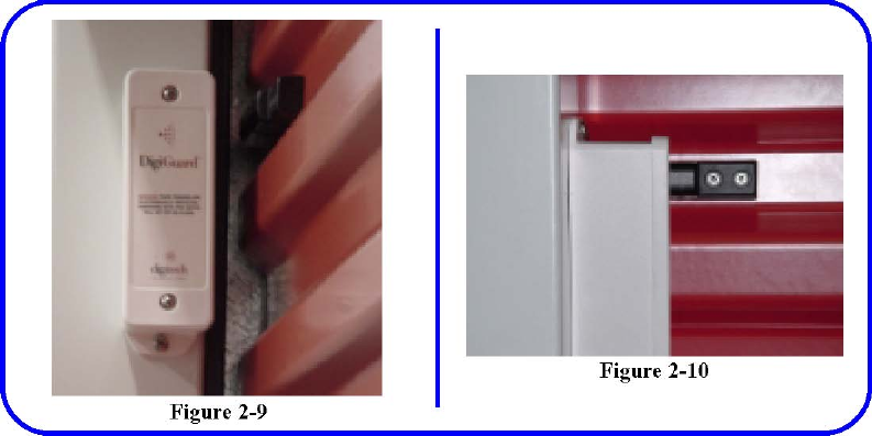
NOTE: Placing the Magnet closer than
1/ 13. Figures 2-9 and Figure 2-10
show the
2” to the Transmitter will affect the
tamper completed installation.
alarm. The Magnet should be from
5/8” to
3/4” from the Transmitter when the
door is
fully closed.

Figure 2-12
Garage Type Panel Roll-Up Doors
1. Installing the Door Transmitters on garage 3. The Magnet cannot mount behind the door type
panels is the same as standard roll-up frame as it did on the standard roll up door. doors with
the Transmitter and Magnet on the 4. Since less of the magnet is positioned behind
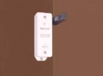
opposite side from the door hasp.
NOTE: If the door hasp is mounted on the left side of the door, mount the Transmitter
upside down on the right side of the door as in the standard roll-up door installation.
The differences are:
2. The Transmitter and Magnet should be mounted in the vertical center of a panel to prevent
knocking the Magnet off the door when it is raised. Mounting it near the top or bottom edge of
the panel will bring it too close to the top of the door frame when the door is rolled up. Figure
2-11 the Transmitter, the magnetic strength is less and the Transmitter should be mounted with
a gap about 1/4” less than a standard roll-up door. Figure 2-12
NOTE: The Transmitter should be approximately 1/2” to 5/8” from the Magnet and should
be tested to insure correct operation.
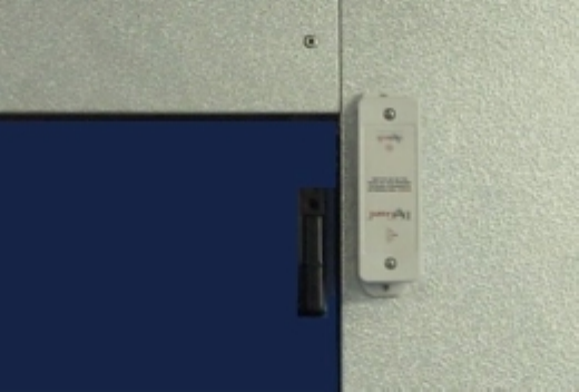
Figure 2-13
Swing Doors
When installing the Door Transmitter on swing doors, the Transmitter should be mounted vertically
and inverted (upside down for the right side door frame) or in its standard configuration for the left
side door frame. The Transmitter and Magnet should be mounted on the side of the door opposite
from the hinges (the latch side). The gap between the Transmitter and the Magnet should be 1/2
inch and as close to the top of the door as possible. The ridge on the Magnet should align about 1/4”
above (toward the center of the transmitter) the ridge on the Transmitter case.
Mounting the Transmitter and Magnet
1. Mount the Transmitter vertically at the 6. Drill these holes using a 9/64” bit. upper corner of
the door frame, as stated 7. Record the Serial Number of the Transmit-above, opposite the
hinged side of the ter and the unit number for later entry into
door. The edge of the case should be the DigiGate-700™ software.
approximately 1/4” from the edge of the 8. Secure the Transmitter using the #8 x 3/4” door frame. screws
supplied with the case.
2. The Magnet is mounted vertically on the 9. Place the Magnet in the proper position
and mark the holes.
door with the ridge alignment for the 10. Drill using an 11/64”.
Magnet/Transmitter case as stated above. 11. Place a rivet (Digitech P/N 2840-008, Figure 2-13 supplied) in
each hole on the Magnet and
3. The gap between the Magnet and the place it through the drilled hole in the
Transmitter case should be 1/2”. door.
2 Place the Transmitter housing as shown in 12. Finish securing the Magnet with the rivets. Figure 2-13
NOTE: Do NOT drill through the
3 Use the holes in the flanges as a template, mounting holes on either Magnet or mark the
holes for the mounting screws. Transmitter.
Figure 2-14
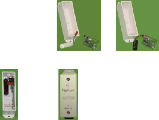
Figure 2-15 Figure 2-16
Figure 2-17 Figure 2-18
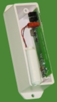
Battery Connection and Replacement The DigiGuard™ system uses a
custom lithium battery pack. The battery is rated for a minimum operational
life of ten years. The lithium battery ensures long life of the Door
Transmitter over wide temperature ranges. Using an alkaline or a non-
approved battery can damage the Door Transmitter and will void the
warranty. The battery is installed from the factory. The following instructions
are provided for installing as well as changing the battery. Always disarm
the system
before doing any work on the system.
Installing the Battery
1 Remove the screws from the Transmitter cover.
2 Remove the cover.
3 Plug the connector from the battery to the pins on the Transmitter board. Figure 2-14
4 Place the battery in the case above the top holding pin. Figure 2-17
5 Replace the cover and secure with the screws removed in Step 1. Figure 2-18

NOTE: Pay attention to the orientation of the battery connector. The battery will only connect
in one direction. Forcing the battery connector onto the pins can damage the Board. Also, pay
attention to the orientation of the cover with the case. Align the ridge on the top right of the
cover with the ridge on the case.
Putting the cover on backwards can damage the Transmitter Board.
Replacing the Battery
1 Remove the screws from the Transmitter cover.
2 Remove the cover.
3.Unplug the battery’s connector from the two pins on the Transmitter Board. Figure 2-15
1 Replace the old battery with the new Digitech replacement battery, connecting the plug on
the pins. Figure 2-16
2 Place the battery in the case above the top holding pin and mount with wires toward the
antenna. Figure 2-17
3 Replace the cover and secure with the screws removed in Step 1. Figure 2-18
This Page Left Blank Intentionally