RIFO TECHNOLOGY 02 WiFi Microcontroller Module User Manual Manual
RIFO TECHNOLOGY CO., LTD. WiFi Microcontroller Module Manual
Manual
____________________________________________________________________________________
WiFi Microcontroller Module
Model : WiFi Microcontroller Module
Part No : TC3200-S-ANT
Version : V1.1
Date : 2017.08.23
TC3200-S-ANT
2
■ Applications
■ Selection Guide
Denomination :WiFi Microcontroller Module
Part No. :TC3200-S-ANT (with Shielding case)
•
Internet of Things (IoT)
•
Cloud Connectivity
•
Home Automation
•
Home Appliances
•
Access Control
•
Security Systems
•
Smart Energy
• Internet Gateway
• Industrial Control
• Smart Plug and Metering
• Wireless Audio
• IP Network Sensor Nodes
• Wearables
TC3200-S-ANT
3
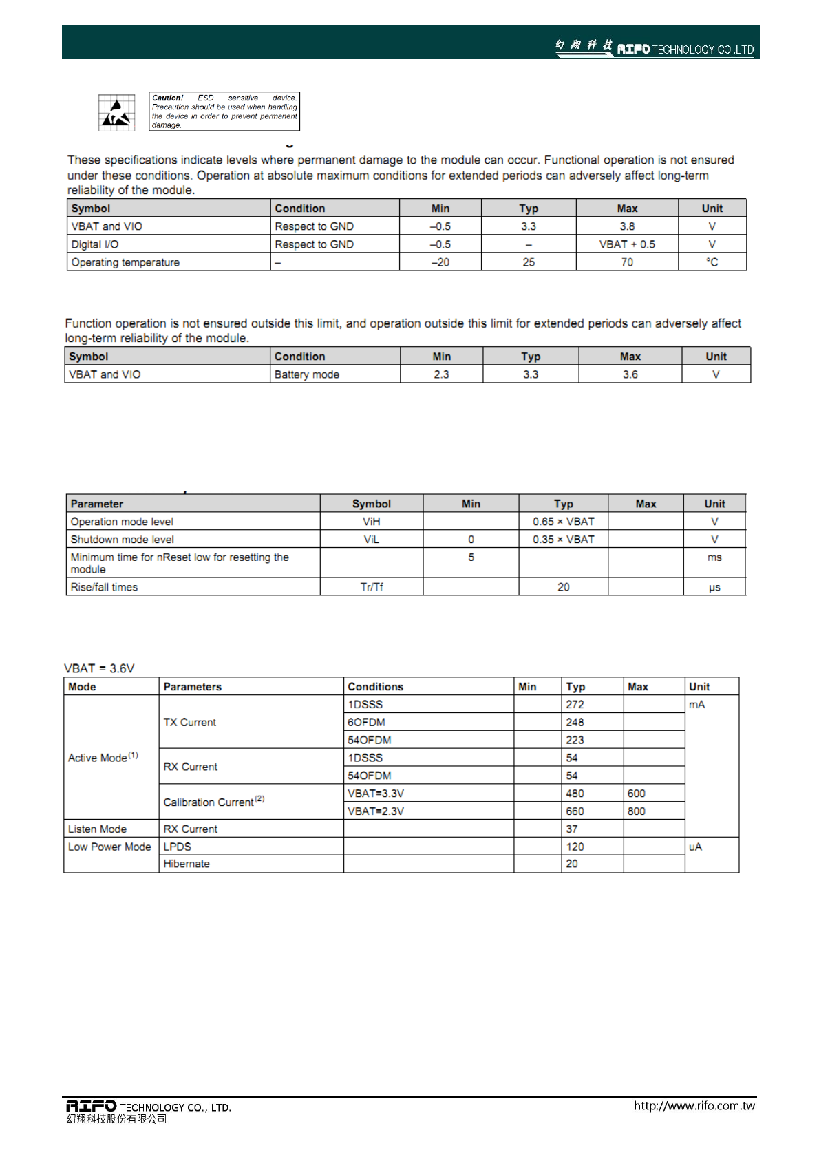
■ Absolute Maximum Ratings
■ Recommended Operation Condition
■ Electrical Specifications
RESET REQUIREMENT
CURRENT CONSUMPTION
TC3200-S-ANT
4
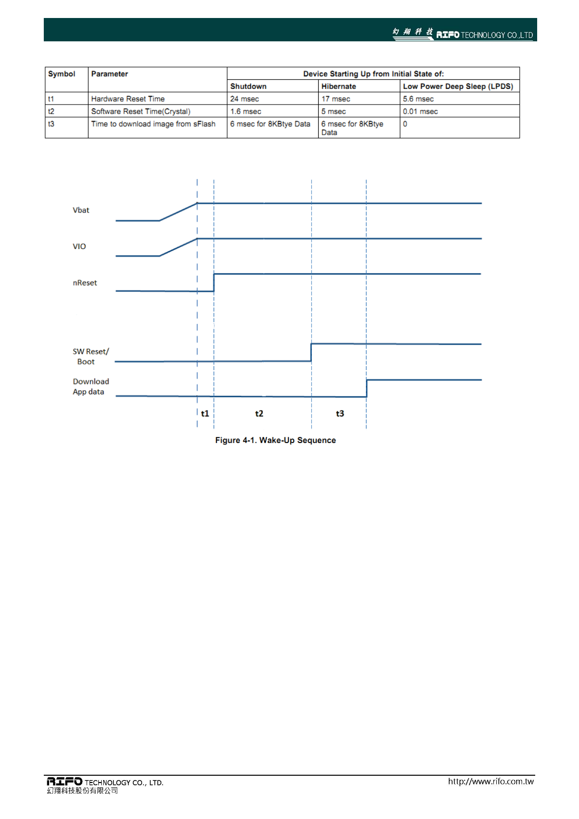
WAKEUP Sequence
TC3200-S-ANT
5
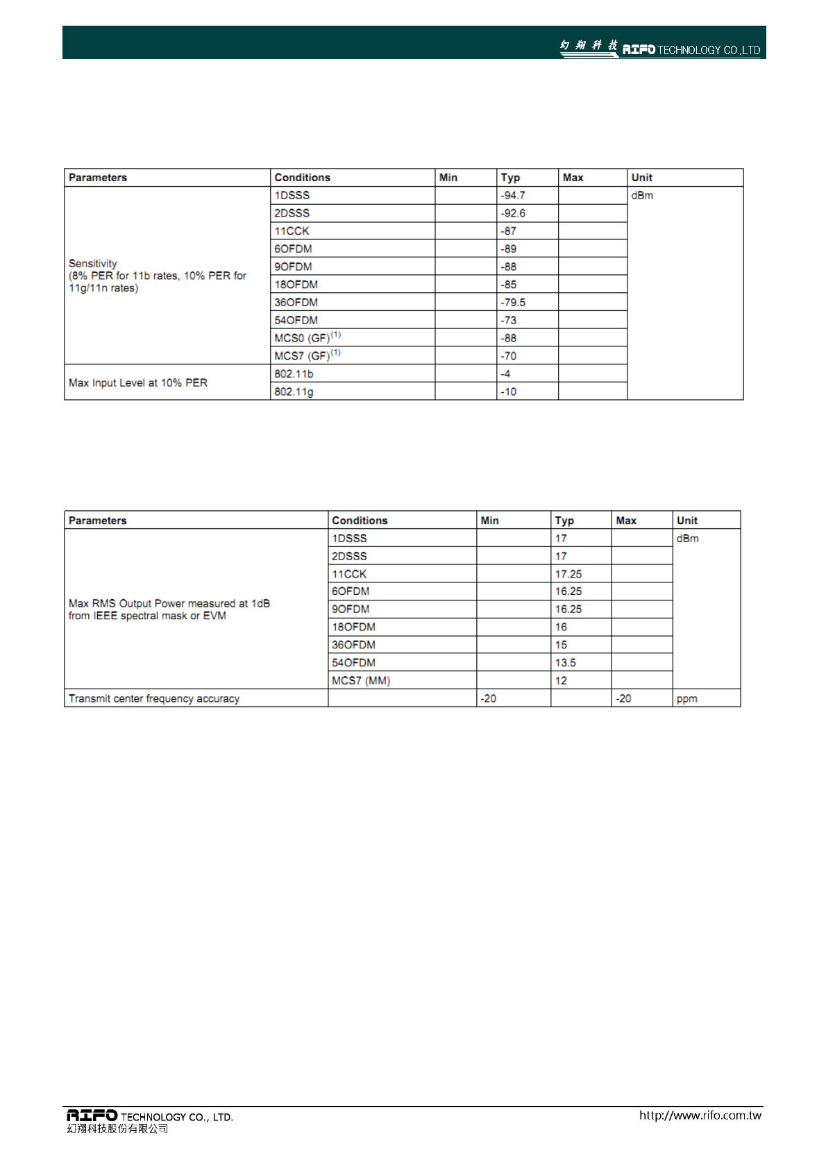
■ WLAN RF Characteristics
WLAN RECEIVER Characteristic
TA = 25°C and VDD = 3.3 V, unless otherwise noted.
WLAN TRANSMITTER Characteristic
TA = 25°C and VDD = 3.3 V, unless otherwise noted.
TC3200-S-ANT
6
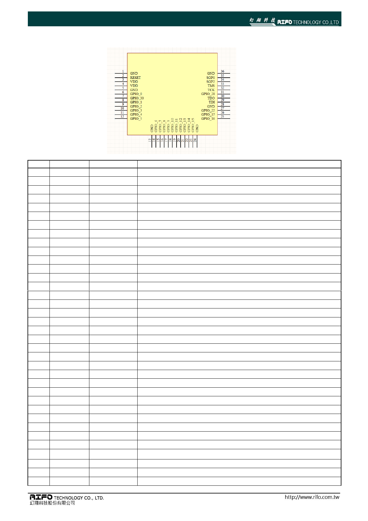
■ TC3200-S WiFi Module Pin Configuration
Pin #.
Pin Name
Pin Type
Description
1
GND
Ground
2
RESET
nRESET
Do not require external RC circuit
3
VDD
POWER
2.3~3.6V power supply
4
VDD
POWER
2.3~3.6V power supply
5
GND
Ground
6
GPIO_00
Digital I/O
7
GPIO_30
Digital I/O
8
GPIO_01
Digital I/O
9
GPIO_02
Digital I/O
10
GPIO_03
Digital I/O
11
GPIO_04
Digital I/O
12
GPIO_05
Digital I/O
13
GND
Ground
14
GPIO_06
Digital I/O
15
GPIO_07
Digital I/O
16
GPIO_08
Digital I/O
17
GPIO_09
Digital I/O
18
GPIO_10
Digital I/O
19
GPIO_11
Digital I/O
20
GPIO_12
Digital I/O
21
GPIO_13
Digital I/O
22
GPIO_14
Digital I/O
23
GPIO_15
Digital I/O
24
GND
Ground
25
GPIO_16
Digital I/O
26
GPIO_17
Digital I/O
27
GPIO_22
Digital I/O
28
GND
Ground
29
JTAG_TDI
Digital I/O
30
JTAG_TDO
Digital I/O
31
GPIO_28
Digital I/O
32
JTAG_TCK
Digital I/O
33
JTAG_TMS
Digital I/O
34
SOP2
Config I/O
Add option to pull up required for entering the UART load mode for flashing.
35
SOP0
Config I/O
Reserve(Do not use)
36
GND
GND
Ground
TC3200-S-ANT
7
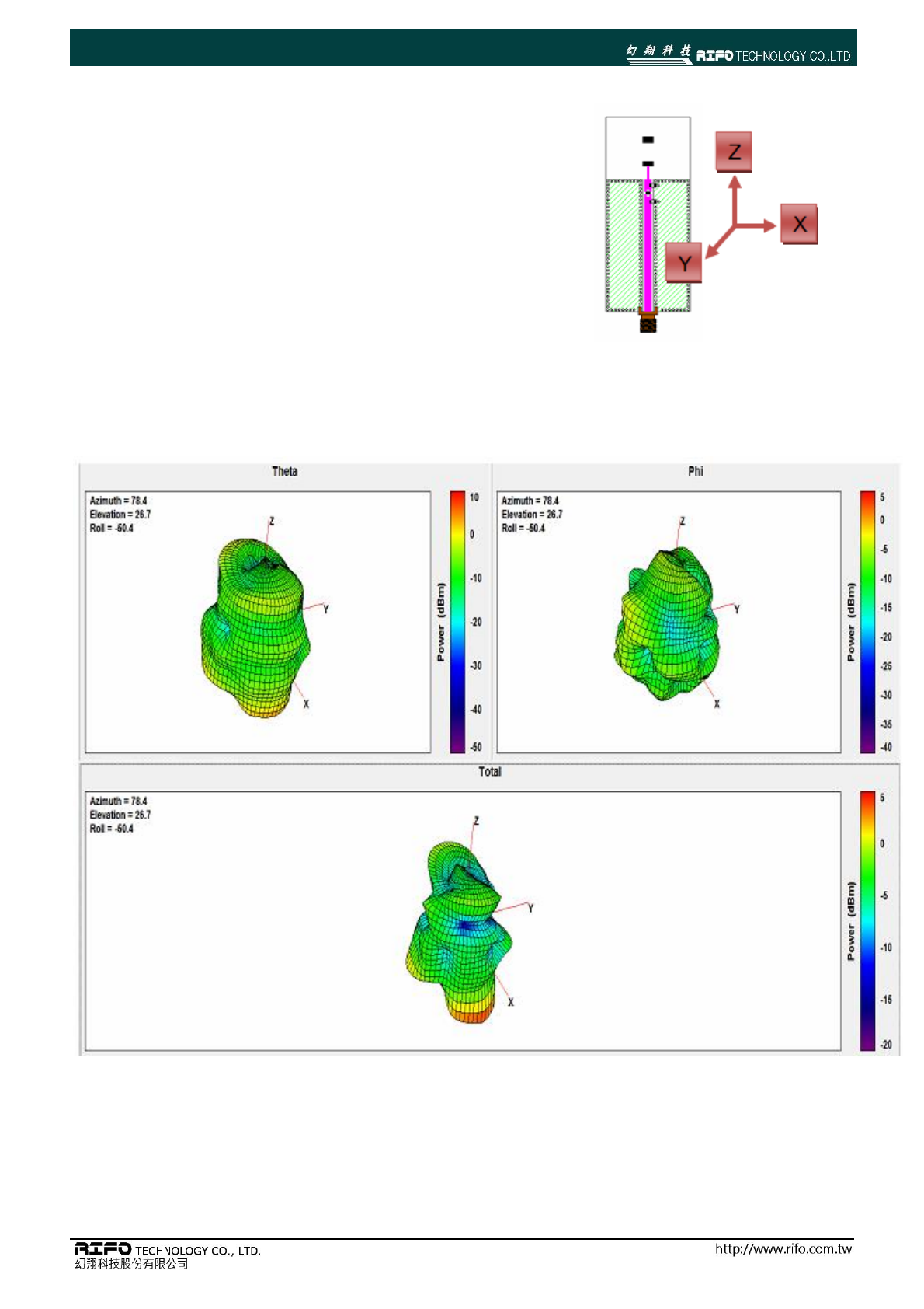
■ Antenna Radiation Pattern
TC3200-S-ANT
8
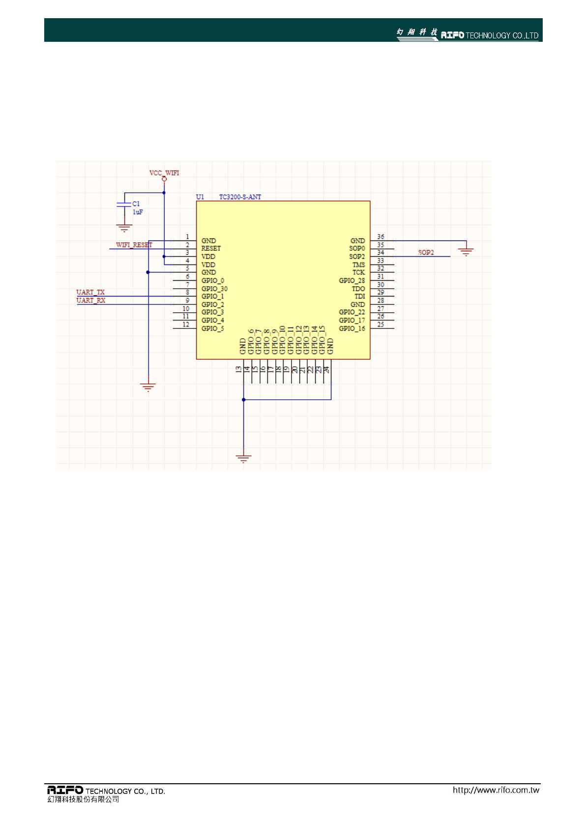
■ TC3200-S-ANT WiFi Module Example Design schematic
Example schematic:
TC3200-S-ANT
9
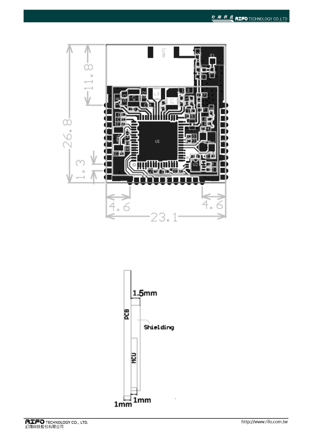
■ TC3200-S-ANT WIFI Module Dimension
TC3200-S-ANT
1
0
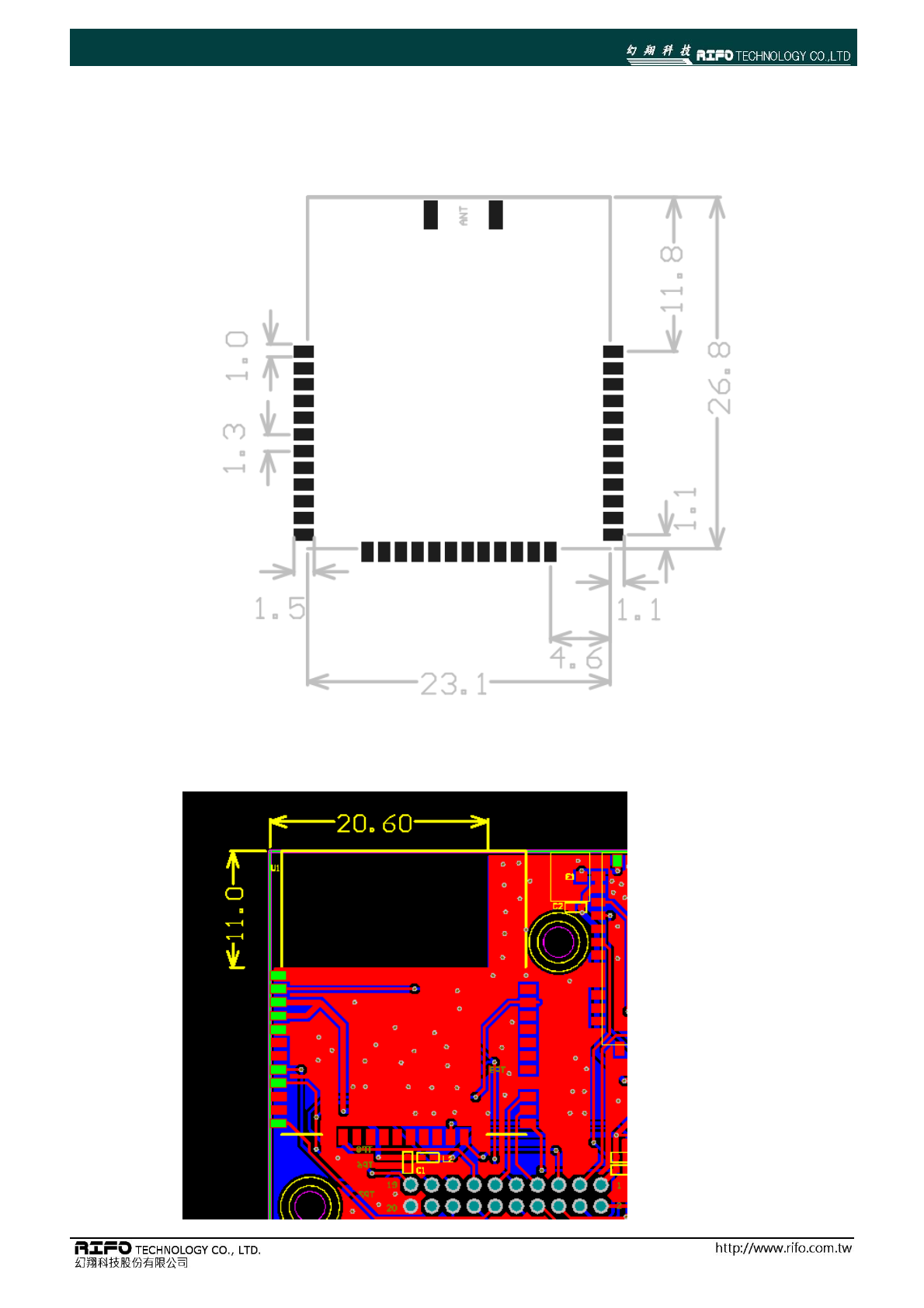
■ Recommended PCB layout for Module
■ Antenna Forbidden Area for PCB Layout

TC3200-S-ANT
1
1
■ FCC Statement:
This device complies with part 15 of the FCC Rules. Operation is subject to the following two conditions:
(1) This device may not cause harmful interference, and
(2) this device must accept any interference received, including interference that may cause undesired operation.
NOTE: This equipment has been tested and found to comply with the limits for a Class B digital device, pursuant to part 15
of the FCC Rules. These limits are designed to provide reasonable protection against harmful interference in a residential
installation.
This equipment generates, uses and can radiate radio frequency energy and, if not installed and used in accordance with
the instructions, may cause harmful interference to radio communications. However, there is no guarantee that
interference will not occur in a particular installation.
If this equipment does cause harmful interference to radio or television reception, which can be determined by turning the
equipment off and on, the user is encouraged to try to correct the interference by one or more of the following measures:
—Reorient or relocate the receiving antenna.
—Increase the separation between the equipment and receiver.
—Connect the equipment into an outlet on a circuit different from that to which the receiver is connected.
—Consult the dealer or an experienced radio/TV technician for help.
Changes or modifications not expressly approved by the party responsible for compliance could void the user’s authority
to operate the equipment.
The user manual of the final host must contain a statement similar to this:
This transmitter must be installed in a way that a separation distance of at least 20cm from all persons in normal use is
maintained.
■ Important FCC notice:
In accordance with FCC Part 15C, this module is listed as a Modular Transmitter device.
The antenna of this transmitter must not be co-located or operating in conjunction with any other antenna or
transmitters within a host device, except in accordance with FCC multitransmitter product approval procedures.
■ FCC Lable Instruction:
The outside of final products that contains this module device must display a label referring to the enclosed
module. This exterior label can use wording such as the following: Contains Transmitter Module FCC ID:
2AEQ402 or “Contains FCC ID:2AEQ402 Any similar wording that expresses the same meaning may be used.
▉ Taiwan requlatory information(NCC)
低功率電波輻射性電機管理辦法
TC3200-S-ANT
1
2
第十二條 經型式認證合格之低功率射頻電機,非經許可,公司、商號或使用者均不得擅自變
更頻率、加大功率或變更原設計之特性及功能。
第十四條 低功率射頻電機之使用不得影響飛航安全及干擾合法通信;經發現有干擾現象時,
應立即停用,並改善至無干擾時方得繼續使用。
前項合法通信,指依電信法規定作業之無線電通信。
低功率射頻電機須忍受合法通信或工業、科學及醫療用電波輻射性電機設備之干擾。
■ Document History
Revision
Date
Description/Changes
1.0
2016.11.16
First release
1.1
2017.08.23
ADD FCC/NCC statement
■ Address Information

TC3200-S-ANT
1
3