RINNAI AMERICA Furnace Wall Manual L0408132
User Manual: RINNAI RINNAI AMERICA Furnace Wall Manual RINNAI AMERICA Furnace Wall Owner's Manual, RINNAI AMERICA Furnace Wall installation guides
Open the PDF directly: View PDF ![]() .
.
Page Count: 60
HOME OWNER /INSTALLER
FOR YOUR SAFETY
THIS MANUAL MUST BE READ IN ITS
ENTIRETY BEFORE OPERATING HEATER
RHFE-1004FA
ENERGYSAVER
GAS DIRECT VENT WALL FURNACE
Owner's Operation and Installation Manual
WARNING: IF THE INFORMATION IN THIS MANUAL iS NOT FOLLOWED
EXACTLY, A FIRE OR EXPLOSION MAY RESULT CAUSING PROPERTY
DAMAGE, PERSONAL INJURY OR LOSS OF LIFE.
DO NOT STORE OR USE GASOLINE OR OTHER FLAMMABLE VAPORS
AND LIQUIDS IN THE VICINITY OF THIS OR ANY OTHER APPLIANCE.
WHAT TO DO IF YOU SMELL GAS
•DO NOT TRY TO LIGHT ANY APPLIANCE.
• DO NOT TOUCH ANY ELECTRICAL SWITCH; DO NOT USE ANY PHONE
IN YOUR BUILDING.
•IMMEDIATELY CALL YOUR GAS SUPPLIER FROM ANEIGHBOR'S
PHONE. FOLLOW THE GAS SUPPLIER'S INSTRUCTIONS.
• IF YOU CANNOT REACH YOUR GAS SUPPLIER, CALL THE FIRE
DEPARTMENT.
INSTALLATION AND SERVICE MUST BE PERFORMED BY A QUALIFIED
INSTALLER, SERVICE AGENCY OR THE GAS SUPPLIER.
IThis appliance may be installed in a after market permanently located,
manufactured (mobile) home, where not prohibited by local codes. |
This appliance is only for use with the type of gas indicated on the Rating Plate. /
isThiLSs:;plianceis not convertible for use with other gases, unless a certified kit J
INSTALLER: MUST LEAVE MANUAL WITH UNIT AFTER INSTALLATION.
OWNER: RETAIN THIS MANUAL SAFELY, FOR FUTURE REFERENCE.
rWARNING
IMPROPER INSTALLATION, ADJUSTMENT, ALTERATION,
SERVICE OR MAINTENANCE CAN CAUSE PROPERTY
DAMAGE, PERSONAL INJURY OR LOSS OF LIFE, REFER
TO THE OWNER'S INFORMATION MANUAL PROVIDED
WITH THIS APPLIANCE. INSTALLATION AND SERVICE
MUST BE PERFORMED BY A QUALIFIED INSTALLER,
SERVICE AGENCY OR THE GAS SUPPLIER.
.. j
ENERGYSAVER RHFE-1004FA
Operation Manual
Table of Contents
Page
FEATURES OF THE RHFE-1004FA UNITS ....................... ................................... 1
SAFETY DEVICES ................................................................................................ 1
IMPORTANT POINTS /USAGE AND INSTALLATION MUSTS ............................ 3
DIMENSIONS ........................................................................................................ 5
SPECIFICATIONS ................................................................................................. 6
SAFETY POINTS .................................................................................................. 8
GETTING TO KNOW YOUR NEW RHFE-1004FA ................................................ 10
CONTROL PANEL ................................................................................................. 11
CUT-AWAY DIAGRAM ........................................................................................... 12
NOTICE BEFORE INSTALLATION ........................................................................ 13
INSTALLATION INSTRUCTIONS .......................................................................... 14
GAS CONNECTION .............................................................................................. 15
CANADIAN VENT REGULATIONS ....................................................................... 16
LOCATION /CLEARANCES .................................................................................. 17
SLEEVE AND MANIFOLD INSTALLATION ........................................................... 19
FI'I-I'ING UNIT ....................................................................................................... 21
OPERATING INSTRUCTION LABEL .................................................................... 23
ADDITIONAL CUSTOMER OPERATING INFORMATION .................................... 24
TESTING ............................................................................................................... 30
CHECK .................................................................................................................. 30
PRE-SERVICE CHECK ......................................................................................... 31
TROUBLE SHOOTING .......................................................................................... 32
ERROR MESSAGES .............................................................................................. 33
MAINTENANCE /SERVICE .................................................................................. 34
WIRING DIAGRAM ................................................................................................ 35
WARRANTY INFORMATION ................................................................................. 36
SCHEMATIC DIAGRAM ........................................................................................ 38
PARTS LIST ........................................................................................................... 45
RHFE-1004FA FLOW DIAGRAM ........................................................................... 50
EXTENDED FLUE PIPE KIT ................................................................................. 51
TECHNICAL DATA ................................................................................................. 56
IFEATURES OF THE RHFE-1004FA UNITS
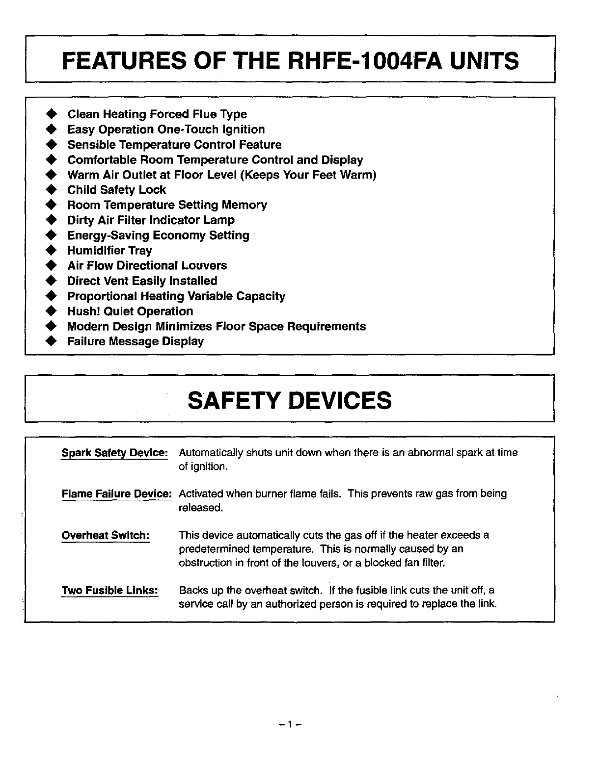
•Clean Heating Forced Flue Type
•Easy Operation One-Touch Ignition
•Sensible Temperature Control Feature
•Comfortable Room Temperature Control and Display
•Warm Air Outlet at Floor Level (Keeps Your Feet Warm)
•Child Safety Lock
•Room Temperature Setting Memory
•Dirty Air Filter Indicator Lamp
•Energy-Saving Economy Setting
•Humidifier Tray
•Air Flow Directional Louvers
•Direct Vent Easily Installed
•Proportional Heating Variable Capacity
•Hush! Quiet Operation
•Modern Design Minimizes Floor Space Requirements
•Failure Message Display
ISAFETY DEVICES I
Spark Safety Device: Automatically shuts unit down when there is an abnormal spark at time
of ignition.
Flame Failure Device: Activated when burner flame fails. This prevents raw gas from being
released.
Overheat Switch: This device automatically cuts the gas off if the heater exceeds a
predetermined temperature. This is normally caused by an
obstruction in front of the louvers, or a blocked fan filter,
Two Fusible Links: Backs up the overheat switch. If the fusible link cuts the unit off, a
service call by an authorized person is required to replace the link.
-1-
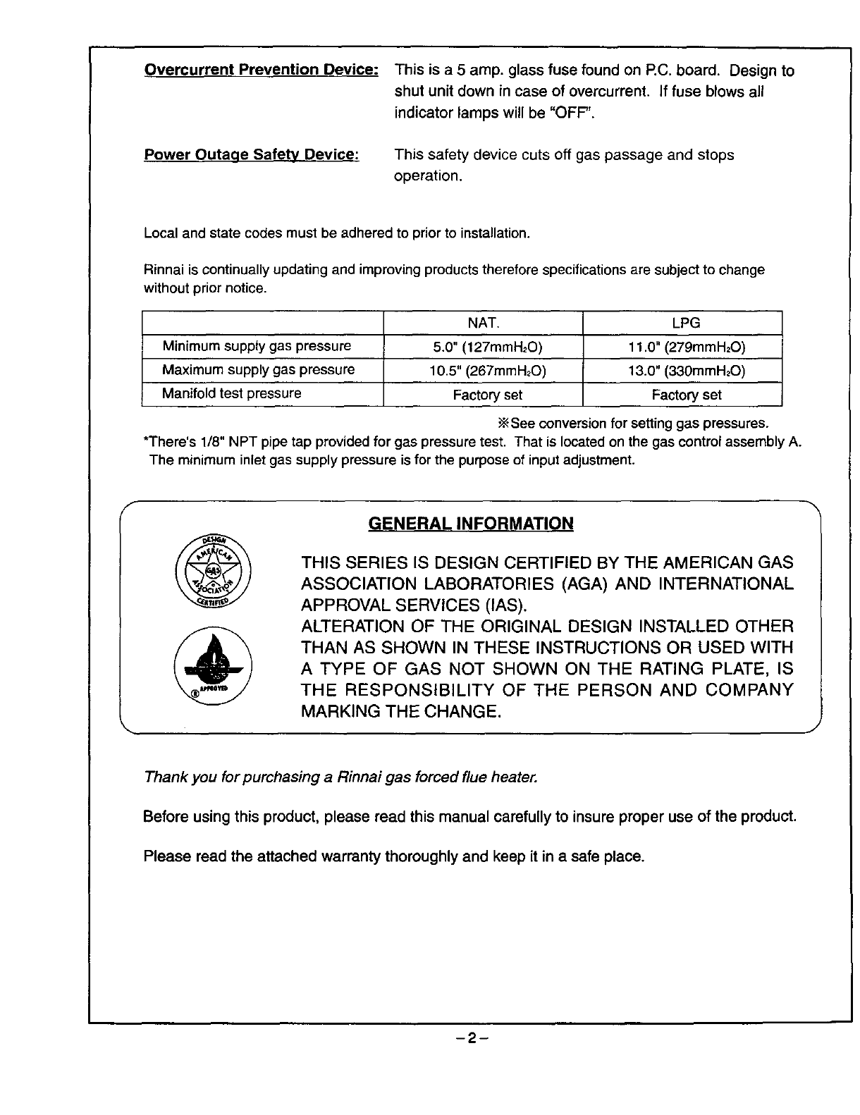
Overcurrent Prevention Device:
Power Outaqe Safety Device:
This is a 5 amp. glass fuse found on P.C. board. Design to
shut unit down in case of overcurrent. If fuse blows all
indicator lamps will be "OFF".
This safety device cuts off gas passage and stops
operation.
Local and state codes must be adhered to prior to installation.
Rinnai is continually updating and improving products therefore specifications are subject to change
without prior notice.
NAT, LPG
Minimum supply gas pressure 5.0" (127mmH20) 11.0" (279mmH20)
Maximum supply gas pressure 10.5" (267mmH20) 13.0" (330mmH20)
Manifold test pressure Factory set Factory set
•_See conversion for setting gas pressures.
•There's 1/8" NPT pipe tap provided for gas pressure test. That is located on the gas control assembly A.
The minimum inlet gas supply pressure is for the purpose of input adjustment.
f
GENERAL INFORMATION
THIS SERIES IS DESIGN CERTIFIED BY THE AMERICAN GAS
ASSOCIATION LABORATORIES (AGA) AND INTERNATIONAL
APPROVAL SERVICES (IAS).
ALTERATION OF THE ORIGINAL DESIGN INSTALLED OTHER
THAN AS SHOWN IN THESE INSTRUCTIONS OR USED WITH
A TYPE OF GAS NOT SHOWN ON THE RATING PLATE, IS
THE RESPONSIBILITY OF THE PERSON AND COMPANY
MARKING THE CHANGE.
Thank you for purchasing a Rinnai gas forced flue heater.
Before using this product, please read this manual carefully to insure proper use of the product.
Please read the attached warranty thoroughly and keep it in a safe place.
-2-
IMPORTANTPOINTS/USAGEANDINSTALLATIONMUSTS
Unpack heater and check for damage. (DO NOT INSTALL DAMAGED HEATER.) If heater is
damaged, contact your supplier for advice. Before installing a heater, check the label for the correct gas
type (see label on heater). Refer to local gas authority for confirmation of gas type if you are in doubt.
Included in Carton:
Customers Operating Information
IMPORTANT
Before using this product, please read this manual carefully to insure proper use of product.
1. The installation must conform with local codes or, in absence of local codes, the National Fuel Gas
Code, ANSI Z223.1 or the Canadian Installation Code, CAN/CGA-B149.
2. For information on gas type, see data plate on the appliance.
3. This heater must not be installed where curtains or other combustible materials could come into
contact with it. In some cases curtains may need restraining.
4. This appliance is not designed to be built in.
5. If you move, check the gas type in the area where you are moving to. The local gas authority will be
able to advise on local regulations.
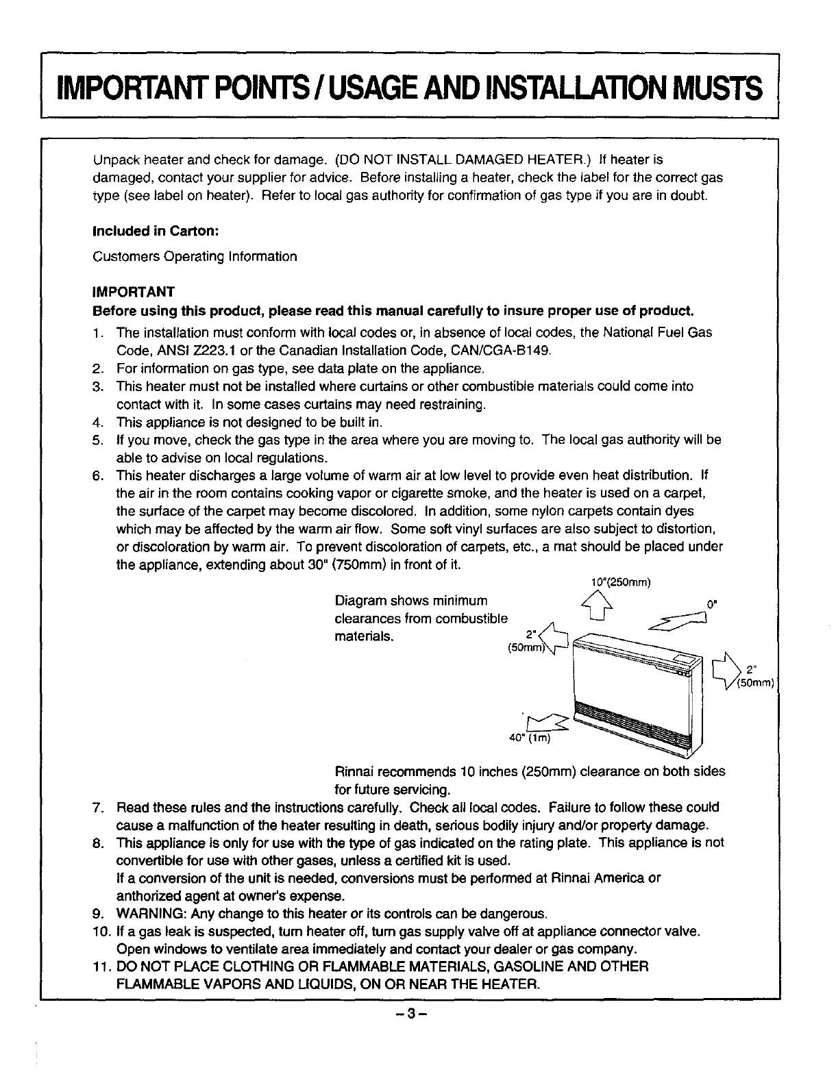
6. This heater discharges a large volume of warm air at low level to provide even heat distribution. If
the air in the room contains cooking vapor or cigarette smoke, and the heater is used on a carpet,
the surface of the carpet may become discolored. In addition, some nylon carpets contain dyes
which may be affected by the warm air flow. Some soft vinyl surfaces are also subject to distortion,
or discoloration by warm air. To prevent discoloration of carpets, etc., a mat should be placed under
the appliance, extending about 30" (750mm) in front of it.
10"(250ram)
Diagram shows minimum _/"_ o"
clearances from combustible L._J
materials. 2%
40" (lm)
Rinnai recommends 10 inches (250mm) clearance on both sides
for future servicing.
7. Read these rules and the instructions carefully. Check all local codes. Failure to follow these could
cause a malfunction of the heater resulting in death, serious bodily injury and/or property damage.
8. This appliance is only for use with the type of gas indicated on the rating plate. This appliance is not
convertible for use with other gases, unless acertifiedkit is used.
If a conversion of the unit is needed, conversions must be performed at Rinnai America or
anthorized agent at owner's expense.
9. WARNING: Any change to this heater or its controls can be dangerous.
10. if a gas leak is suspected, turn heater off, tum gas supply valve off at appliance connector valve.
Open windows to ventilate area immediately and contact your dealer or gas company.
11. DO NOT PLACE CLOTHING OR FLAMMABLE MATERIALS, GASOLINE AND OTHER
FLAMMABLE VAPORS AND LIQUIDS, ON OR NEAR THE HEATER.
-3-

12. YOUNG CHILDREN SHOULD BE CAREFULLY SUPERVISED WHEN THEY ARE IN THE SAME
ROOM WITH THE HEATER.
13. LPG containers must not be installed indoors.
14. Do not Use this room heater if any part has been under water. Immediately call a qualified service
technician to inspect the room heater and to replace any part of the control system and any gas
control which has been under water.
15. Adequate clearances for accessibility for purposes of servicing and proper operation should be
provided.
16. Adequate clearances around air openings should be provided.
17. Do not install in areas where curtains, drapes, clothing, or other moving flammables are within 12
inches of this unit.
18. Periodic examination of the venting system is required.
19. The flow of combustion and ventilation air should not be obstructed.
20. A manufactured Home (Mobile Home) installation must conform with the Manufactured Home
Construction and Safety Standard, title 24CFR, Part 3280, or, when such a standard is not
applicable, the Standard for Manufactured Home Installations, ANSI A225.1 or Standard for Gas
Equipped Recreational Vehicles and Mobile Housing, CSA Z240.4.
21. "This appliance must be installed in accordance with the current standard CSA Z2.40.4 GAS
EQUIPPED RECREATIONAL VEHICLES AND MOBILE HOUSING. Cet appareil dolt ette installe
conformement aux, exigences de la norme Z240.4 en vigeuer de rACNOR, Installations de gaz dans
les constructions mobiles et vehicules recreatifs."
22. If a blockage occurs at the vent terminal due to snow, ice, leaves, spider webs or other type of
obstructions the unit will stop working. The unit will not function until the blockage has been
removed. If the unit then fails to operate contact a qualified service agency.
23. For manufactured (mobile) home or residential installation, this unit has been designed and certified
to be converted from natural gas to propane or vice-versa. When provisions are being made to
convert this unit, a certified conversion kit must be used. You must also readjust manifold gas
pressure to specifications indicated in the conversion manual. If in doubt contact Rinnai America for
assistance.
24. Clothing or other flammable material should not be placed on or near the appliance.
-4-
DIMENSIONS
inches (ram)
p
I
_: 14 1/16" (357.5)
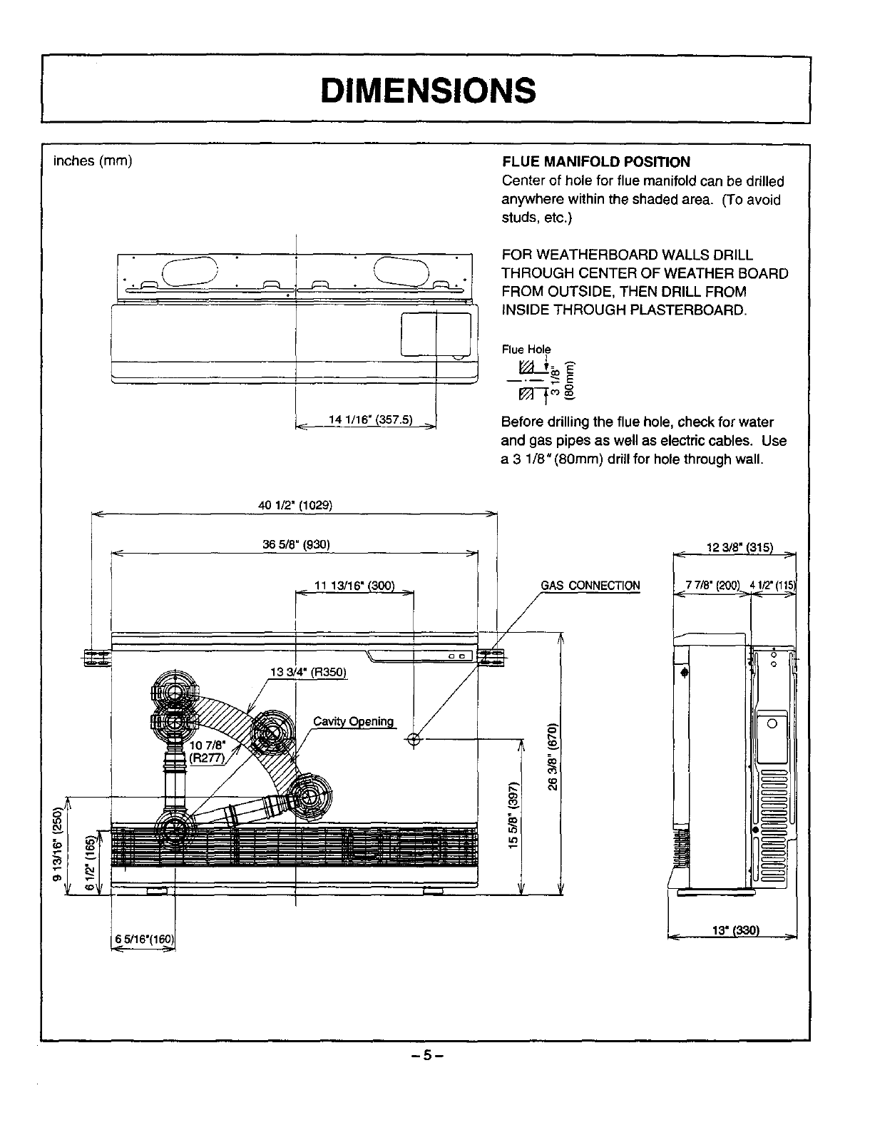
FLUE MANIFOLD POSITION
Center of hole for flue manifold can be drilled
anywhere within the shaded area. (To avoid
studs, etc.)
FOR WEATHERBOARD WALLS DRILL
THROUGH CENTER OF WEATHER BOARD
FROM OUTSIDE, THEN DRILL FROM
INSIDE THROUGH PLASTERBOARD.
Flue Hole
-----_E g
Before drilling the flue hole, check for water
and gas pipes as well as electric cables. Use
a 3 1/8" (80ram) drill for hole through wall.
40 1/2" (1029)
365/8"(93o)
< 11 13/16" (300)
I
13 3/4" q
GAS CONNECTION
12 3/8"_
-5-
ISPECIFICATIONS
MODEL #
RHFE-1004FA-N
NATURAL
RHFE-1004FA-P
PROPANE
BTU/h
INPUT OUTPUT
Low Low
10,500 8,400
High High
38,400 30,700
Low Low
10,500 8,400
High High
36,500 29,200
MIN. CLEARANCES
SIDE
2 H
(50mm)
2 n
(50mm)
TOP FRONT
10" 40"
(250mm) (lm)
10" 40"
(250ram) (lm)
FAN CFM
OUTPUT
LO:203.4
H1:360.6
LO:203.4
H1:360.5
SPECIFICATIONS
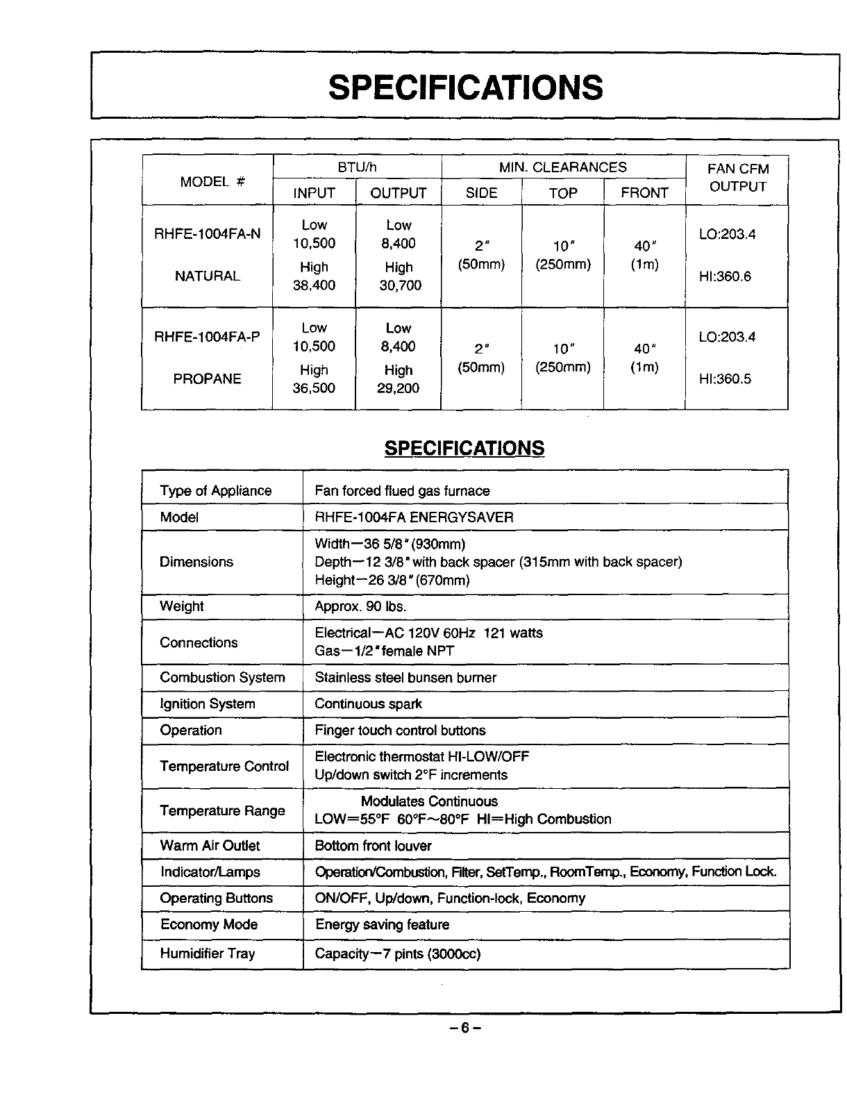
Type of Appliance Fan forced flued gas furnace
Model RHFE-1004FA ENERGYSAVER
Width--36 5/8" (930mm)
Dimensions Depth--12 3/8" with back spacer (315mm with back spacer)
Height--26 3/8" (670mm)
Weight Approx. 90 Ibs.
ElectricaI--AC 120V 60Hz 121 watts
Connections Gas--l/2" female NPT
Combustion System Stainless steel bunsen burner
Ignition System Continuous spark
Operation Finger touch control buttons
Electronic thermostat HI-LOW/OFF
Temperature Control Up/down switch 2°F increments
Modulates Continuous
Temperature Range LOW----55°F 60°F_80°F HI=High Combustion
Warm Air Outlet Bottom front louver
Indicator/Lamps Operation/Combustion,Filter,SetTemp., RcomTemp., Economy,FunctionLock.
Operating Buttons ON/OFF, Up/down, Function-lock, Economy
Economy Mode Energy saving feature
Humidifier Tray Capacity--7 pints (3000cc)
-6-
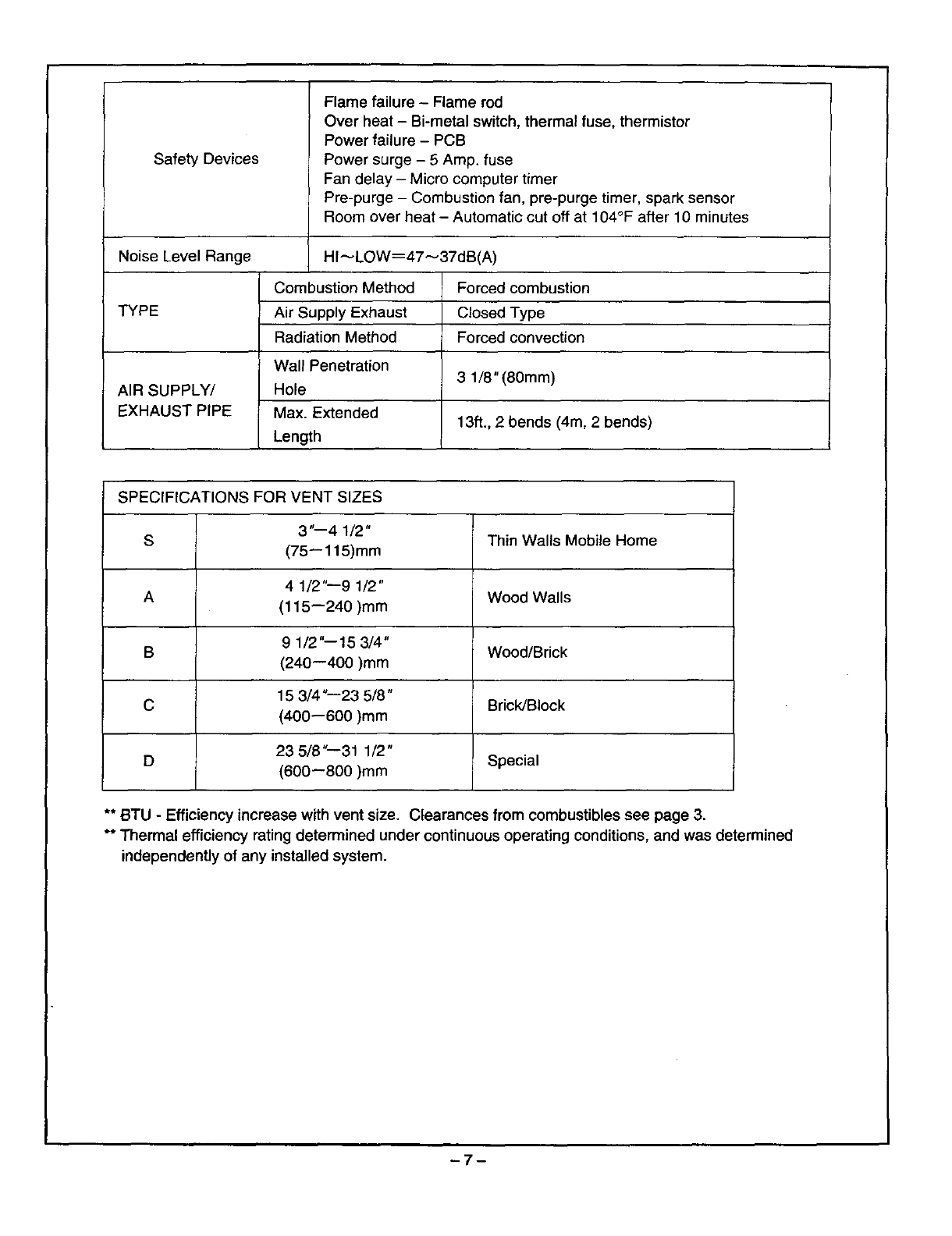
Safety Devices
Flame failure - Flame rod
Over heat -Bi-metal switch, thermal fuse, thermistor
Power failure - PCB
Power surge -5 Amp. fuse
Fan delay - Micro computer timer
Pre-purge - Combustion fan, pre-purge timer, spark sensor
Room over heat -Automatic cut off at 104°F after 10 minutes
Noise Level Range HI_LOW----47_37dB(A)
Combustion Method Forced combustion
TYPE Air Supply Exhaust Closed Type
Radiation Method Forced convection
Wall Penetration 3 1/8" (80mm)
AIR SUPPLY/ Hole
EXHAUST PIPE Max. Extended 13ft., 2 bends (4m, 2 bends)
Length
SPECIFICATIONS FOR VENT SIZES
3"--4 1/2"
S Thin Walls Mobile Home
(75--115)mm
4 1/2"--9 1/2"
A Wood Walls
(115--240)mm
9 1/2"--15 3/4"
B Wood/Brick
(240--400)mm
15 3/4 "--23 5/8"
C Brick/Block
(400--600)mm
23 5/8"--31 1/2"
D Special
(600--800)mm
** BTU - Efficiency increase with vent size. Clearances from combustibles see page 3.
** Thermal efficiency rating determined under continuous operating conditions, and was determined
independently of any installed system.
-7-
I SAFETY POINTS
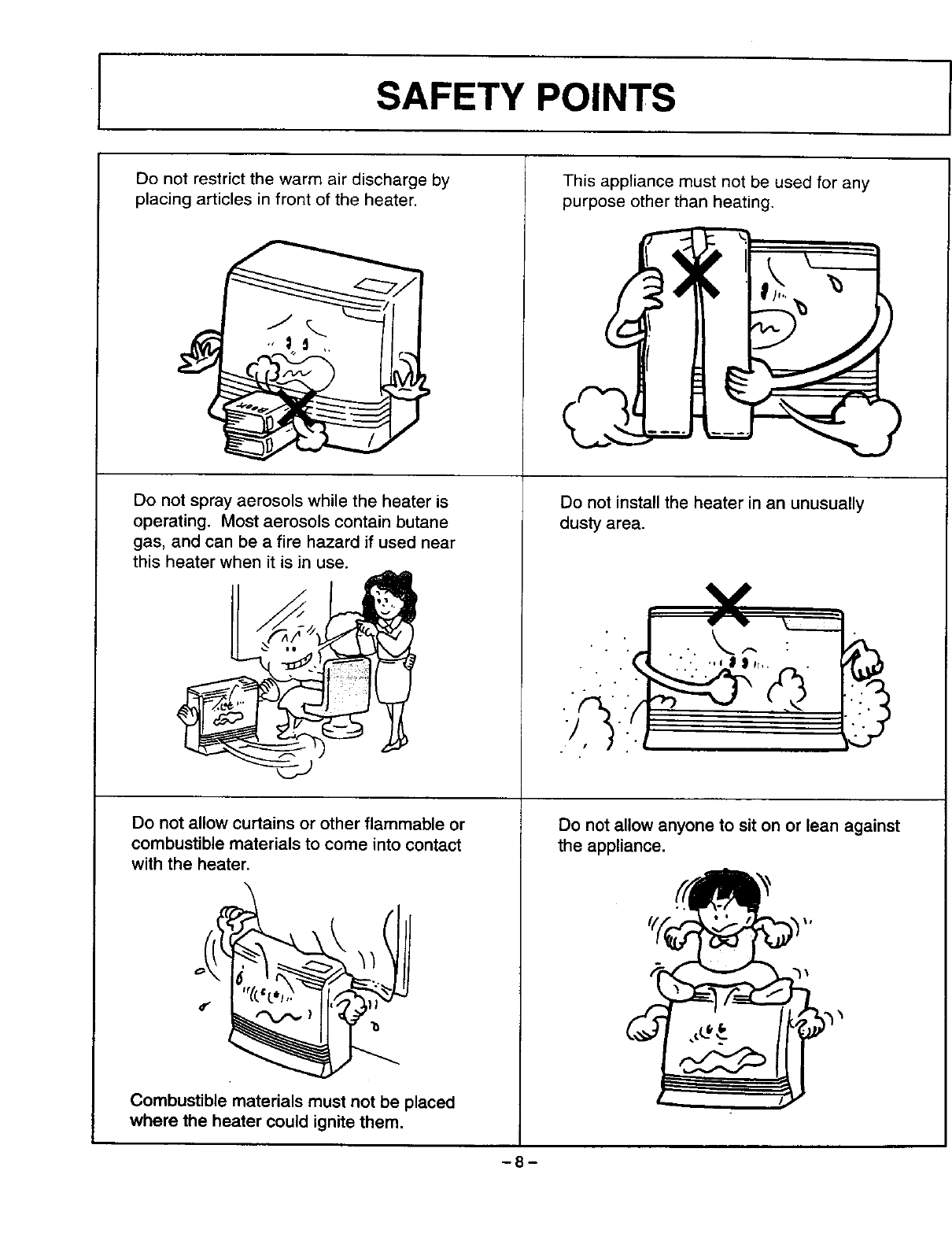
Do not restrict the warm air discharge by
placing articles in front of the heater.
Do not spray aerosols while the heater is
operating. Most aerosols contain butane
gas, and can be a fire hazard if used near
this heater when it is in use.
Do not allow curtains or other flammable or
combustible materials to come into contact
with the heater.
Combustible materials must not be placed
where the heater could ignite them.
This appliance must not be used for any
purpose other than heating.
Do not install the heater in an unusually
dusty area.
•Y
Do not allow anyone to sit on or lean against
the appliance.
-8-
SAFETY POINTS J
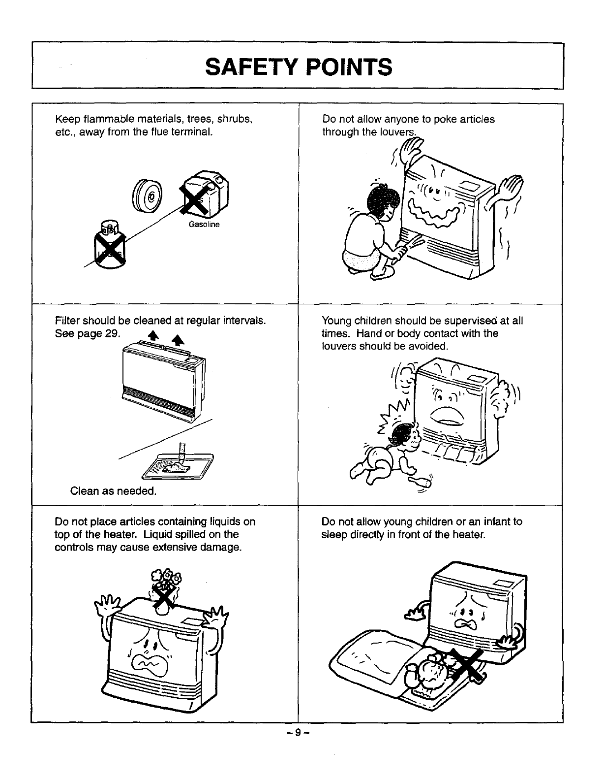
Keep flammable materials, trees, shrubs,
etc., away from the flue terminal.
Gasoline
Do not allow anyone to poke articles
through the louvers.
Filter should be cleaned at regular intervals.
See page 29.
Young children should be supervised at all
times. Hand or body contact with the
Clean as needed.
Do not place articles containing liquids on
top of the heater. Liquid spilled on the
controls may cause extensive damage.
louvers should be avoided.
Do not allow young children or an infant to
sleep directly in front of the heater.
-9-
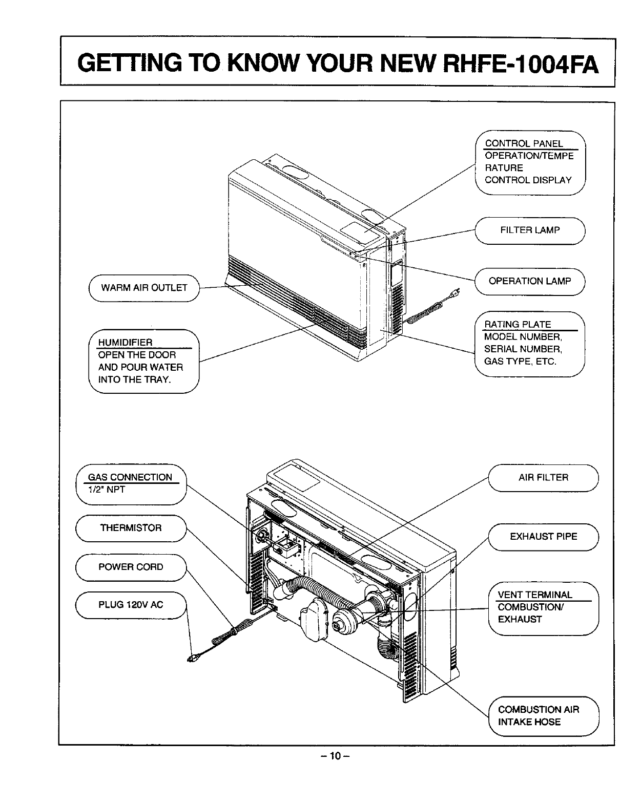
I GE'rrlNG TO KNOW YOUR NEW RHFE-1004FA I
CONTROL PANEL
_P_l
RATURE |
CONTROL DISPLAY J
FILTER LAMP
WARMA,ROUTLET_ _ OPERATIONLAMP
_HUMIDIFIER
I_OOR
|AND POUR WATER
_,/NTO THE TRAY.
1/2" NPT
THERMISTOR
POWER CORD
PLUG 120V AC
RATING PLATE 1
MODEL NUMBER,
SERIAL NUMBER,
GAS TYPE, ETC.
AIR FILTER
EXHAUST PIPE
VENT TERMINAL
COMBUSTION/
EXHAUST
COMBUSTION AIR
INTAKE HOSE
-10-
CONTROL PANEL
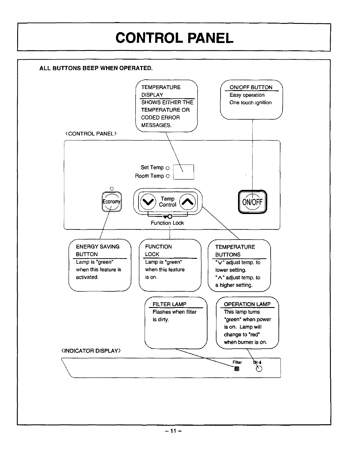
ALL BunONS BEEP WHEN OPERATED.
(CONTROLPANEL>
f
TEMPERATURE
DISPLAY
SHOWS EITHER THE
TEMPERATURE OR
CODED ERROR
MESSAGES. J
\
R¢_e_ TT:_ __
ON/OFF SUTTON 1
Easy operation
One touch ignition
©
ENERGY SAVING
BUTTON
Lampis "green"
whenthisfeature is
activated.
Temp
Control
Function Lock
[
I
fFUNCTION
LOCK
Lamp is "green"
when this feature
JS on. TEMPERATURE 1
BUTTONS
"v" adjust temp. to
lower setting.
"A" adjust temp. to
__a higher setting,
J
<INDICATOR DISPLAY)
\
fFILTER LAMP
Flashes when filter
is dirty.
OPERATION LAMP
This lamp tums
"green" when power
is on. Lamp will
change to "red"
when burner is on.
JJ
-11 -
I
I
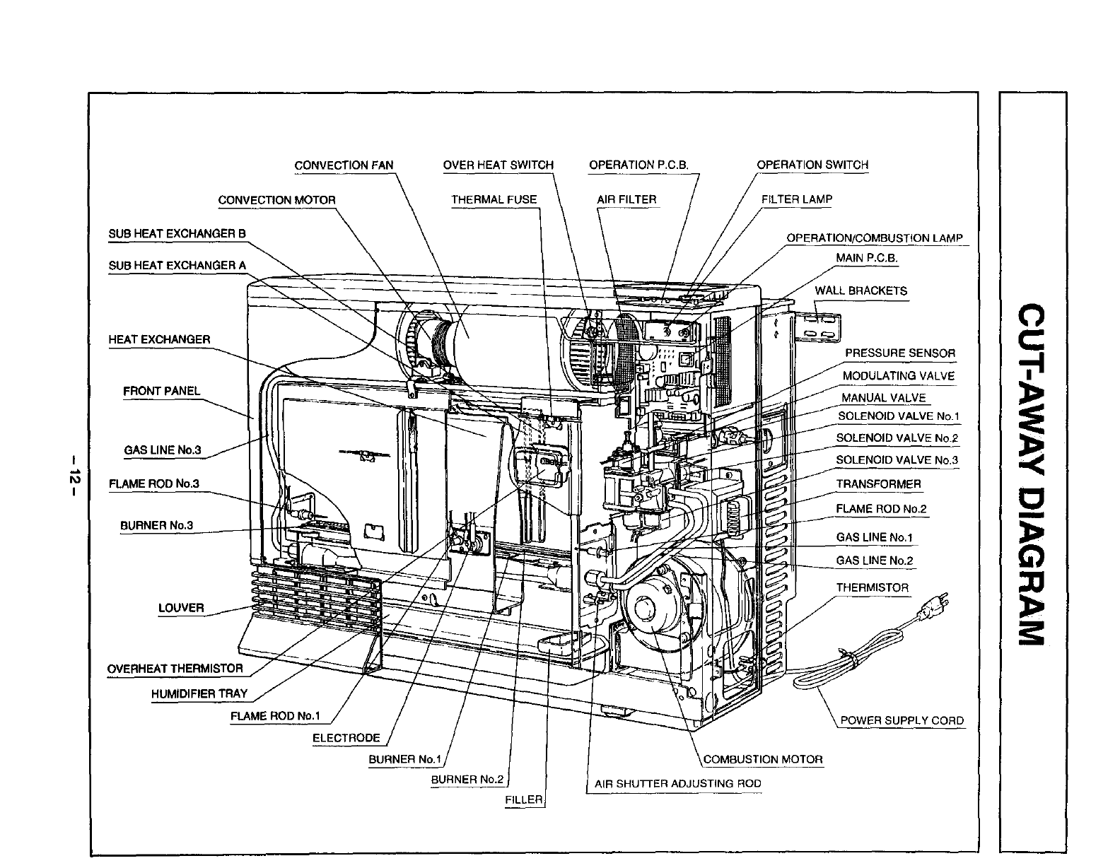
CONVECTION FAN
CONVECTION MOTOR
SUB HEAT EXCHANGER B
SUB HEAT EXCHANGER A
OVER HEAT SWITCH
THERMAL FUSE
HEAT EXCHANGER
FRONT PANEL
GAS LINE No.3
FLAME ROD No.3
BURNER No.3
LOUVER
OVERHEAT THERMISTOR
HUMIDIFIER TRAY
FLAME ROD NO.1
ELECTRODE
BURNER NO.1
BURNER No.2
FILLER
OPERATION P.C.B.
AIR FILTER
OPERATION SWITCH
FILTER LAMP
OPERATION/COMBUSTION LAMP
MAIN P.C.B.
WALL BRACKETS
PRESSURE SENSOR
MODULATING VALVE
MANUAL VALVE
SOLENOID VALVE NO.1
SOLENOID VALVE NO.2
SOLENOID VALVE NO.3
TRANSFORMER
FLAME ROD NO.2
GAS LINE No.1
GAS LINE No.2
THERMISTOR
POWER SUPPLY CORD
_COMRUSTION MOTOR
AIR SHUT[ER ADJUSTING ROD
O
,-i
I
INOTICE BEFORE INSTALLATION
The heater must be installed by a qualified service
person according to these installation instruction.
Check your local building codes for the proper method
of installation. In the case of absence of local cedes,
this heater should be ir_stalled in accordance with the
National Fuel Gas Code ANSI 7_223.1.
Check local codes or, in the absence of local codes,
the current CAN/CGA B149 INSTALLATION CODE.
DUE TO HIGH TEMPERATURES, THE
APPLIANCE SHOULD BE LOCATED OUT OF
TRAFFIC AND AWAY FROM FURNITURE AND
DRAPERIES.
CHILDREN AND ADULTS SHOULD BE ALERTED
TO THE HAZARDS OF HIGH SURFACE
TEMPERATURES AND SHOULD STAY AWAY TO
AVOID BURNS OR CLOTHING IGNITION.
"WARNING" Do not operate appliance with the
panel(s) removed, cracked or broken. Replacement
of the panel(s) should be clone by alicensed or
qualified service person.
INSTALLATION AND REPAIR SHOULD BE DONE
BY A QUALIFIED SERVICE PERSON. THE
APPLIANCE SHOULD BE INSPECTED BEFORE
USE AND AT LEAST ANNUALLY BY A QUALIFIED
SERVICE PERSON. MORE FREQUENT
CLEANING MAY BE REQUIRED DUE TO
EXCESSIVE LINT FROM CARPETING, BEDDING
MATERIAL, ETC. IT IS IMPERATIVE THAT
CONTROL COMPARTMENTS, BURNERS AND
CIRCULATING AIR PASSAGEWAYS OF THE UNIT
BE KEPT CLEAN.
The appliance, when installed, must be electrically
grounded in accordance with local codes or, in the
absence of local codes, with the National Electrical
Code, ANSI/NFPA 70 or Canadian Electrical Code,
CSA C22.1, if an external electrical source is utilized.
WARNING: THIS APPLIANCE IS EQUIPPED
WITH A THREE-PRONG (GROUNDING) PLUG
FOR YOUR PROTECTION AGAINST SHOCK
HAZARD AND SHOULD BE PLUGGED DIRECTLY
INTO A PROPERLY GROUNDED THREE-PRONG
RECEPTACLE.
Do not cut or remove the grounding prong from the
plug.
Rinnai recommends a dedicated electrical circuit.
This gas appliance must not be connected to a
chimney flue serving a separate solid-fuel burning
appliance.
When the appliance is installed directly on carpeting,
tile or other combustible material other than wood
flooring, the appliance shall be installed on a metal or
wood panel extending the full width and depth of the
appliance.
-13-
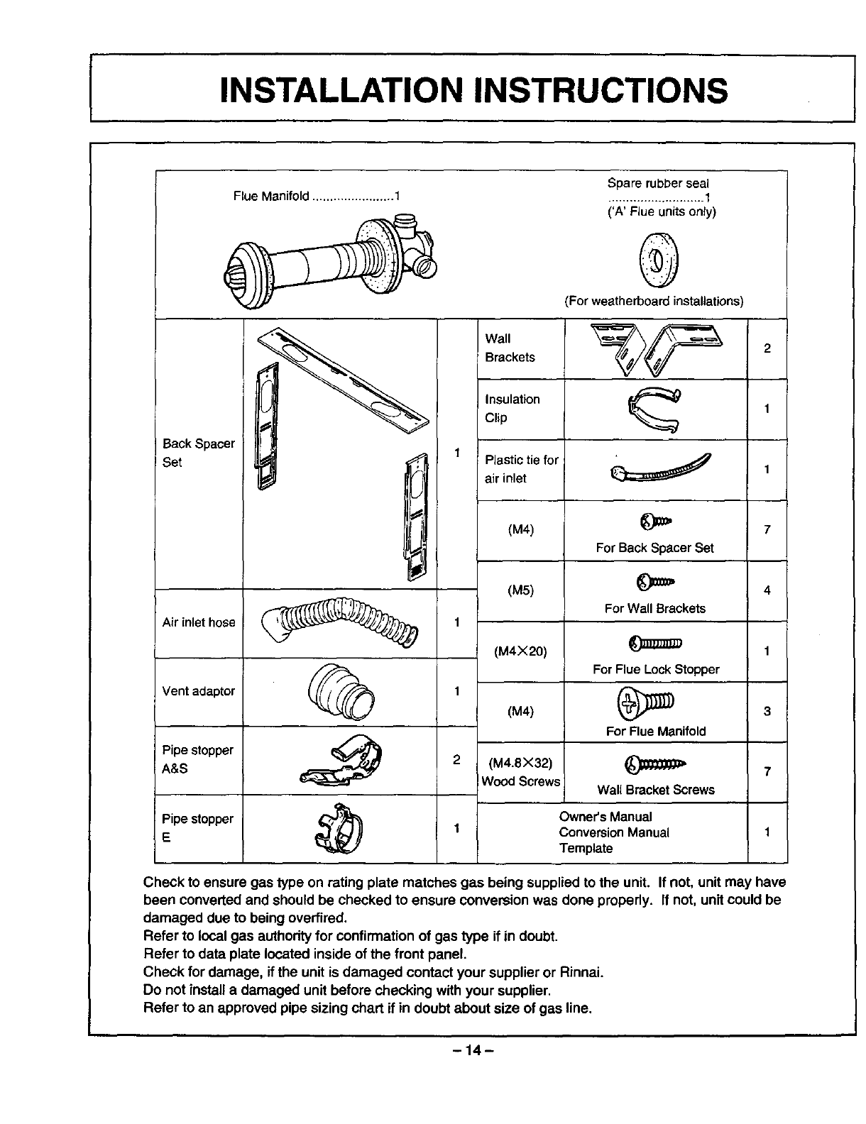
INSTALLATION INSTRUCTIONS I
Flue Manifold .......................1 Spare rubber seal
........................... f
('A' Flue units only)
@
(For weatherboard installations)
Back Spacer
! Set
Wall
Brackets
Pipe stopper
A&S
I._. 1Plastic tie forf air inlet
i J
Air inlet hose 1
Vent adaptor 1
2
Pipe stopper
E
(M4)
(M5)
(M4X20)
(M4)
(M4.8X32)
WoodScrews
7
For Back SpacerSet
4
For Wall Brackets
1
For Flue LockStopper
For Flue Manifold
Wall BracketScrews
Owner'sManual
1 ConversionManual
Template
Check to ensure gas type on rating plate matches gas being supplied to the unit. If not, unit may have
been converted and should be checked to ensure conversion was done properly. If not, unit could be
damaged due to being overtired.
Refer to local gas authority for confirmation of gas type if in doubt.
Refer to data plate located inside of the front panel.
Check for damage, if the unit is damaged contact your supplier or Rinnai.
Do not install a damaged unit before checking with your supplier.
Refer to an approved pipe sizing chart if in doubt about size of gas line.
-14-
GAS CONNECTION I
1. The gas supply line shall be gas-tight, sized and so installed as to provide a supply of gas sufficient
to meet the maximum demand of the heater without loss of pressure.
2. A shut off valve (and appliance connector valve) should be installed in the upstream of the gas line
to permit servicing.
3. Flexible pipe and any appliance connector valve used for gas piping shall be types approved by
nationally recognized agencies.
4. Any compound used on the threaded joint of the gas piping shall be a type which resists the action
of liquefied petroleum gas.
5. Supplied gas pressure must be within the limits shown in the specifications.
6. After completion of gas pipe connections, all joints including the heater must be checked for gas
tightness by means of leak detector solution, soap and water, or an equivalent nonflammable
solution, as applicable.
CAUTION: Since some leak test solutions, including soap and water, may cause corrosion or stress
cracking, the piping shall be rinsed with water after testing, unless it has been determined that the
leak test solution is noncorrosive.
7.
,
The appliance and its appliance main gas valve must be disconnected from the gas supply piping
system during any pressure testing of that system at test pressures in excess of 1/2 P.S.I (3.SkPa).
The appliance must be isolated from the gas supply piping system by closing its individual manual
shut off valve dudng any pressure testing of the gas supply system at test pressures equal to or less
than 1/2 psig.
One 1/8" test plug is provided for testing of manifold pressure see schematic for location. (On page 43,
item # 125)
At time of installation installer must supply a 1/8" N.P.T. plugged tapping, accessible for test
manometer connection, immediately up stream of the gas supply connection to the appliance.
-15-
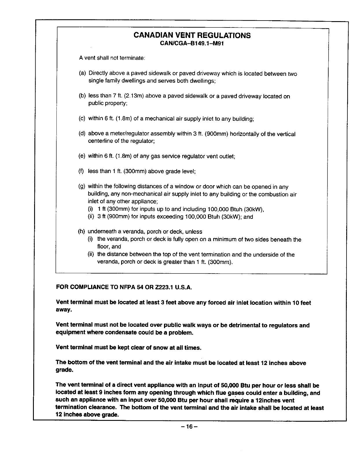
CANADIAN VENT REGULATIONS
CAN/CGA-B149.1 -M9t
A vent shall not terminate:
(a) Directly above a paved sidewalk or paved driveway which is located between two
single family dwellings and serves both dwellings;
(b) less than 7 ft. (2.13m) above a paved sidewalk or a paved driveway located on
public property;
(c) within 6 ft. (1.8m) of a mechanical air supply inlet to any building;
(d) above a meter/regulator assembly within 3 ft. (900mm) horizontally of the vertical
centerline of the regulator;
(e) within 6 ft. (1.8m) of any gas service regulator vent outlet;
(f) less than 1 ft. (300mm) above grade level;
(g) within the following distances of a window or door which can be opened in any
building, any non-mechanical air supply inlet to any building or the combustion air
inlet of any other appliance;
(i) 1 ft (300mm) for inputs up to and including 100,000 Btuh (30kW),
(ii) 3 ft (900ram) for inputs exceeding 100,000 Btuh (30kW); and
(h) underneath averanda, porch or deck, unless
(i) the veranda, porch or deck is fully open on aminimum of two sides beneath the
floor, and
(ii) the distance between the top of the vent termination and the underside of the
veranda, porch or deck is greater than 1 ft. (300ram).
FOR COMPLIANCE TO NFPA 54 OR Z223.1 U.S.A.
Vent terminal must be located at least 3 feet above any forced air inlet location within 10 feet
away.
Vent terminal must not be located over public walk ways or be detrimental to regulators and
equipment where condensate could be a problem.
Vent terminal must be kept clear of snow at all times.
The bottom of the vent terminal and the sir intake must be located at least 12 inches above
grade.
The vent terminal of a direct vent appliance with an input of 50,000 Btu per hour or less shall be
located at least 9 inches form any opening through which flue gases could enter a building, and
such an appliance with an input over 50,000 Btu per hour shall require a 12inches vent
termination clearance. The bottom of the vent terminal and the air intake shall be located at least
12 inches above grade.
-16-
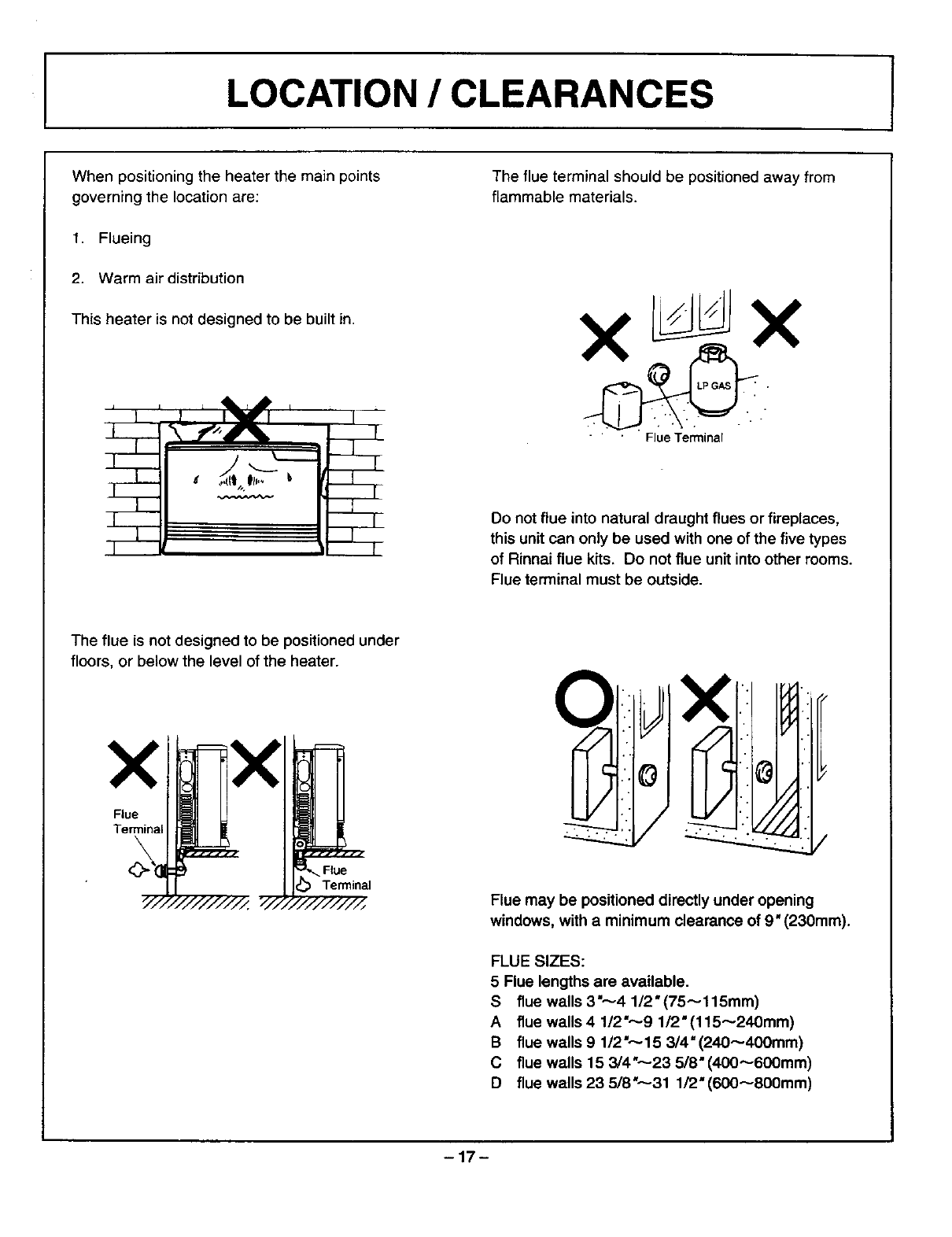
ILOCATION /CLEARANCES
When positioning the heater the main points
governing the location are:
1. Flueing
2. Warm air distribution
This heater is not designed to be built in.
The flue is not designed to be positioned under
floors, or below the level of the heater.
The flue terminal should be positioned away from
flammable materials.
" " Flue Terminal
Do not flue into natural draught flues or fireplaces,
this unit can only be used with one of the five types
of Rinnai flue kits. Do not flue unit into other rooms.
Flue terminal must be outside.
Flue may be positioned directly under opening
windows, with a minimum clearance of 9" (230mm).
FLUE SIZES:
5 Flue lengths are available.
S flue walls 3",-,-4 1/2"(75_115mm)
A flue walls 4 1/2"_9 112" (115_240mm)
B flue walls 9 1/2",---15 3/4"(240_400mm)
C flue walls 15 3/4"---23 5/8"(400_600mm)
D flue walls 23 5/8"---31 1/2"(600_800mm)
-17-
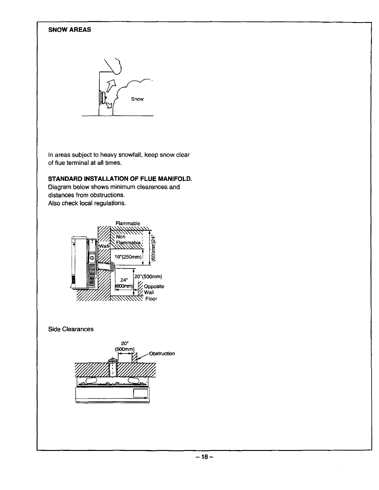
SNOW AREAS
In areas subject to heavy snowfall, keep snow clear
of flue terminal at all times.
STANDARD INSTALLATION OF FLUE MANIFOLD.
Diagram below shows minimum clearances and
distances from obstructions.
Also check local regulations.
Flammable
_///'Jk_ Non '/_"
_,.-'/.,_ Flammable :I_
all ", E
24
Y/////////_.,,.._..._.L_ Wall
_///i///////'X_\\\\\\'x.\\"_ Floor
Side Clearances
20"
(500mm)
-18-

SLEEVE AND MANIFOLD INSTALLATION
METHOD FOR STANDARD WALLS
1. Disassemble Manifold from Sleeve.
The flue consists of 3 parts, sleeve, inside connectors
and tube, outside terminal; (dis-assembly by pulling
hard on outside terminal and inner connections, then
pull sleeve off outer terminal.)
2. Adjustment of Sleeve Length.
Measure walt thickness through previously drilled 3 1/8"
(80mm) hole.
End of sleeve should protrude 3/16"'--3/8" (5_10ram)
from outside wall. Adjust sleeve length to wall
thickness plus 3/16"--3/8"(5_10mm). (Sleeve is
threaded for adjustment.) Do not extend beyond red
line.
3. For S and A flue only.
Depending on flue set and wall thickness extension
piece =C"may need to be removed.
Cut plastic, remove extension, then follow instruction 2.
This applies to "S" and "A" flues only.
There is no extension on other flues, they can be fully
adjusted by tuming the threaded section.
4. Fixing Sleeve.
Fix to the wall, using the 3 screws provided.
NOTE: The flange is marked "TOP", sleeve must be
fitted with this mark Up. Check sleeve protrudes 3/16"
_3/8" (5_- 10mm) on the outside.
Connection Sleeve Terminal
Do not extend
beyond _ line
Extension joint
t'l \under.plastic Extension
!lHJJillfll
Adjust length by turning sleeve.
AB C
Removeextensionat this
"A" Flue only point it necessary.
Fix_,g Screw
5-10ram
.:_
IIIII
:;'::.::1 ; : - "!.:'.':i
: ;'."." ...- ..... -.-....
Don't remove green plastic covering from sleeve.
-19-
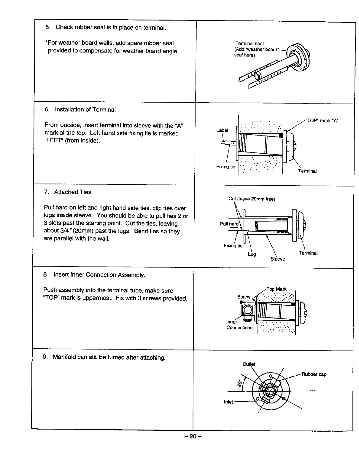
5. Check rubber seal is in place on terminal.
*For weather board walls, add spare rubber seal
provided to compensate for weather board angle.
6. Installation of Terminal
From outside, insert terminal into sleeve with the "A"
mark at the top. Left hand side fixing tie is marked
"LEF'F' (from inside).
7. Attached Ties
Pull hard on left and dght hand side ties, clip ties over
lugs inside sleeve. You should be able to pull ties 2 or
3 slots past the starting point. Cut the ties, leaving
about 3/4"(20mm) past the lugs. Bend ties so they
are parallel with the wall.
8. Insert Inner Connection Assembly.
Push assembly into the terminal tube, make sure
"TOP" mark is uppermost. Fix with 3 screws provided.
9. Manifold can still be turned after attaching.
Terminal seal
(¢dd "weather board"---_
Label
Fixing tie
•.:_'.: ":_..'._:
•, • .... _......_
:..:. :_ :-:.
"TOP" mark "A"
Terminal
Cut (leave 2gram free)
Sleeve
_- Top Mark
_-,_nnections :'"" i'i_''" ?'': ;'.!;" "':
Outlet
Inlet
-20 -
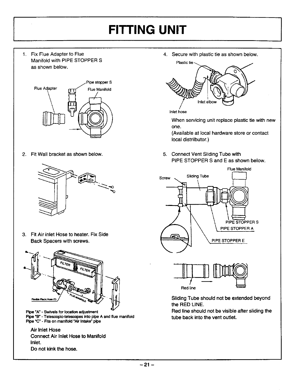
FITTING UNIT
4, Secure with plastic tie as shown below.1. Fix Flue Adapter to Flue
Manifold with PIPE STOPPER S
as shown below.
Inletelbow
Inlet hose
When servicing unit replace plastic tie with new
one.
(Available at local hardware store or contact
local distrilbutor.)
2. Fit Wall bracket as shown below. 5. Connect Vent Sliding Tube with
PIPE STOPPER S and E as shown below.
Flue Manifold
Screw Sliding Tube
PIPE STOPPER S
3. Fit Air inlet Hose to heater. Fix Side
Back Spacers with screws. PIPE STOPPER E
Pipe "A" *Swivels for location adjustment
Pipe "B" -Telescopic-telescopes into pipe A and flue manifold
Pipe "C" - Fits on manifold =Air Intake" pipe
Air Inlet Hose
Connect Air Inlet Hose to Manifold
Inlet.
Do not kink the hose.
Sliding Tube should not be extended beyond
the RED LINE.
Red line should not be visible after sliding the
tube back into the vent outlet.
-21 -

6. Slide the insulation sleeve up to the flue
manifold,slip the securing clip over the sleeve as
shown.
7_ Fix Back Spacer, Top to heater.
(3 screws in top back cover).
•INSTRUCT CUSTOMER ON USE OF HEATER
When you are satisfied that the appliance is
operating correctly, explain operation of heater to
the customer.
Fault-Failure Procedure
If unabte to get the heater to operate correctly,
contact Rinnai directly or your Agent or Gas Utility.
Do not use electrical extension cords to connect unit
to power supply. Keep the power cord away from
the flue.
Some items are not covered under the unit's
warranty. Example: annual maintenance, carbon on
flame rods/igniter, dust, spider webs, improper
conversions, etc.
8. If necessary, the unit can be levelled using the
adjustable legs under the front right and left hand
side legs.
Upto
_djustable Leg
-22-
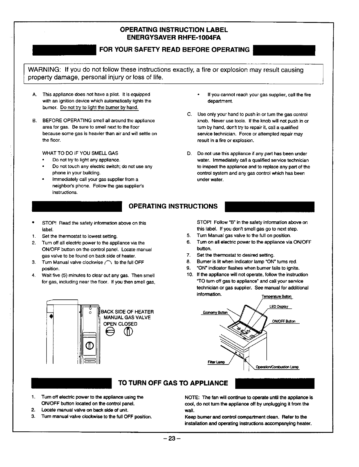
OPERATING INSTRUCTION LABEL
ENERGYSAVER RHFE-1004FA
FOR YOUR SAFETY READ BEFORE OPERATING
WARNING: If you do not follow these instructions exactly, a fire or explosion may result causing
property damage, personal injury or loss of life.
A. This appliance does not have a pilot. It is equipped If you cannot reach your gas supplier, call the fire
with an ignition device which automatically lights the department.
burner, Do not try to light the burner by hand.
B. BEFORE OPERATING smell all around the appliance
area for gas, Be sure to smell next to the floor
because some gas is heavier than air and will settle on
the floor.
WHAT TO DO iF YOU SMELL GAS
Do not try to light any appliance.
Do not touch any electdc switch; do not use any
phone in your building.
immediately call your gas supplier from a
neighbor's phone. Foltow the gas supplier's
instructions.
C. Use only your hand to push in or tum the gas control
knob, Never use tools. If the knob will not push in or
turn by hand, don't try to repair it, call a qualified
service technician. Force or attempted repair may
result in a fire or explosion.
D. Do not use this appliance if any part has been under
water. Immediately call a qualified service technician
to inspect the appliance and to replace any part of the
control system and any gas control which has been
under water.
OPERATING INSTRUCTIONS
•STOP! Read the safety information above on this
label
1. Set the thermostat to lowest setting.
2. Turn off all electdc power to the appliance via the
ON/OFF button on the control panel. Locate manual
gas valve to be found on back side of heater.
3. Turn Manual valve clockwise ('_ to the full OFF
position.
4. Wait five (5) minutes to clear out any gas. Then smell
for gas, including near the floor. If you then smell gas,
o
oBACK SIDE OF HEATER
MANUAL GAS VALVE
OPEN CLOSED
--@®
©
STOP! Follow "B" in the safety information above on
this label. If you don't smell gas go to next step.
5. Turn Manual gas valve to the full on position.
6. Turn on all electric power to the appliance via ON/OFF
button.
7. Set the thermostat to desired setting.
8. Burner is lit when indicator lamp "ON" turns rod.
9. "ON" indicator flashes when burner fails to ignite.
10. If the appliance will nct operate, follow the instruction
"TO turn off gas to appliance" and call your service
technician or gas supplier. See manual for additional
information. T ratureButton
LED "
TO TURN OFF GAS TO APPLIANCE
1. "rum off electhc power to the appliance using the
ON/OFF button located on the control panel.
2. Locate manual valve on back side of unit.
3. Turn manual valve clockwise to the full OFF position.
NOTE: The fan will continue to operate until the appliance is
cool, do not turn the appliance off by unplugging if from the
wall,
Keep burner and control combar_'nent clean. Refer to the
installation and operating instruc_ons accompanying heater.
-23 -
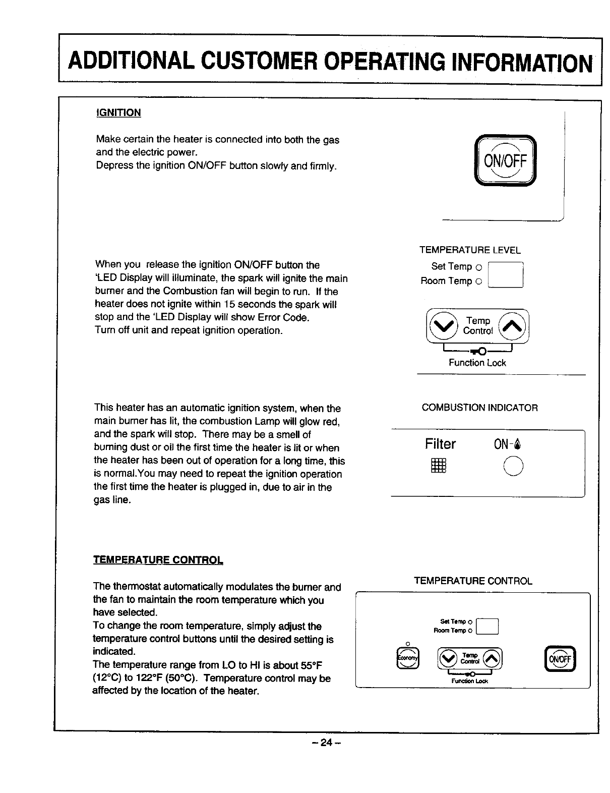
I ADDITIONALCUSTOMEROPERATINGINFORMATIONI
IGNITION
Make certain the heater is connected into both the gas
and the electric power.
Depress the ignition ON/OFF button slowly and firmly.
When you release the ignition ON/OFF button the
'LED Display will illuminate, the spark will ignite the main
bumer and the Combustion fan will begin to run. If the
heater does not ignite within 15 seconds the spark will
stop and the 'LED Display will show Error Code.
Turn off unit and repeat ignition operation.
TEMPERATURE LEVEL
SetTemp©I ]
Room Temp © __
I@ Temp _1
Control
L--_,I,O._.J
Function Lock
This heater has an automatic ignition system, when the
main burner has lit, the combustion Lamp will glow red,
and the spark will stop. There may be a smell of
burning dust or oil the first time the heater is lit or when
the heater has been out of operation for a long time, this
is normal.You may need to repeat the ignition operation
the first time the heater is plugged in, due to air in the
gas line.
COMBUSTION INDICATOR
Filter 0N-
[] 0
TEMPERATURE CONTROL
The thermostat automatically modulates the burner and
the fan to maintain the room temperature which you
have selected.
To change the room temperature, simply adjust the
temperature control buttons until the desired setting is
indicated.
The temperature range from LO to HI is about 55°F
(12°C) to 122°F (50°C). Temperature control may be
affected by the location of the heater.
TEMPERATURE CONTROL
SetTemp 0
RoomTemp 0 [_
0
Func_ Lock
@
-24 -
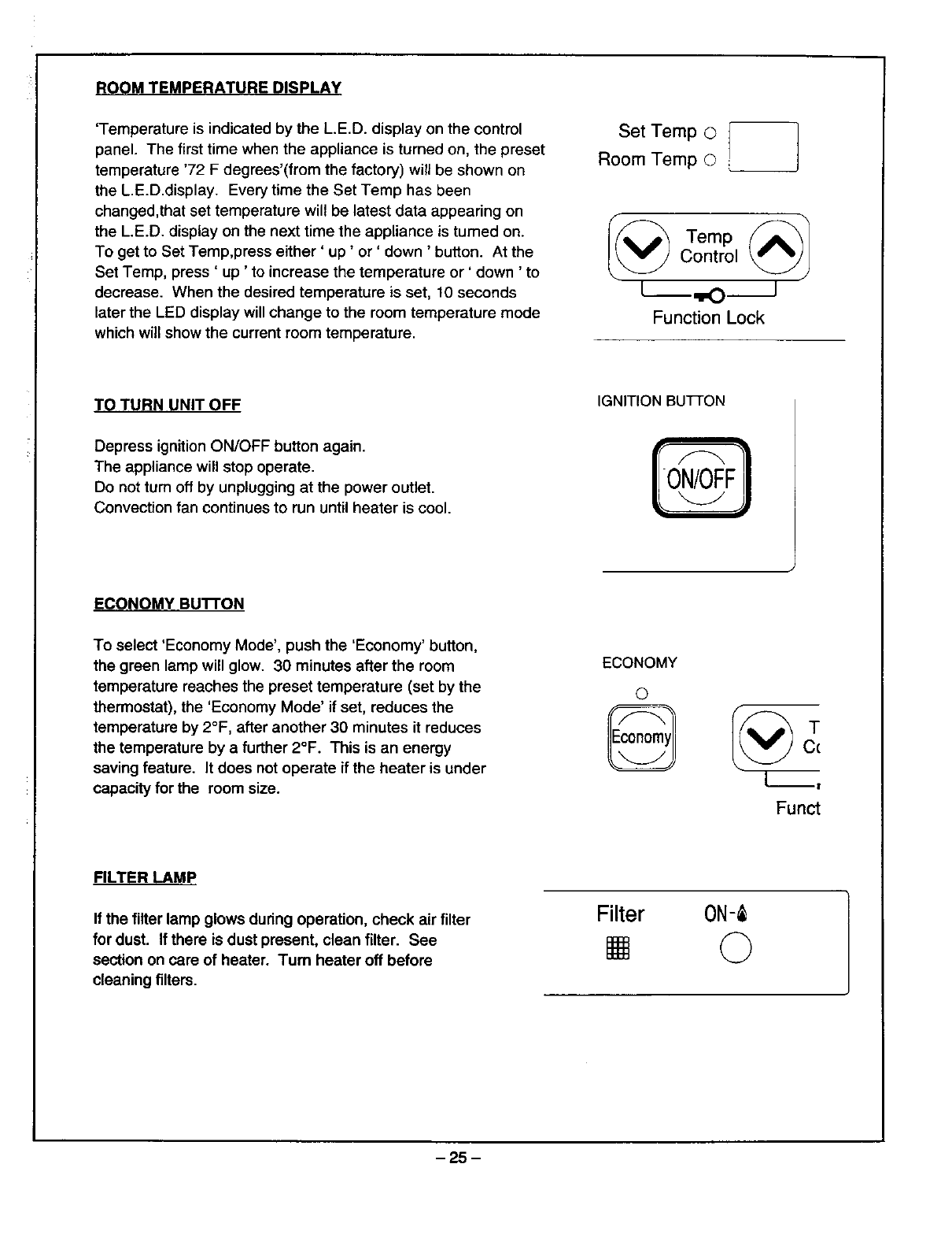
ROOM TEMPERATURE DISPLAY
'Temperature is indicated by the L.E.D. display on the control
panel. The first time when the appliance is turned on, the preset
temperature '72 F degrees'(from the factory) will be shown on
the L.E.D.display. Every time the Set Temp has been
changed,that set temperature will be latest data appearing on
the L.E.D. display on the next time the appliance is turned on.
To get to Set Temp,press either' up' or' down ' button. At the
Set Temp, press ' up 'to increase the temperature or ' down ' to
decrease. When the desired temperature is set, 10 seconds
later the LED display will change to the room temperature mode
which will show the current room temperature.
Set Temp ©
Room Temp O
I(_ Temp _1
Control
[ ,tO J
Function Lock
TO TURN UNIT OFF
Depress ignition ON/OFF button again.
The appliance will stop operate.
Do not turn off by unplugging at the power outlet.
Convection fan continues to run until heater is cool.
IGNITION BUTTON
ECONOMY BUTrON
To select 'Economy Mode', push the 'Economy' button,
the green lamp will glow. 30 minutes after the room
temperature reaches the preset temperature (set by the
thermostat), the 'Economy Mode' if set, reduces the
temperature by 2°F, after another 30 minutes it reduces
the temperature by a further 2°F. This is an energy
saving feature. It does not operate if the heater is under
capacity for the room size.
ECONOMY
©
'_ T
Cc
Funct
FILTER LAMP
If the filter lamp glows dudng operation, check air filter
for dust. If there is dust present, clean filter. See
section on care of heater. Turn heater off before
cleaning filters.
Filter 0N-
0
-25 -
OPERATING PRECAUTIONS
Please read this section carefully, before using your Forced flue heater.
Gas Type, Power Source, and Manufactured Date
• Type of gas, power source and manufactured date are displayed on the nameplate placed on the
right side of the unit.
Do not use gas other than the type of gas (gas group) indicated on the nameplate.
This equipment is for 120 V AC (60Hz) only. Do not use power source other than what is listed.
Caution
•Should the type of gas or power source be different, please contact your dealer. Using a different
type of gas or power source may affect the performance or may be dangerous.
• If you are moving to another area, please check the types of gas and power source provided in the
area. If the types of gas and power source are different, adjustment or modification is necessary.
Please consult the gas provider in the new area.
Usage
Do not use for drying clothes!
Do not use for any other purposes other than heating
(e.g., drying the laundry).
Draping clothes over the unit blocks the warm air outlet or the filter area and is very dangerous,
as it causes heat to build up inside the unit.
Usage Location
•Do not use near flammable material ! ! !
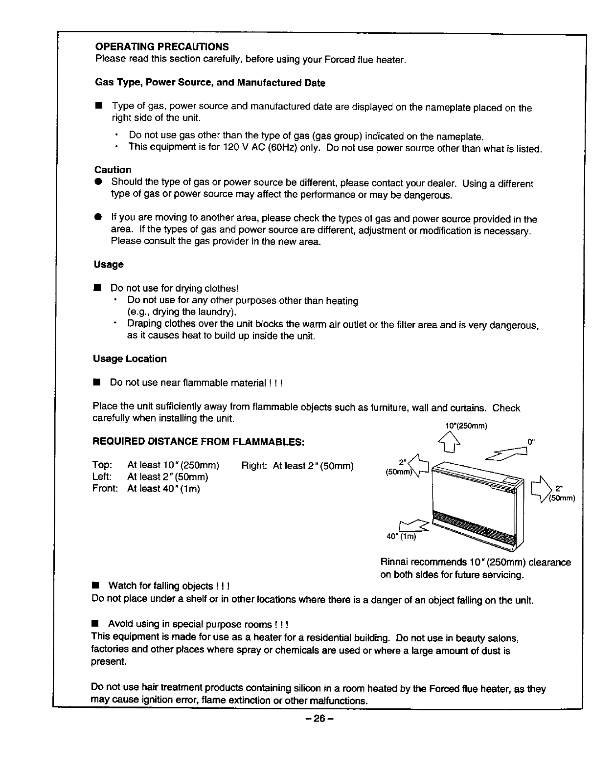
Place the unit sufficiently away from flammable objects such as fumiture, wall and curtains. Check
carefully when installing the unit. 10"(250mm)
REQUIRED DISTANCE FROM FLAMMABLES:
o/L
Top: At least 10" (250mm) Right: At least 2" (50mm) 2-_.Q
Left: At least 2" (50mm) (sore
Front: At least 40" (lm)
°"
40" (lm)
ram)
Rinnai recommends 10" (250mm) clearance
on both sides for future servicing.
•Watch for falling objects ! ! !
Do not place under a shelf or in other locations where there is a danger of an object falling on the unit.
•Avoid using in special purpose rooms ! ! !
This equipment is made for use as a heater for aresidential building. Do not use in beauty salons,
factories and other places where spray or chemicals are used or where a large amount of dust is
present.
Do not use hair treatment products containing silicon in a room heated by the Forced flue heater, as they
may cause ignition error, flame extinction or other malfunctions.
-26 -
Insert a board under the unit when placing on carpeted floor ! ! T
This heater may be installed on combustible flooring. When the heater is installed directly on
carpeting, tile or other combustible material other than wood flooring, the heater shall be installed on
a metal or wood panel extending the full width and depth of the heater.
Emergency Procedures:
Stay calm and turn the unit off ! ! !
In case of an emergency (e.g., abnormal overheating of the unit, loud noise), always stay calm, turn the
unit off by pushing the ON/OFF button, close the gas valve and contact your dealer or the Rinnai office
or store near you. i _,._11._ i
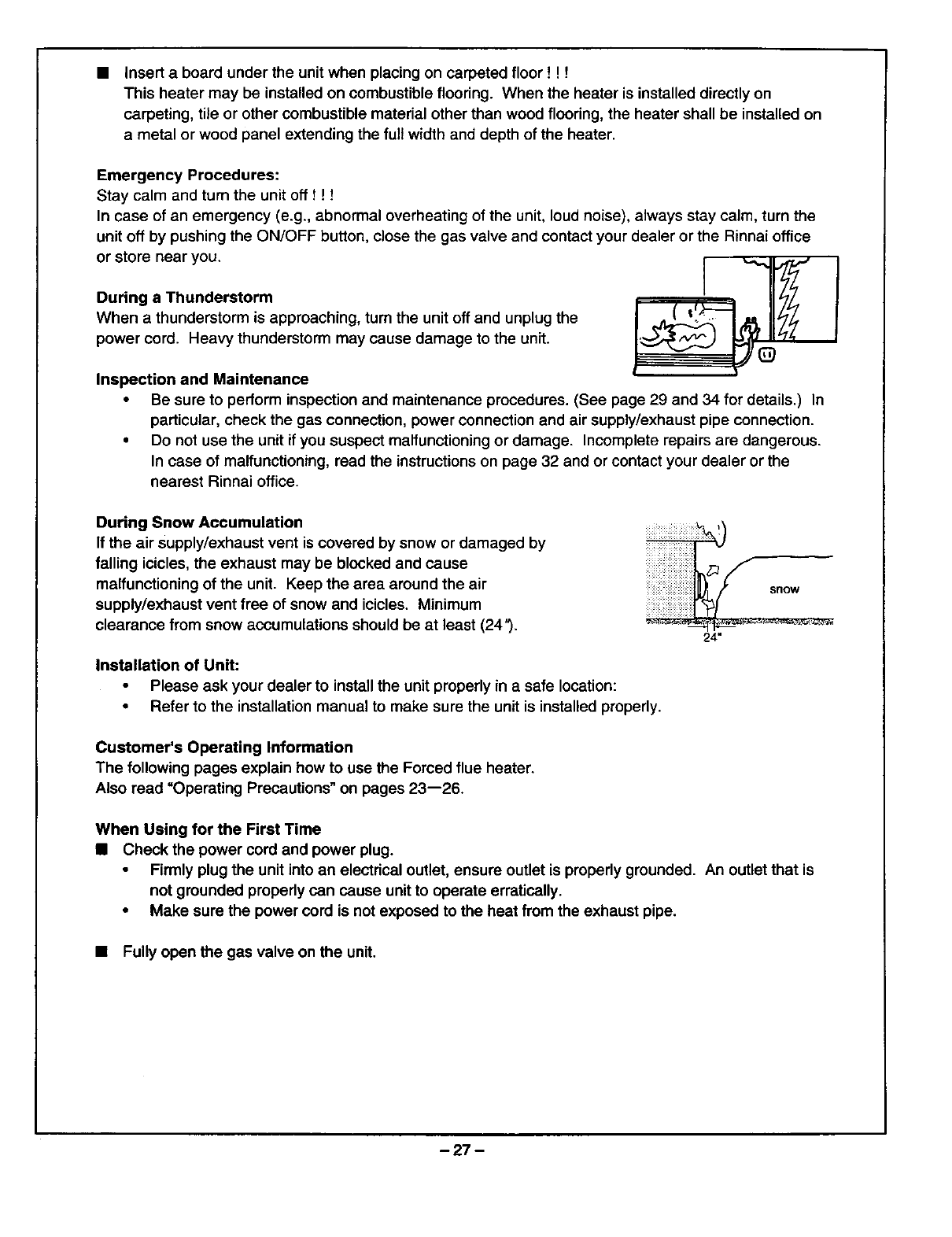
During a Thunderstorm
When a thunderstorm is approaching, turn the unit off and unplug the
power cord. Heavy thunderstorm may cause damage to the unit.
Inspection and Maintenance
Be sure to perform inspection and maintenance procedures. (See page 29 and 34 for details.) In
particular, check the gas connection, power connection and air supply/exhaust pipe connection.
Do not use the unit if you suspect maffunctioning or damage. Incomplete repairs are dangerous.
In case of malfunctioning, read the instructions on page 32 and or contact your dealer or the
nearest Rinnai office.
During Snow Accumulation
If the air supply/exhaust vent is covered by snow or damaged by
falling icicles, the exhaust may be blocked and cause
malfunctioning of the unit Keep the area around the air
supply/exhaust vent free of snow and icicles. Minimum
clearance from snow accumulations should be at least (249.
iii!i i!i iiiiiiiiiiiiiiiiiiiii
snow
24"
Installation of Unit:
•Please ask your dealer to installthe unit properly in a safe location:
• Refer to the installation manual to make sure the unit is installed properly.
Customer's Operating Information
The following pages explain how to use the Forced flue heater.
Also read "Operating Precautions" on pages 23--26.
When Using for the First Time
•Check the power cord and power plug.
•Firmly plug the unit into an electrical outlet, ensure outlet is properly grounded. An outlet that is
not grounded properly can cause unit to operate erratically.
•Make sure the power cord is not exposed to the heat from the exhaust pipe.
•Fully open the gas valve on the unit.
-27-
BeforetheColdSeasonBegins
•Check the air supply/exhaust connection.
•Before using this heater, inspect the air supply/exhaust connection to make sure the pipe is not
disconnected or bent.
• Check the main unit and the air supply/exhaust.
•Make sure there is no combustible or flammable material near the main unit or the air
supply/exhaust.
CAUTION:
If you find a problem with the air supply/exhaust do not use the unit. Contact your dealer or the nearest
Rinnai office.
Function Lock
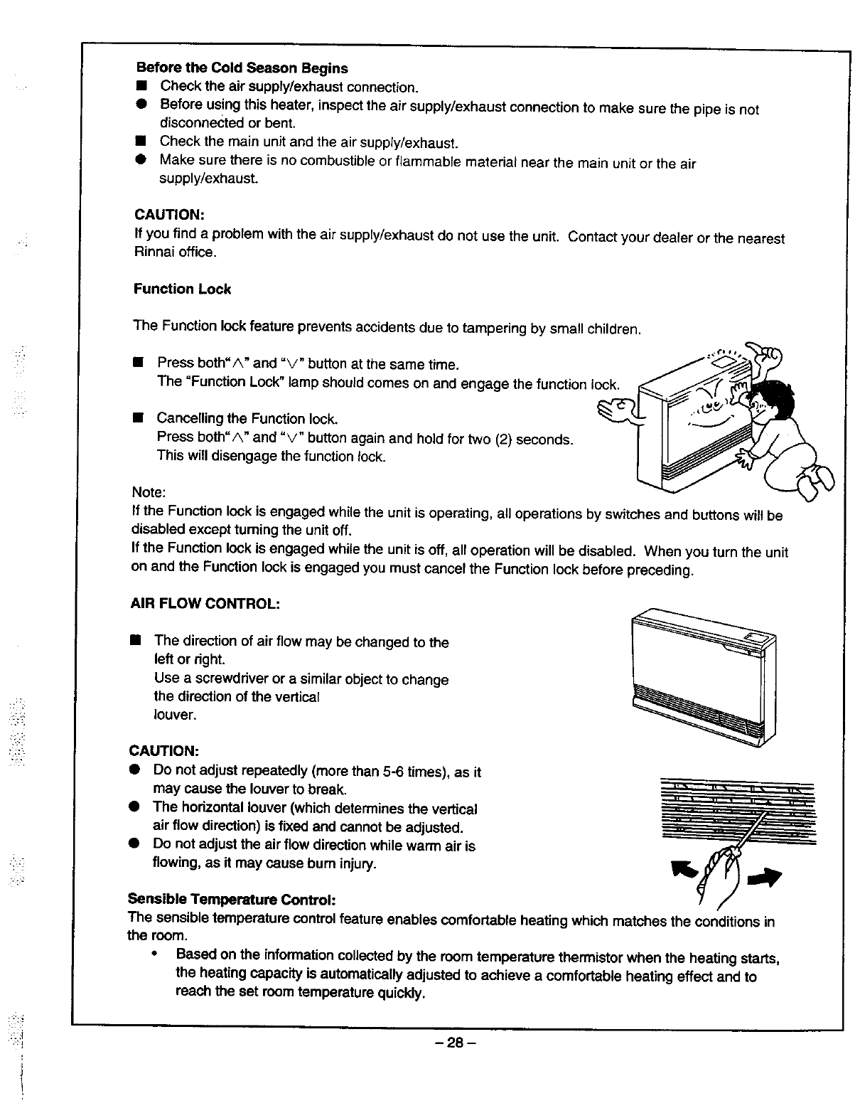
The Function lock feature prevents accidents due to tampering by small children.
• Press both"/k" and %/" button at the same time.
The "Function Lock" lamp should comes on and engage the function lock.
• Cancelling the Function lock.
Press both=A" and %/" button again and hold for two (2) seconds.
This will disengage the function lock.
Note:
If the Function lock is engaged while the unit is operating, all operations by switches and buttons will be
disabled except tuming the unit off.
If the Function lock is engaged while the unit is off, all operation will be disabled. When you turn the unit
on and the Function lock is engaged you must cancel the Function lock before preceding.
AIR FLOW CONTROL:
•The direction of air flow may be changed to the
left or right.
Use a screwdriver or a similar object to change
the direction of the verticaE
louver.
CAUTION:
•DO not adjust repeatedly (more than 5-6 times), as it
may cause the louver to break.
•The hodzontal louver (which determines the vertical
air flow direction) is fixed and cannot be adjusted.
•Do not adjust the air flow direction while warm air is
flowing, as it may cause bum injury. Irb
Sensible Temperature Control:
The sensible temperature control feature enables comfortable heating which matches the conditions in
the room.
• Based on the information collected by the room temperature thermistor when the heating starts,
the heating capacity is automatically adjusted to achieve a comfortable heating effect and to
reach the set room temperature quickly.
-28 -
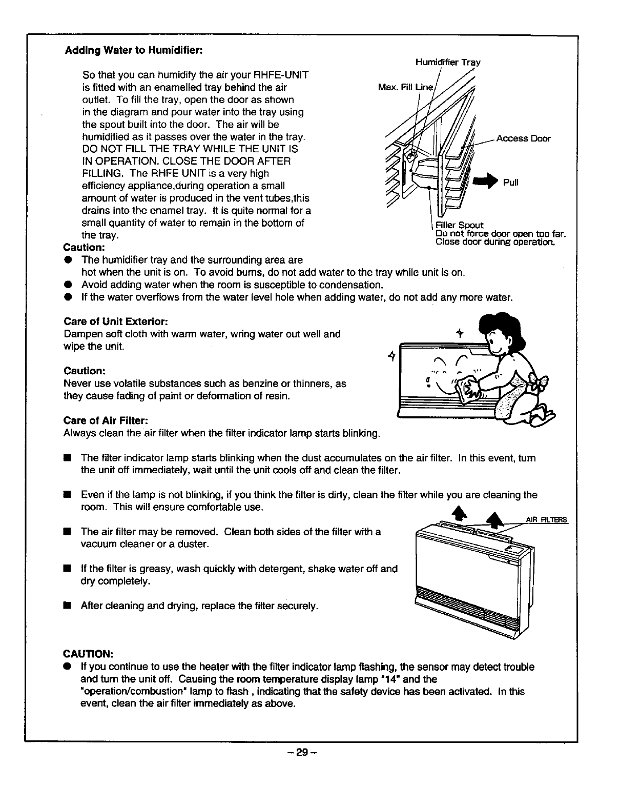
Adding Water to Humidifier:
So that you can humidify the air your RHFE-UNIT
is fitted with an enamelled tray behind the air
outlet. To fill the tray, open the door as shown
in the diagram and pour water into the tray using
the spout built into the door. The air will be
humidified as it passes over the water in the tray.
DO NOT FILL THE TRAY WHILE THE UNIT IS
IN OPERATION. CLOSE THE DOOR AFTER
FILLING. The RHFE UNIT is a very high
efficiency appliance,during operation a small
amount of water is produced in the vent tubes,this
drains into the enamel tray. It is quite normal for a
small quantity of water to remain in the bottom of
the tray.
Caution:
•The humidifier tray and the surrounding area are
Humidifier Tray
Access Door
Pull
1FillerSpout
Do not force door opentoo far.
Close doorduring operation.
hot when the unit is on. To avoid bums, do not add water to the tray while unit is on.
• Avoid adding water when the room is susceptible to condensation.
• If the water overflows from the water level hole when adding water, do not add any more water.
Care of Unit Exterior:
Dampen soft cloth with warm water, wring water out well and
wipe the unit.
Caution:
Never use volatile substances such as benzine or thinners, as
they cause fading of paint or deformation of resin.
Care of Air Filter:
Always clean the air filter when the filter indicator lamp starts blinking.
• The filter indicator lamp starts blinking when the dust accumulates on the air filter. In this event, turn
the unit off immediately, wait until the unit cools off and clean the filter.
Even if the lamp is not blinking, if you think the filter is dirty, clean the filter while you are cleaning the
room. This will ensure comfortable use. _k, ,
AIR RLI_RS
The air filter may be removed. Clean both sides of the filter with a
vacuum cleaner or a duster.
If the tilter is greasy, wash quickly with detergent, shake water off and
dry completely.
After cleaning and drying, replace the filter securely.
CAUTION:
•If you continue to use the heater with the filter indicator lamp flashing, the sensor may detect trouble
and tum the unit off. Causing the room temperature display lamp "14" and the
"operation/combustion" lamp to flash, indicating that the safety device has been activated. In this
event, clean the air filter immediately as above.
-29 -
ITESTING
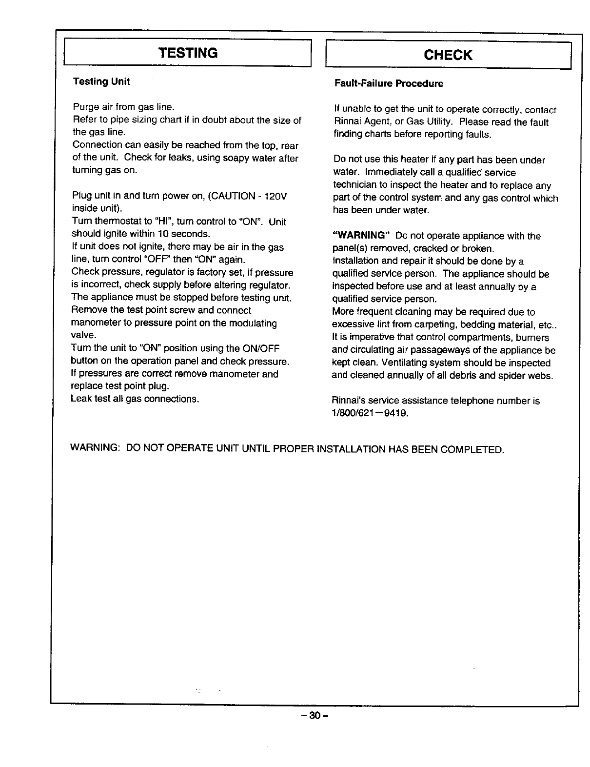
Testing Unit
Purge air from gas line.
Refer to pipe sizing chart if in doubt about the size of
the gas line.
Connection can easily be reached from the top, rear
of the unit. Check for leaks, using soapy water after
turning gas on.
Plug unit in and turn power on, (CAUTION - 120V
inside unit).
Tum thermostat to "HI", tum control to "ON". Unit
should ignite within 10 seconds.
If unit does not ignite, there may be air in the gas
line, turn control "OFP then "ON" again.
Check pressure, regulator is factory set, if pressure
is incorrect, check supply before altering regulator.
The appliance must be stopped before testing unit.
Remove the test point screw and connect
manometer to pressure point on the modulating
valve.
Turn the unit to "ON" position using the ON/OFF
button on the operation panel and check pressure.
If pressures are correct remove manometer and
replace test point plug.
Leak test all gas connections.
ICHECK I
Fault-Failure Procedure
If unable to get the unit to operate correctly, contact
Rinnai Agent, or Gas Utility. Please read the fault
finding charts before reporting faults.
Do not use this heater if any part has been under
water. Immediately call a qualified service
technician to inspect the heater and to replace any
part of the control system and any gas control which
has been under water.
"WARNING" Do not operate appliance with the
panel(s) removed, cracked or broken.
Installation and repair it should be done by a
qualified service person. The appliance should be
inspected before use and at least annually by a
qualified service person.
More frequent cleaning may be required due to
excessive lint from carpeting, bedding material, etc..
It is imperative that control compartments, bumers
and circulating air passageways of the appliance be
kept clean. Ventilating system should be inspected
and cleaned annually of all debris and spider webs.
Rinnai's service assistance telephone number is
1/800/621 --9419.
WARNING: DO NOT OPERATE UNIT UNTIL PROPER INSTALLATION HAS BEEN COMPLETED.
-30-

IPRE-SERVICE CHECK
Before asking for a service calJ please check the following points.
These points are pare of the normal operation of the unit.
•At Ignition:
Heater does not operate. Is the heater plugged in?
Have the fuses or breaker blown at the switch board?
Is there a power failure?
Is the air filter blocked?
is anything blocking the outlet for the hot air?
Is the flue blocked?
The fan is started automatically after a short delay.
This is to allow the heat exchanger to warm up, helping to avoid cold draughts.
This is caused by grease or oil and dust on the heat exchanger and will stop
after a short time.
I This is noise from the heat
simply expansion exchanger.
This is the sound of the solenoid valves opening and closing.
gas
Is the air filter blocked?
Is the set temperature high enough?
Is the warm air outlet blocked by anything?
Are the doors and windows of the room dosed?
Allow heater to coo], clean air filter, operate again.
Even after unit has cooled down the heater does not ignite again. Repair is
necessary.
Contact your local agent or Rinnai for a Service call.
This is to remove the residual heat from the heat exchanger, the fan will stop
when the heater COOlsdown.
High efficiency appliances tend to discharge water vapor on co_ddays, this is
normal
Warmghts.air does not flow when the burner 1
Smoke or strange smells are produced 1
on the f rst tda ght up after nstallation. 1
Sharp clicking noises at ignition, or when
unit cuts down on the thermostat, or goes
out.
•During Combustion:
.d,
,,,1,
operates.Clunkingnoise when the thermostat I m_
[ Unit is not heating room. 1"
Air filter is blocked or the louvers are 1
bocked or obstructed. /
J
Heater will not re-ignite after overheating. ] =1,
•When the unit is turned off.
Convectionfancontinuesto runafter
tumingOFF.
•Other Points:
Steam is o3sdlarged from the flue terminal. I _
Unit cuts off without apparent reason.
IPower Failure.
I _' JCheckwhetherfilteraareblocked,dirtyfilterswiUcausethe heatertooverheat.]
I_I' I Switx:d'lOFF, then ON again when power is restorad to re-set ¢ordrois. ]
-31 -
ITROUBLE SHOOTING I
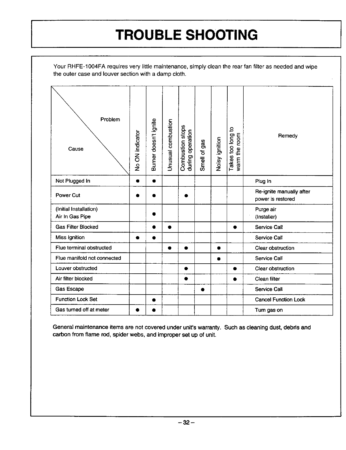
Your RHFE-IOO4FA requires very little maintenance, simply clean the rear fan filter as needed and wipe
the outer case and louver section with a damp cloth.
roblem
-ID 0
Cause _ .-- "o
\z_
o E
0 _
zrn
O
_, (/)
_c o
_E
"Q O')t_ _C: O
o _o2
J= _ "6 ._m ..
0 L1 "--
Remedy
Not Plugged In • • Plug In
Power Cut • • Re-ignite manually after
power is restored
(Initial Installation) Purge air
Air In Gas Pipe • (Installer)
Gas Filter Blocked • • • Service Call
Miss Ignition • • Service Call
Flue terminal obstructed • • • Clear obstruction
Flue manifold not connected Service Call
Louver obstructed • • Clear obstruction
Air filter blocked • • Clean filter
Gas Escape • Service Call
Function Lock Set Cancel Function Lock
Gas turned off at meter • • Turn gas on
General maintenance items are not covered under unit's warranty. Such as cleaning dust, debris and
carbon from flame rod, spider webs, and improper set up of unit.
-32 -
ERROR MESSAGES
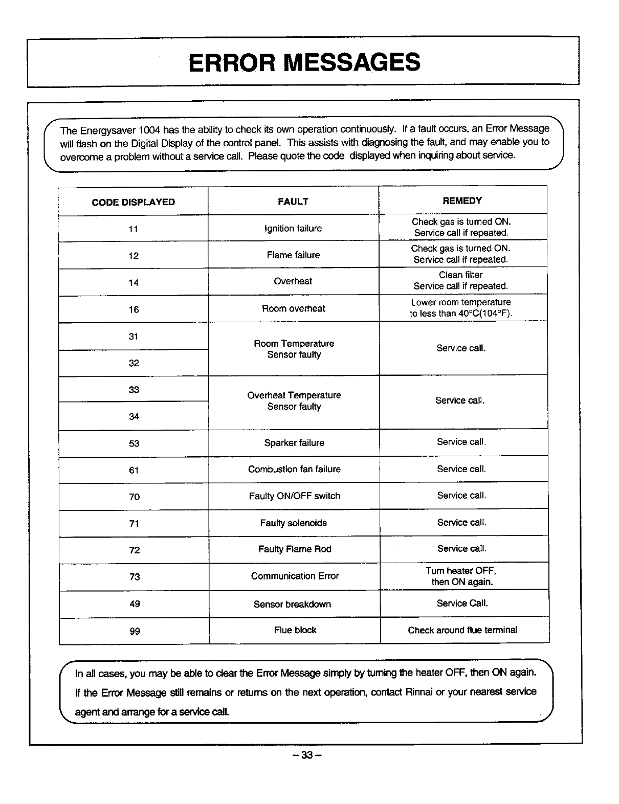
_The Energysaver 1004 has the abilityto check its own operationcontinuously. If a fault occurs,an Error Message
will flash on the Digital Display of the controlpanel. This assists with diagnosingthe fault, and may enable you to |
overcome a problem withouta service call. Please quote the code displayed when inquiring about service, j
FAULT REMEDY
Check gas is turned ON.
Ignition failure Service call if repeated.
Flame failure Check gas is turned ON.
Servicecall if repeated.
Clean filter
Overheat Servicecall if repeated.
Lower room temperature
Room overheat to lessthan 40°C(104°F).
CODE DISPLAYED
11
12
14
16
31
32
33
34
53
61
70
71
72
73
49
99
Room Temperature
Sensor faulty
Overheat Temperature
Sensor faulty
Service call.
Service call.
Sparker failure Service call.
Combustion fan failure Service call.
Faulty ON/OFF switch Service call.
Faulty solenoids Service call.
Faulty Flame Rod Service caII.
Communication Error Turn heater OFF,
then ON again.
Sensor breakdown Service Call.
Flue block Check around flue terminal
I In all cases, you may be able to clear the Error Message simply by tuming the heater OFF, then ON again. '_
J
If the Error Message s_llremains or returns on the next operation, contact Rinnai or your nearest sewice
agent and arrange for a service call.
m33m

IMAINTENANCE /SERVICE
MAINTENANCE SUGGESTIONS
This heater has been designed and constructed for
a long performance life when installed and operated
properly under normal conditions. Regular
inspections, as outlined in this section, are strongly
recommended as means of keeping your heater
operating efficiently throughout the season.
1. Cleaning
Heater must be cleaned annually. Keep heater
clear of dust and debris especially in and around
burner.
Cleaning procedures of heater are as follows:
1) Turn heater off. Allow to cool for one hour.
2) Remove the Front Panel by removing
screws. See schematic page 38.
3) Use pressurized air to remove dust from
around main burner, heat exchangers and
fan blades.
4) Use soft dry cloth to wipe cabinet.
DO NOT DAMAGE OR DISTORT ANY PARTS OF
HEATER.
DO NOT USE WET CLOTH OR SPRAY
CLEANERS ON BURNER.
2. Visual check of main bumer flames.
3_
Flame pattern should be as shown in the
following Figures.
The burner must flame evenly over the entire
surface when operating correctly. The flame
must burn with aclear blue stable flame. See
page 40 item # 417 for location of view ports.
Any and all parts removed for inspection or
service must be replaced before operating unit.
The appliance area must be kept clear and free
from combustible matedals, gasoline and other
flammable vapors and liquids.
4. The flow of combustion and ventilation air should
not be obstructed.
5. Verify proper operation after servicing.
VISUAL CHECK
SATISFACTORY
FRONT VIEW
BLUE FLAME
FLAME ROD
L J
UNSATISFACTORY
FRONT VIEW
YELLOW FLAME
FLAME ROD
• VENT MAINTENANCE
• VENT SYSTEM
Must be checked annually for blockage or
deterioration. See vent installation
instructions for proper assembly.
• MAINTENANCE-ELECTRIC MOTORS
Motors are permanently lubricated and need
no lubrication. Keep fan and motor free of
dust and dirt. Clean annually.
-34-

INDICATORLAMP UNIT
MARK PARTS NAME
MS MAIN SWITCH
R.TH THERMISTOR
TF1 _3 THERMAL FUSE
F FUSE
ER ELECTRODE
POV MODULATING SOLENOID VALVE
TR TRANSFORMER
FR1-3 FLAME ROD 143
MARK PARTS NAME
OH.TH OVER HEAT THERMISTOR
OHS OVER HEAT SWITCH
FM CONVECTION FAN MOTOR
SP SPARKER
SV1 _3 MAIN SOLENOID VALVE 1--3
BL COMBUSTION FAN MOTOR
PS PRESSURE SENSOR
I
I
ER
TEST SW
_R1
ACI20V
If any of the original wire as supplied with the appliance must be
replaced, it must be replaced with a wire of a least a 194°F
temperature rating and number 18AWG or its equivalent.
"CAUTION: Label all wires prior to disconnection when servicing
controls. Wiring errors can cause improper and dangerous operation."
Verify operation after servicing
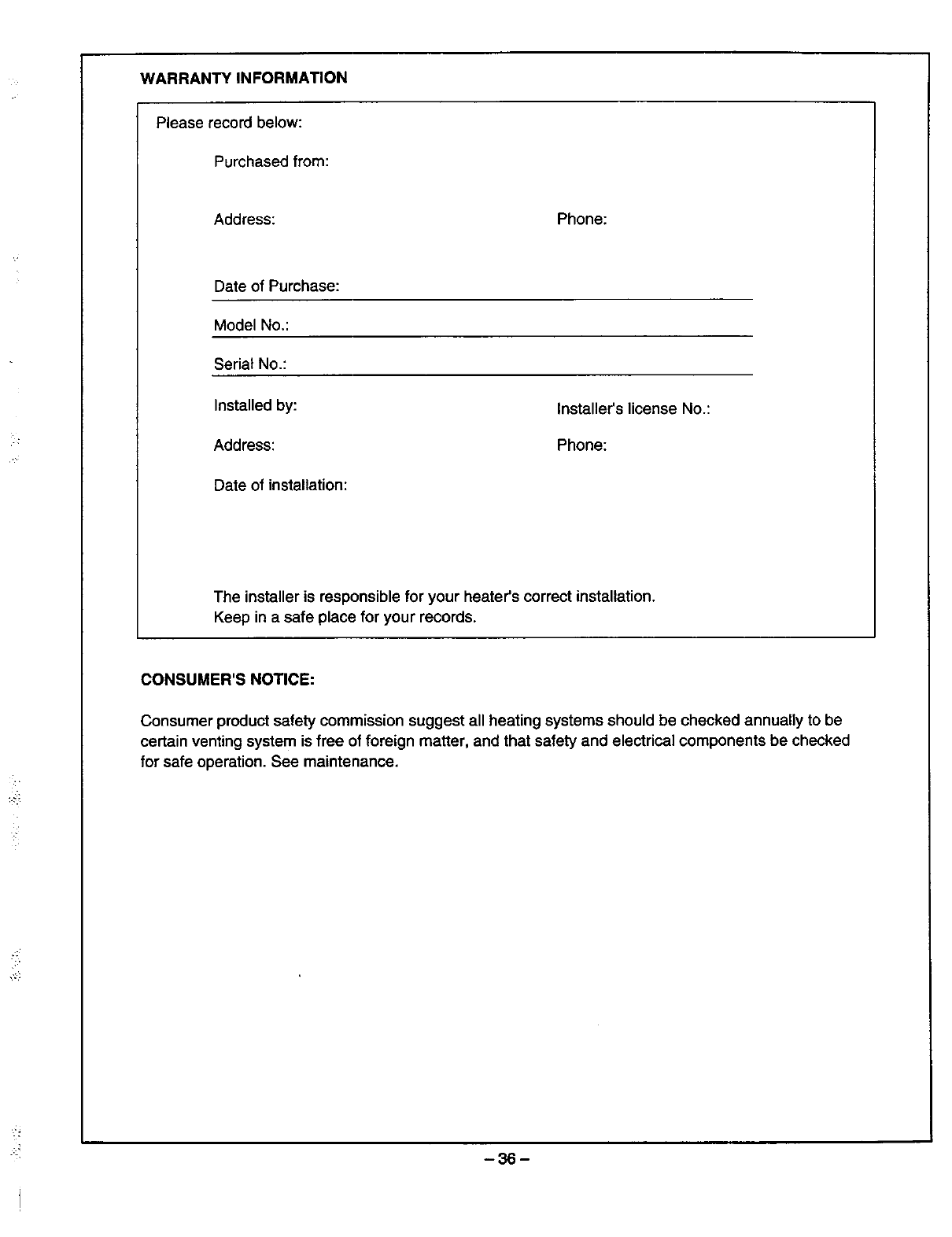
WARRANTY INFORMATION
Please record below:
Purchased from:
Address: Phone:
Date of Purchase:
Model No.:
Serial No.:
Installed by:
Address:
Date of installation:
Installer'slicense No.:
Phone:
The installer is responsible for your heater's correct installation.
Keep in a safe place for your records.
CONSUMER'S NOTICE:
Consumer product safety commission suggest all heating systems should be checked annually to be
certain venting system is free of foreign matter, and that safety and electrical components be checked
for safe operation. See maintenance.
-36-
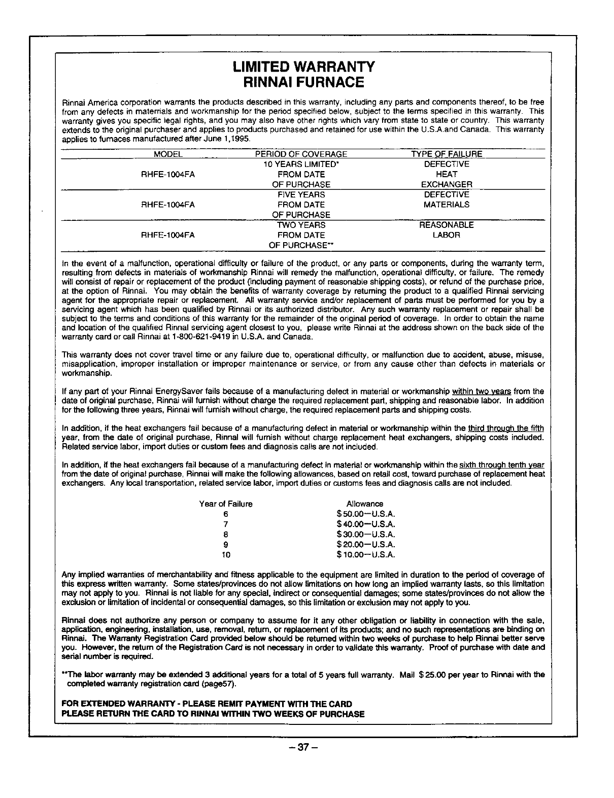
LIMITED WARRANTY
RINNAI FURNACE
Rinnai America corporation warrants the products described in this warranty, including any parts and components thereof, to be free
from any defects in materrials and workmanship for the period specified below, subject to the terms specified in this warranty. This
warranty gives you specific legal hghts, and you may also have other rights which vary from state to state or country. This warranty
extends to the original purchaser and applies to products purchased and retained for use within the U.S.A.and Canada. This warranty
applies to furnaces manufactured after June 1,t995.
MODEL PERIOD OF COVERAGE TYPE OF FAILURE
10 YEARS LIMITED* DEFECTIVE
RHFE-1004FA FROM DATE HEAT
OF PURCHASE EXCHANGER
FIVE YEARS DEFECTIVE
RHFE-1004FA FROM DATE MATERIALS
OF PURCHASE
TWO YEARS REASONABLE
RHFE-1004FA FROM DATE LABOR
OF PURCHASE**
In the event of amalfunction, operational difficulty or failure of the product, or any parts or components, during the warranty term,
resulting from defects in mstedais of workmanship Rinnai will remedy the malfunction, operational difficolty, or failure. The remedy
will consist of repair or replacement of the product (including payment of reasonable shipping costs), or refund of the purchase pdce,
at the option of Rinnai. You may obtain the benefits of warranty coverage by returning the product to a qualified Rinnai servicing
agent for the approphate repair or replacement. All warranty service end/or replacement of parts must be performed for you by a
servicing agent which has been qualified by Rinnsi or its authorized distributor. Any such warranty replacement or repair shall be
subject to the terms and conditions of this warranty for the remainder of the original period of coverage. In order to obtain the name
and location of the qualified Rinnal servicing agent closest to you, please write Rinnai at the address shown on the back side of the
warranty card or call RJnnaJ at 1-800-621-9419 in U.S.A. and Canada.
This warranty does not cover travel time or any failure due to, operational difficulty, or malfunction due to accident, abuse, misuse,
misapplication, improper installation or improper maintenance or service, or from any cause other than defects in materials or
workmanship.
If any part of your Rinnai EnergySaver fails because of a manufacturing defect in material or workmanship within two veers from the
date of original purchase, Rinnai will furnish without charge the required replacement part, shipping and reasonable labor. In addition
for the following three years, Rinnai will furnish without charge, the required replacement parts and shipping costs.
In addition, if the heat exchangers faU because of a manufacturing defect in material or workmanship within the third throuoh the fifth
year, from the date of original purchase, Rinnal will furnish without charge replacement heat exchangers, shipping costs included.
Related service labor, import duties or custom fees and diagnosis calls are not included.
In addition, if the heat exchangers fail because of a manufacturing defect in matedal or workmanship within the sixth throuoh tenth vear
from the date of original purchase, Rinnai will make the following allowances, based on retail cost, toward purchase of replacement heat
exchangers. Any local transportation, related service labor, import duties or customs fees and diagnosis calls are not included.
Year of Failure Allowance
6 $ 50.00--U.S.A.
7$40.00--U.S.A.
8 $ 30.00--U.S.A.
9 $ 2O.00--U.S.A.
10 $10.00-- U.S.A.
Any implied warranties of merchantability and fitness applicable to the equipment are limited in duration to the period of coverage of
this express written warranty. Some states/provinces do not allow limitations on how long an implied warranty lasts, so this limRation
may not apply to you. Rinnai is not liable for any special, indirect or consequential damages; some states/provinces do not allow the
exclusion or limitation of incidental or consequential damages, so this limitation or exclusion may not apply to you.
Rinnal does not authorize any person or company to assume for it any other obligation or liability in connection with the sale,
application, engineering, installation, use, removal, return, or replacement of its products; and no such representations are binding on
Rinnai. The Warranty Registration Card provided below should be retumed within two weeks of purchase to help Rinnai better serve
you. However, the retum of the Registration Card is not necessary in order to validate this warranty. Proof of purchase with date and
serial number is required.
"*The laborwarrantymay be extended3 additionalyearsfor a total of 5 years fullwarranty. Mail $25.00 per year to Rinnaiwiththe
completed warrantyregistrationcard(page57),
FOR EXTENDED WARRANTY - PLEASE REMIT PAYMENT WITH "III'IECARD
PLEASE RETURN THE CARD TO RINNAI WITHIN TWO WEEKS OF PURCHASE
-37-
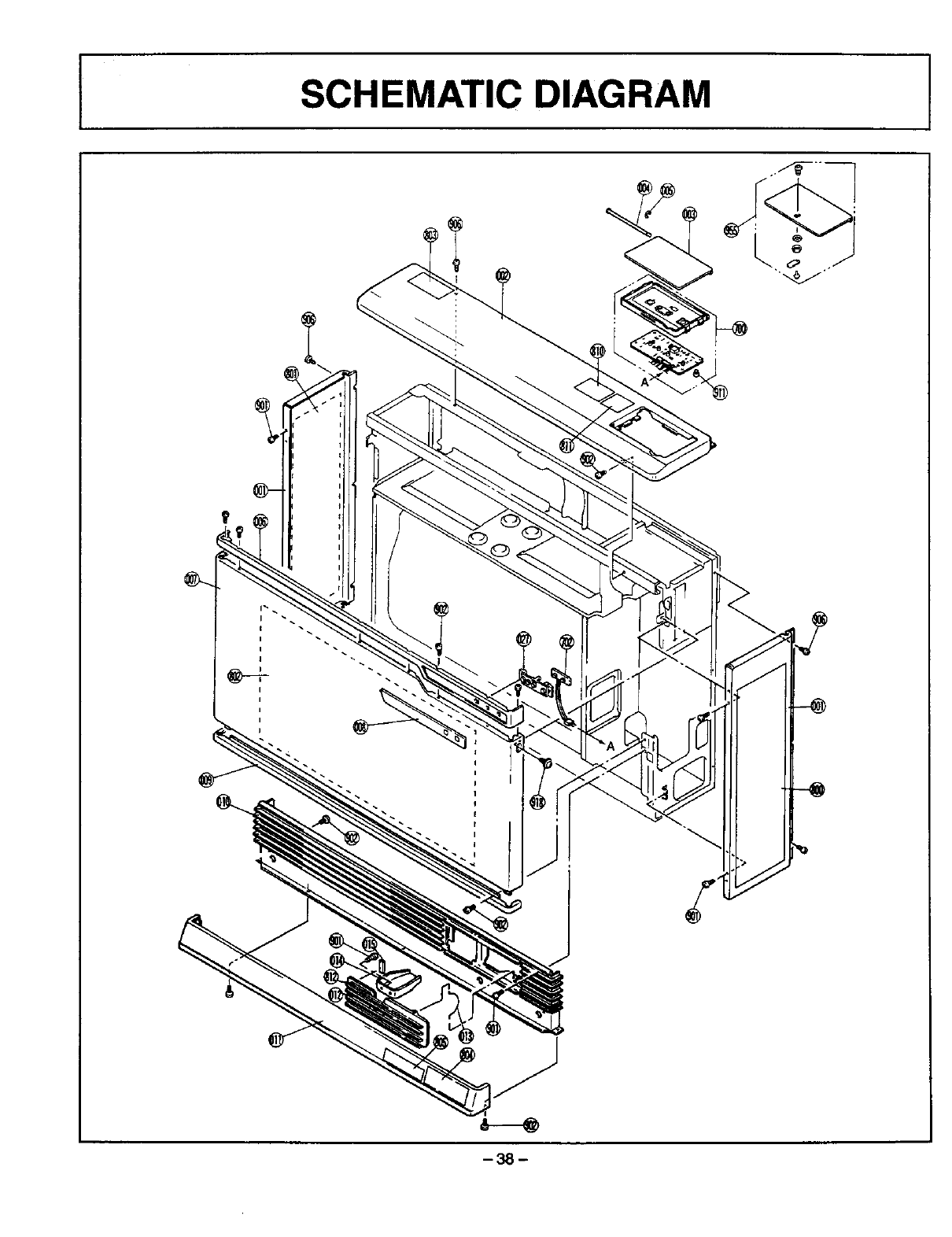
SCHEMATIC DIAGRAM r

_ 39 1
I
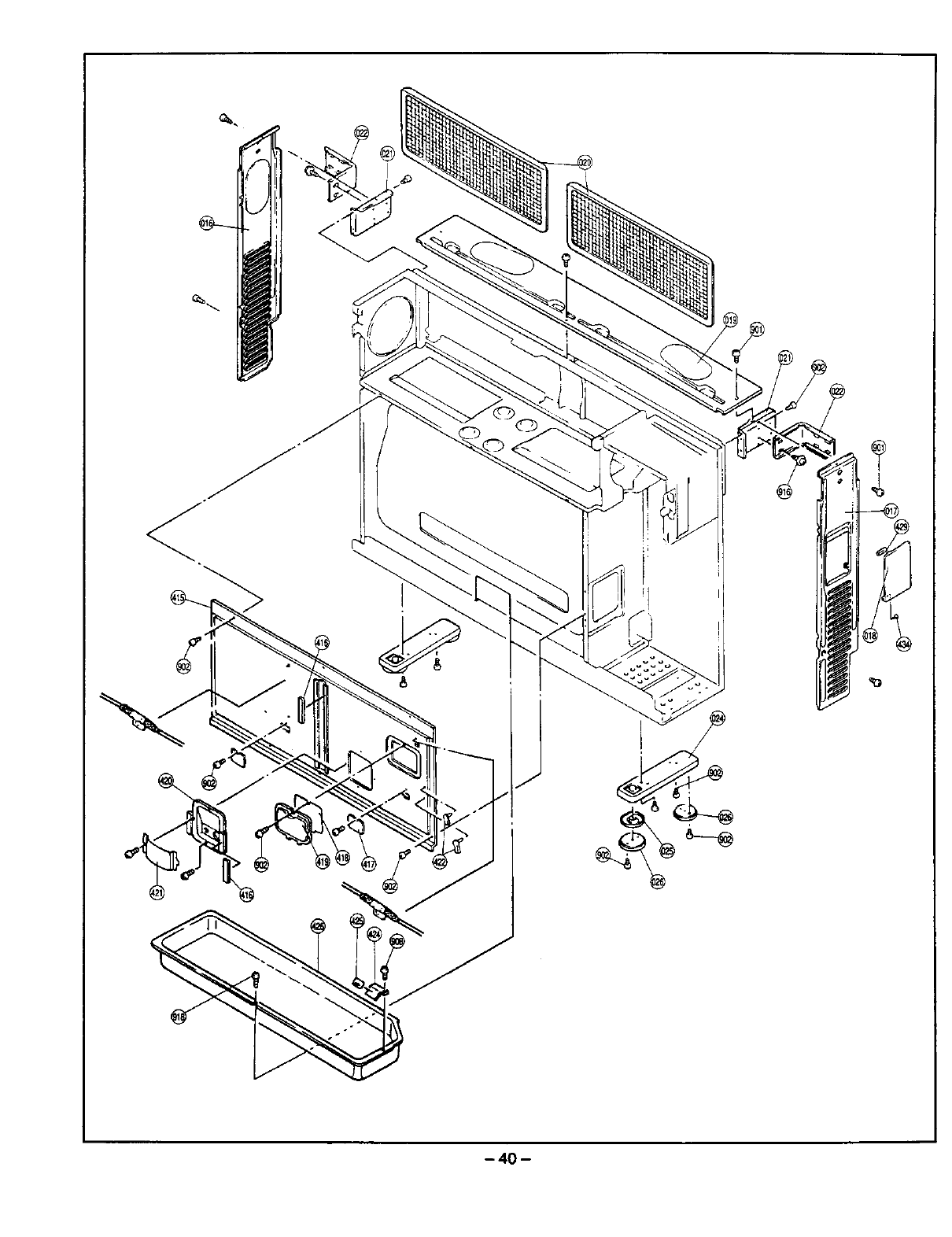
- 40 -
l
/
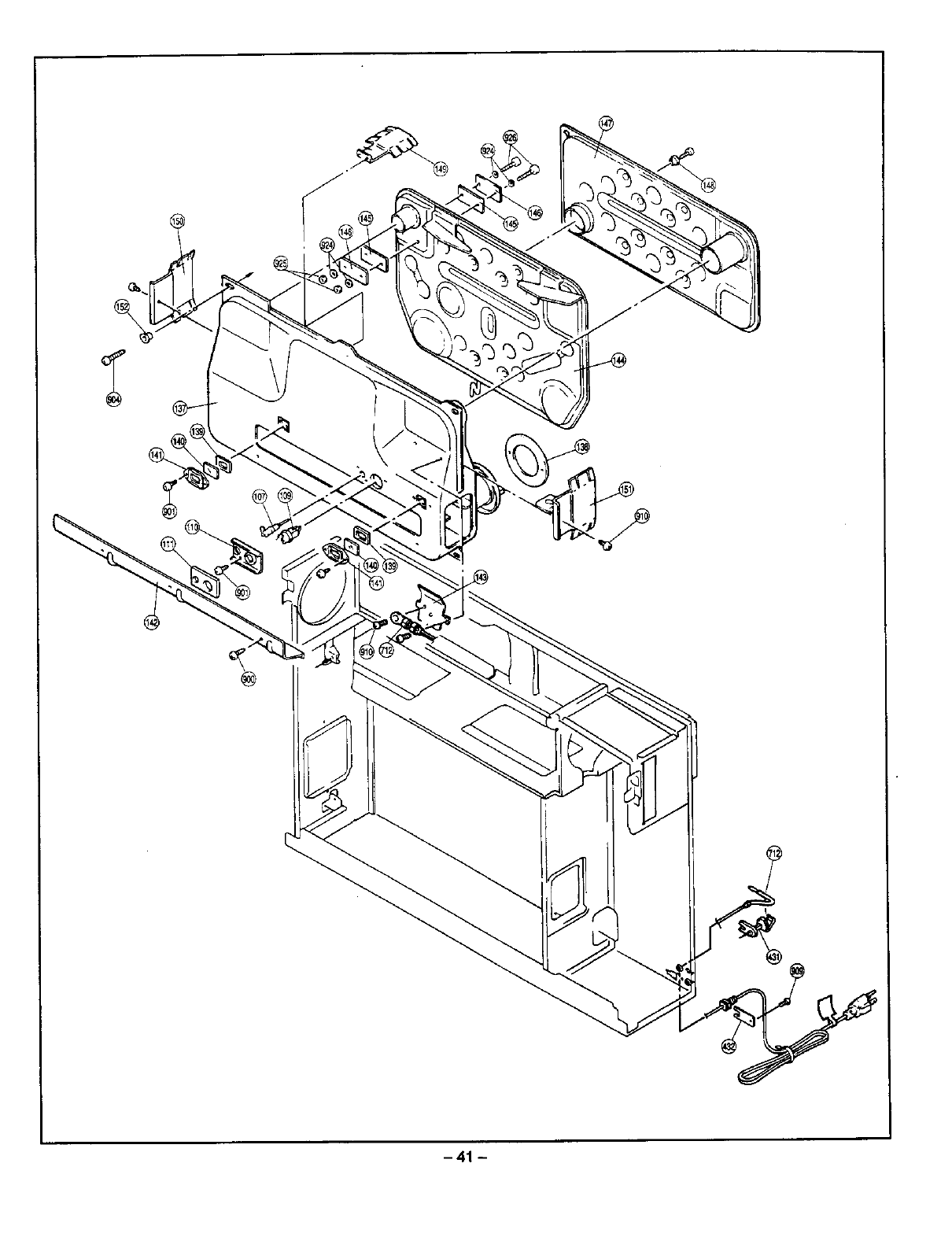
@
-41 -
I
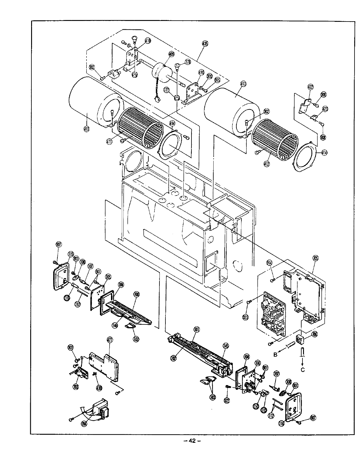
C
- 42 -
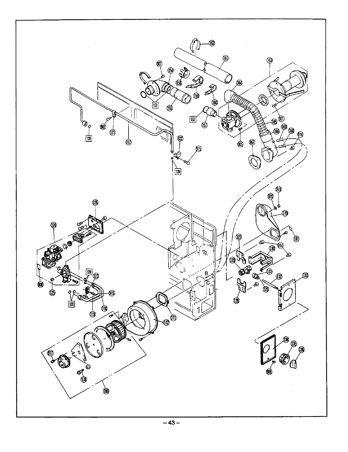
-43-
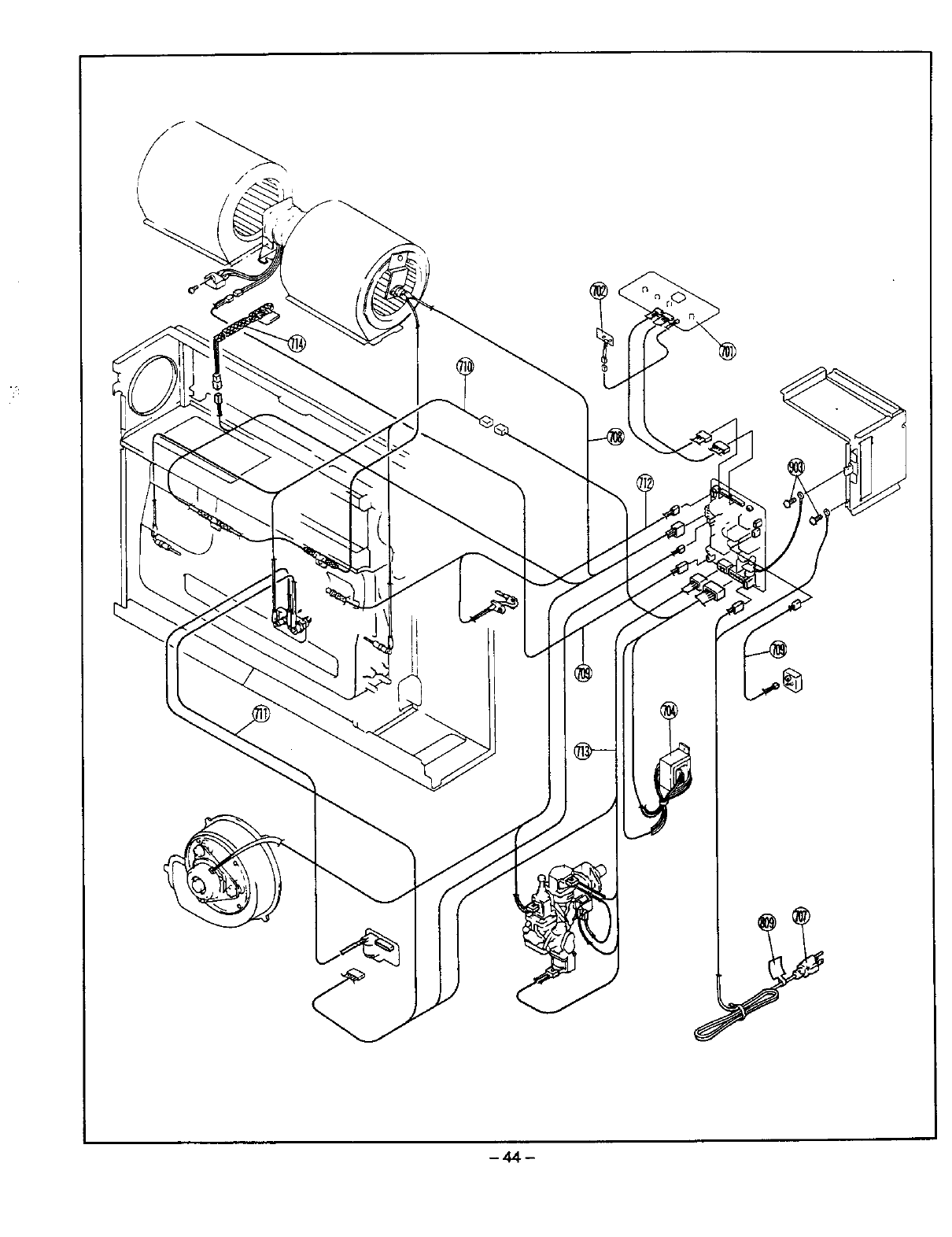
-44-
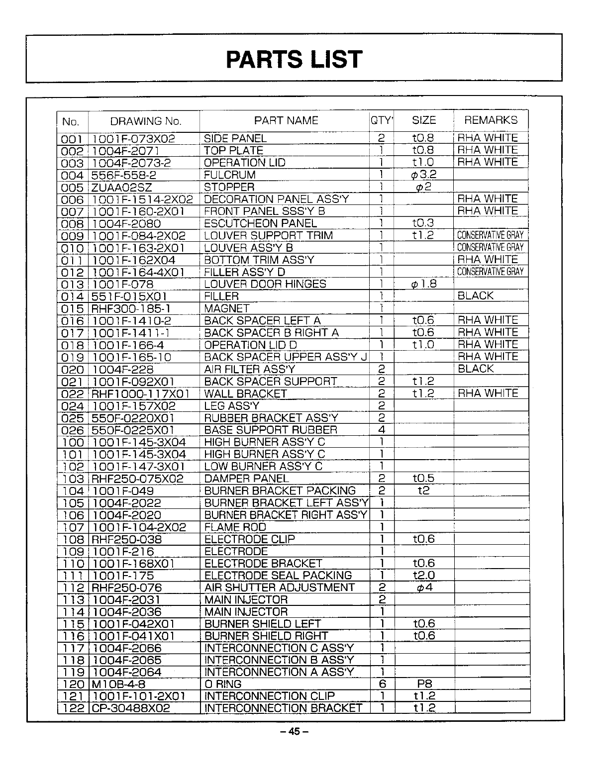
PARTS LIST J
No.
001
002
003
004
005
006
007
008
009
010
011
012
013
014
015
016
017
o18
019
020
021
022
024
025
026
100
101
102
103
]04F
105
106
107
108
1091
110
111
112
113
114
115
116
117
118
119
120
121
122
DRAWING No.
]O01F-O73X02
1004F-207]
1004F-2073-2
556F-558-2
ZUAAO2SZ
]O01F-1514-2X02
]O01F-]60-2XO]
1004F-2080
]O01F-O84-2X02
]O01F-]63-2XO]
]O01F-]62X04
]O01F-]64-4XO]
1001F-078
551F-O]5XO]
RHF300-185-]
1001F-1410-2
lO01F-1411-1
1001F-166-4
100]F-165-10
1004F-228
1001F-O92X01
RHF1000-117X01
lO01F-157X02
550F-O220X01
550F-O225X01
lO01F-145-3X04
1001F-145-3X04
t O01F-147-3X01
RHF250-O75X02
1001F-049
1004F-2022
1004F-2020
]O01F-]O_2X02
RHF250-038
1001F-216
]O01F-]68XO]
1001F-175
RHF250-076
1004_2031
11004R2036
1001_042X01
ilO01_041XO1
1004_2066
1004F-2065
1004F-2064
MlOB4-8
1001F-101-2X01
CP-30488X02
PART NAME
SIDE PANEL
TOP PLATE
OPERATION LID
FULCRUM
STOPPER
DECORATION PANEL ASS'Y
FRONT PANEL SSS'Y B
ESCUTCHEON PANEL
LOUVER SUPPORT TRIM
LOUVER ASS'Y B
BOTTOM TRIM ASS'Y
FILLER ASS'Y D
LOUVER DOOR HINGES
FILLER
MAGNET
BACK SPACER LEFT A
BACK SPACER B RIGHT A
OPERATION LID D
BACK SPACER UPPER ASS'Y J
AIR FILTER ASS'Y
BACK SPACER SUPPORT
WALL BRACKET
LEG ASS'Y
RUBBER BRACKET ASS'Y
BASE SUPPORT RUBBER
HIGH BURNER ASS'Y C
HIGH BURNER ASS'Y C
LOW BURNER ASS'Y C
DAMPER PANEL
BURNER BRACKET PACKING
BURNER BRACKET LEFT ASS'_
BURNER BRACKET RIGHT ASS'Y
FLAME ROD
ELECTRODE CLIP
ELECTRODE
ELECTRODE BRACKET
ELECTRODE SEAL PACKING
AIR SHUTTER ADJUSTMENT
MAININJECTOR
MAININJECTOR
BURNER SHIELD LEFT
BURNER SHIELD RIGHT
INTERCONNECTION C ASS'Y
INTERCONNECTION B ASS'Y
]NTERCONNECTION A ASS'Y
0 RING
INTERCONNECTION CLIP
INTERCONNECTION BRACKET
QTY'
1
1
1
1
1
1
1
1
1
1
1
1
1
1
1
1
2
2
2
2
2
4
1
1
1
2
2
1
1
1
1
1
1
1
2
2
1
1
1
1
1
1
6
1
1
SIZE
tO.8
tO.8
t1.0
¢3.2
e2
tO.3
t1.2
1.8
tO.6
tO.6
t1.0
t1.2
t1.2
tO.5
t2
tO.6
tO.6
t2.0
€4
tO.6
tO.6
P8
t1.2
t1.2
REMARKS
i RHA WHITE
RHA WHITE
RHA WHITE
RHA WHITE
RHA WHITE
CONSERVATIVEGRAY
!CONSERVATEVEGRAY
RHAWHITE
CONSERVATIVEGRAY
BLACK
RHA WHITE
RHA WHITE
RHA WHITE
RHA WHITE
BLACK
RHA WHITE
-45-
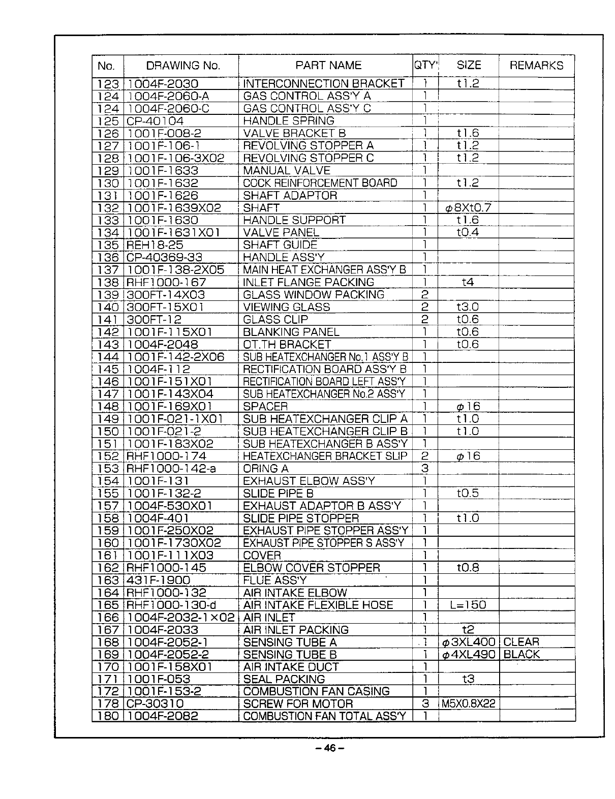
No. DRAWINGNo.
123 1004F-2030
124 l O04F-2060-A
124 1004F-2060-C
125 CP-40104
126 1001F-008-2
127 1001F-106-1
128 lO01F-lO6-3X02
129 1001F-1633
130 1001F-1632
131 1001F-1626
132 1001F-1639X02
133 1001F-1630
134 1001F-1631XO1
135 REH18-25
136 CP-40369-33
137 lO01F-138-2X05
138 RHFlO00-167
139 300FT-14X03
140 300FT-15X01
141 300FT-12
142 1001F-115X01
143 1004F-2048
144 1001F-142-2XO6
145 1004F-112
146 1001F-151X01
147 1001F-143XO4
148 1001F-169XOl
149 lO01FO2]-1X01
150 1001F-02]-2
151 lO01F-183X02
152 RHF1000-174
153 RHF1OOO-142-a
154 1001F-131
155 1001F-132-2
157 lO04F-53OXOl
158 1004F-401
159 1001F-25OX02
160 1001F-1730XO2
161 1001F-111XO3
162 RHF1000-145
163 431F-1900
164 RHF1000-132
165 RHFIOOO-]30-d
166 1004_2032-1x02
167 1004F-2033
168 1004F-2052-1
169 1004F-2052-2
170 1001F-158XO1
17] 1001F-053
]72 ]00]F-]53-2
178 CP-303]0
180 1004F-2082
PARTNAME
INTERCONNECTIONBRACKET
GASCONTROLASS'YA
GASCONTROLASS'YC
HANDLESPRING
VALVEBRACKETB
REVOLVINGSTOPPERA
REVOLVINGSTOPPERC
MANUALVALVE
COCKREINFORCEMENTBOARD
SHAFTADAPTOR
SHAFT
HANDLESUPPORT
VALVEPANEL
SHAFTGUIDE
HANDLEASS'Y
MAINHEATEXCHANGERASS'YB
INLETFLANGEPACKING
GLASSWINDOWPACKING
VIEWINGGLASS
GLASSCLIP
BLANKINGPANEL
OT.THBRACKET
SUBHEATEXCHANGERNo.1ASS'YB
RECTIFICATIONBOARDASS'YB
RECTIFICATIONBOARDLEF ASS'Y
SUBHEATEXCHANGERNo.2ASS'Y
SPACER
SUB HEATEXCHANGERCLIPA
SUB HEATEXCHANGERCLIPB
SUBHEATEXCHANGERB ASS'Y
HEATEXCHANGERBRACKETSLIP
ORINGA
EXHAUSTELBOWASS'Y
SLIDEPIPEB
EXHAUSTADAPTORB ASS'Y
SLIDEPIPESTOPPER
EXHAUSTPIPESTOPPERASS'Y
EXHAUSTPIPESTOPPERSASS'Y
COVER
ELBOWCOVERSTOPPER
FLUEASS'Y
AIRINTAKEELBOW
AIRINTAKEFLEXIBLEHOSE
AIRINLET
AIRINLETPACKING
SENSINGTUBE A
SENSINGTUBE B
AIRINTAKEDUCT
SEALPACKING
COMBUSTIONFAN CASING
SCREWFORMOTOR
COMBUSTIONFANTOTALASS'Y
QTY'! SIZE
I i t1.2
l r
]
]
] t] .6
l t] .2
I i t1.2
]
1 t1.2
1
1 _8XtO.7
1 t1.6
1 tO.4
]
]
]
] t4
2
2 t3.0
2 tO.6
1 tO.6
1 tO.6
1
1
1
1
1 €16
1 t1.0
1 t1.0
1
2 _bl6
3
]
] tO.5
]
l tl .0
l
l
l
1 tO.8
]
]
l L=I 50
1
l t2
t _ 3XL400
l _4XL490
1
] t3
1
3 M5XO.8X22
1
REMARKS
CLEAR
BLACK
-46-
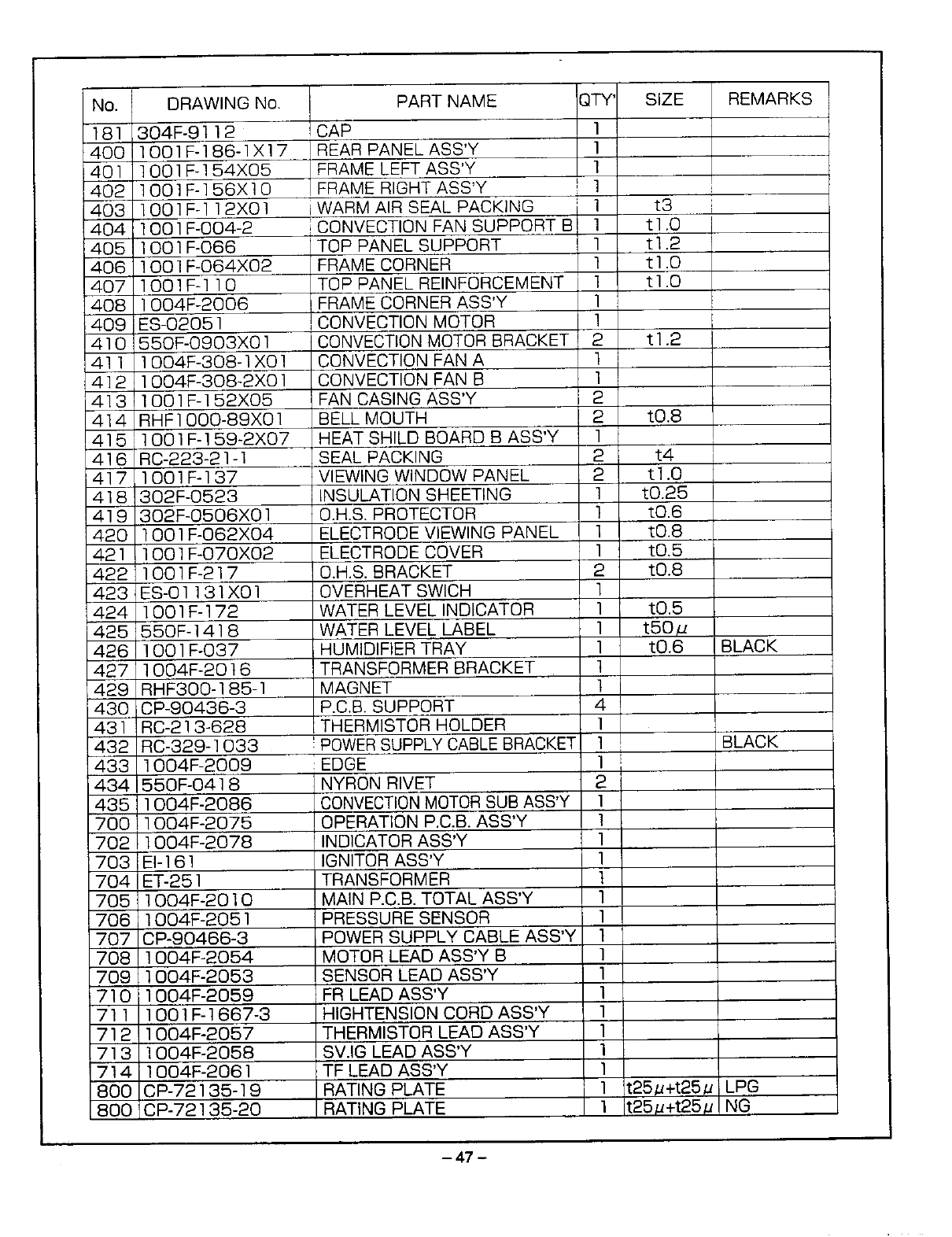
No. DRAWINGNo.
181 304F-g112
400 1001F-186-1X17
401 lO01F-154X05
402 1001F-156X10
403 O01F-]12X01
404 00]F-004-2
405 001F-066
406 O01F-O64X02
4O7 001F-110
408 004F-2006
409 ES-02051
410 550F-OgO3X01
411 O04F-308-1X01
412 l O04F-30B-2X01
413 ;O01F-152X05
414 RHFIOOO-B9X01
415 1001F-159-2X07
416 RC-223-21-1
417 1001F-137
418 302F-0523
419 302F-OBO6X01
420 lO01F-O62X04
421 1001F-OTOX02
i422 1001F-217
423 ES-O1131X01
424 1001F-172
425 550F-141B
426 1001F-037
427 1004F-20t6
429 RHF300-185-1
430_CP-90436-3
431 RC-213-628
432 RC-329-1033
433 1004F-2009
434 550F-0418
435 IO04F-2086
700 004F-2075
702 ]004F-2078
7031E1-161
704 E%251
705 1004F-2010
706 1004F-2051
707 CP-90466-3
708 1004F-2054
709 1004F-2053
710 1004F-2059
711 1001F-1667-3
712 1004F-2057
713 1004F-2058
714 1004F-2061
800 CP-72135-19
800 CP-72135-20
PART NAME 3TY
! CAP
REAR PANEL ASS'Y
FRAME LEFT ASS'Y
FRAME RIGHT ASS'Y !
WARM AIR SEAL PACKING
CONVECTION FAN SUPPORT B
TOP PANEL SUPPORT
FRAME CORNER
TOP PANEL REINFORCEMENT
FRAME CORNER ASS'Y
CONVECTION MOTOR
CONVECTION MOTOR BRACKET
CONVECTION FAN A
CONVECTION FAN B
FAN CASING ASS'Y
BELL MOUTH
HEAT SHILD BOARD B ASS'Y
SEAL PACKING
VIEWING WINDOW PANEL
INSULATION SHEETING
O.H.S. PROTECTOR
ELECTRODE VIEWING PANEL
ELECTRODE COVER
O.H.S. BRACKET
OVERHEAT SWlCH
WATER LEVEL INDICATOR
WATER LEVEL LABEL
HUMIDIFIER TRAY
TRANSFORMER BRACKET
MAGNET
P.C.B. SUPPORT
THERMISTOR HOLDER
! POWER SUPPLY CABLE BRACKET
: EDGE
NYRON RIVET
CONVECTION MOTOR SUB ASS'Y
OPERATION P.C.B. ASS'Y
INDICATOR ASS'Y
IGNITOR ASS'Y
TRANSFORMER
MAIN P.C.B. TOTAL ASS'Y
PRESSURE SENSOR
POWER SUPPLY CABLE ASS'Y
MOTOR LEAD ASS'Y B
SENSOR LEAD ASS'Y
FR LEAD ASS'Y
HIGHTENSION CORD ASS'Y
THERMISTOR LEAD ASS'Y
SV.IG LEAD ASS'Y
TF LEAD ASS'Y
RATING PLATE
RATING PLATE
1
1
1
1
1
1
1
1
1
1
1
2
1
1
2
2
1
2
2
1
1
1
1
2
1
1
1
1
1
1
4
1
1
1
2
1
1
1
1
1
1
1
1
1
1
1
1
1
1
1
1
1
SIZE
t3
tl .0
t1.2
t1.0
t1.0
t1.2
tO.8
t4
t] .0
t0.25
tO.6
tO.8
tO.5
tO.8
tO.5
t50/_
tO.6
t25/_+t25/J
t25/J+t25/J
REMARKS
BLACK
BLACK
LPG
NG
- 47 -
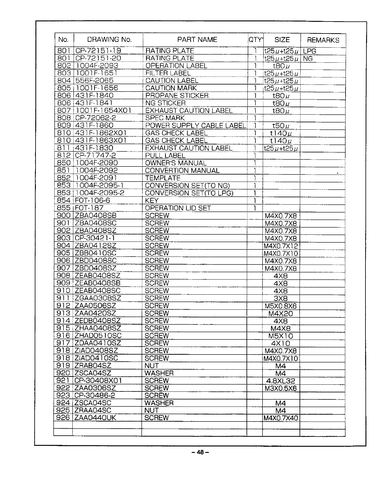
No. DRAWING No. PART NAME
801 CP-72151-19
801 CP-72151-20
802 1004F-2093
!803 1001F-1651
804 556F-2065
805 1001F-1656
8061431F-1840
806 431F-1841
807 ]O01F-]654XO]
808 CP-72062-2
809 431F-1860
S]O 431F-]862XO]
810 431F-]863XO]
811 431F-1830
812 CP-71747-2
850 1004F-2090
851 ]GO4F-2092
852 1004F-2091
853 1004F-2095-1
853 1004F-2095-2
854 FOT-]06-6
855 FOT-187
ZBAO408SB
901900ZBA0408SC
902 ZBAO4OSSZ
903 CP-30421-1
904 ZBAO4]2SZ
905 ZBB04]OSC
906 ZBDO408SC
907 ZBDO408SZ
908 ZEABO408SZ
909 ZEABO408SB
910 ZEAB0408SC
911ZGAAO308SZ
912 ZAAO506SZ
913 ZAAO420SZ
914 ZEDBO4OSSZ
9]5JZHAAO408SZ
916 ZHADO5]OSC
917 ZDAAO4]OSZ
9]8iZlADO408SZ
RATING PLATE
RATING PLATE
OPERATION LABEL
FILTER LABEL
CAUTION LABEL
CAUTION MARK
PROPANE STICKER
NG STICKER
EXHAUST CAUTION LABEL
SPEC MARK I
POWER SUPPLY CABLE LABELi
GAS CHECK LABEL
GAS CHECK LABEL
EXHAUST CAUTION LABEL
PULLLABEL
OWNER'S MANUAL
CONVERTION MANUAL
TEMPLATE
CONVERSION SET(TO NG)
CONVERSION SET_O LPG)
KEY
OPERATION LID SET
SCREW
SCREW
SCREW
SCREW
SCREW
SCREW
SCREW
SCREW
SCREW
SCREW
SCREW
SCREW
SCREW
SCREW
SCREW
SCREW
SCREW
SCREW
SCREW
QTY' SIZE REMARKS
] t25u+t25_ LPG
] _t25/_+t25u_ NG
1 t80u i
] t25u+t25u
] t25/_+t25/_
1 t25u+t25u
] t80u
t80u
t80 u
I
I
I
I
I
I
I
I
I
I
I
I
I
I
I
t5O u
tl40d
t t140U
t25u+t25u
M4XO,7X8
M4XO.TX8
M4XO.7X8
M4XO.7X8
M4XO.7X]2!
M4XO.7X]O
M4XO.7X8
M4XO.7X8
4X8
4X8
4X8
3X8
M5XO.8X6
M4X20
4X8
M4X8
M5X]O
4X10
M4XO.7X8
918
919
920
921
922
923
924i
925
926
ZlADO410SC
ZRABO4SZ
ZSCAO4SZ
C_30408X01
ZAAO306SZ
CP-30486-2
ZSCAO4SC
ZRAA04SC
ZAAO440UK
SCREW
NUT
WASHER
SCREW
SCREW
SCREW
WASHER
NUT
SCREW
M4XO.7X ] 0
M4
M4
4.8XL32
M3XO.5X6
M4
M4
M4XO.7X40
-48-
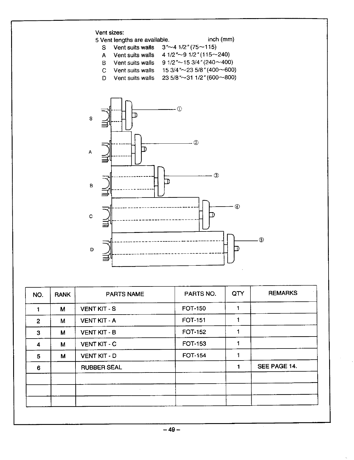
Vent sizes:
5 Vent lengths are available, inch (ram)
S Vent suits walls 3"44 1/2" (75 4115)
A Vent suits walls 41/2"_91/2"(115_240)
B Vent suits walls 9 1/2"----15 3/4" (2404400)
C Vent suits walls 15 3/4"----23 5/8" (40046001
D Vent suits walls 23 5/8"_31 1/2" (6004800/
A
c
D
®
®
®
NO.
1
2
3
4
5
6
RANK
M
M
M
M
M
PARTS NAME
VENT KIT -S
VENT KIT - A
VENT KIT - B
VENT KIT - C
VENT KIT -D
RUBBER SEAL
PARTS NO.
FOT-150
FOT-151
FOT-152
FOT- 153
FOT- 154
QTY
1
1
1
1
1
1
REMARKS
SEE PAGE 14.
-49 -
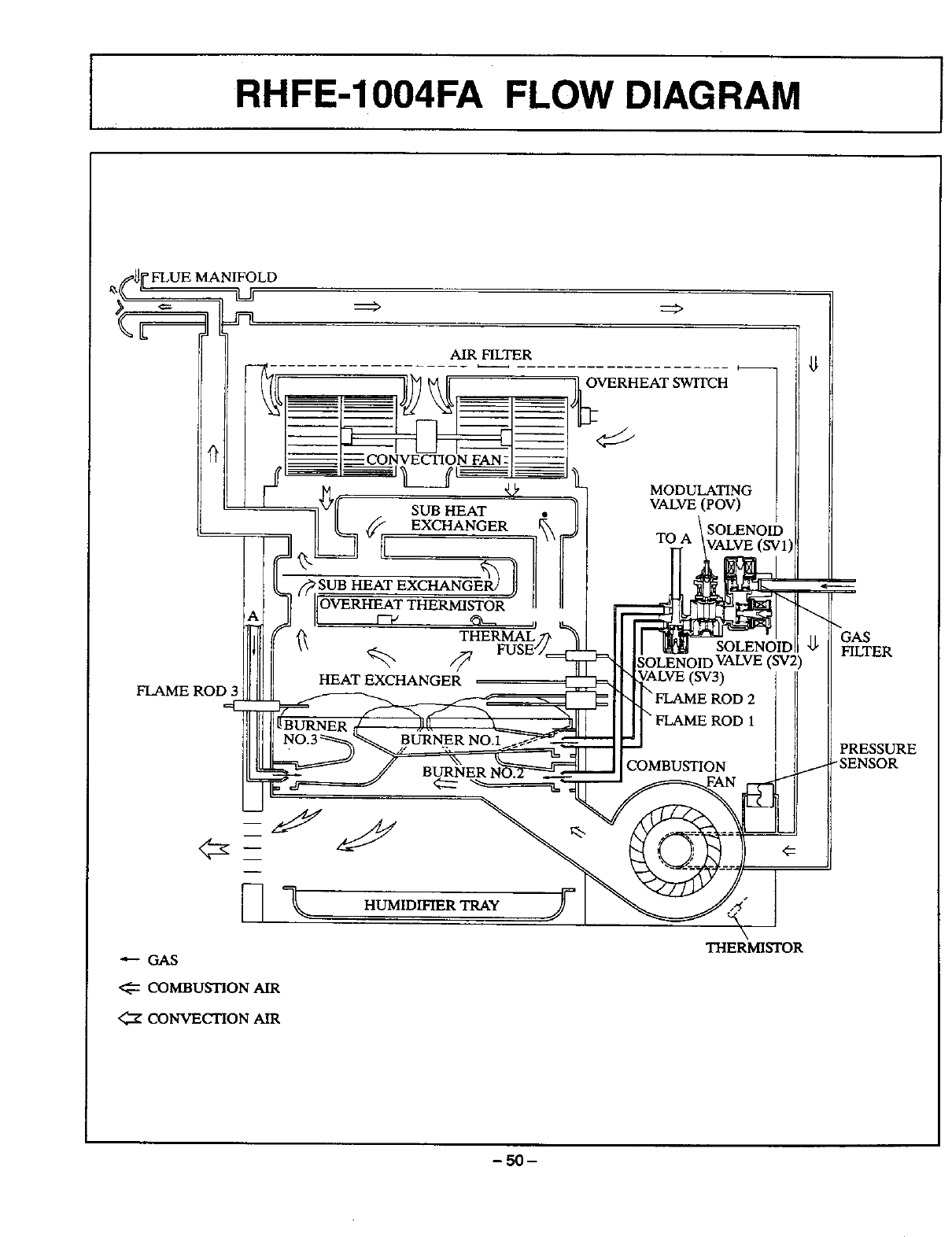
IRHFE-1004FA FLOW DIAGRAM
]1[_FLUE MANIFOLD
AIR HLTER
OVERHEAT SWITCH
FLAME ROD
_MODULATING
SUB HEAT VALVE (POV)
SOLENOID
TO (SV]
OLENOID VALVE (SV2)
\ FLAME ROD 1
I--1\ ._.,o_gT_,,
---- GAS
COMBUSTION AIR
<_X CONVECTION AIR
COMBUSTION
HLTER
PRESSURE
/-SENSOR
THERMISTOR
-50-
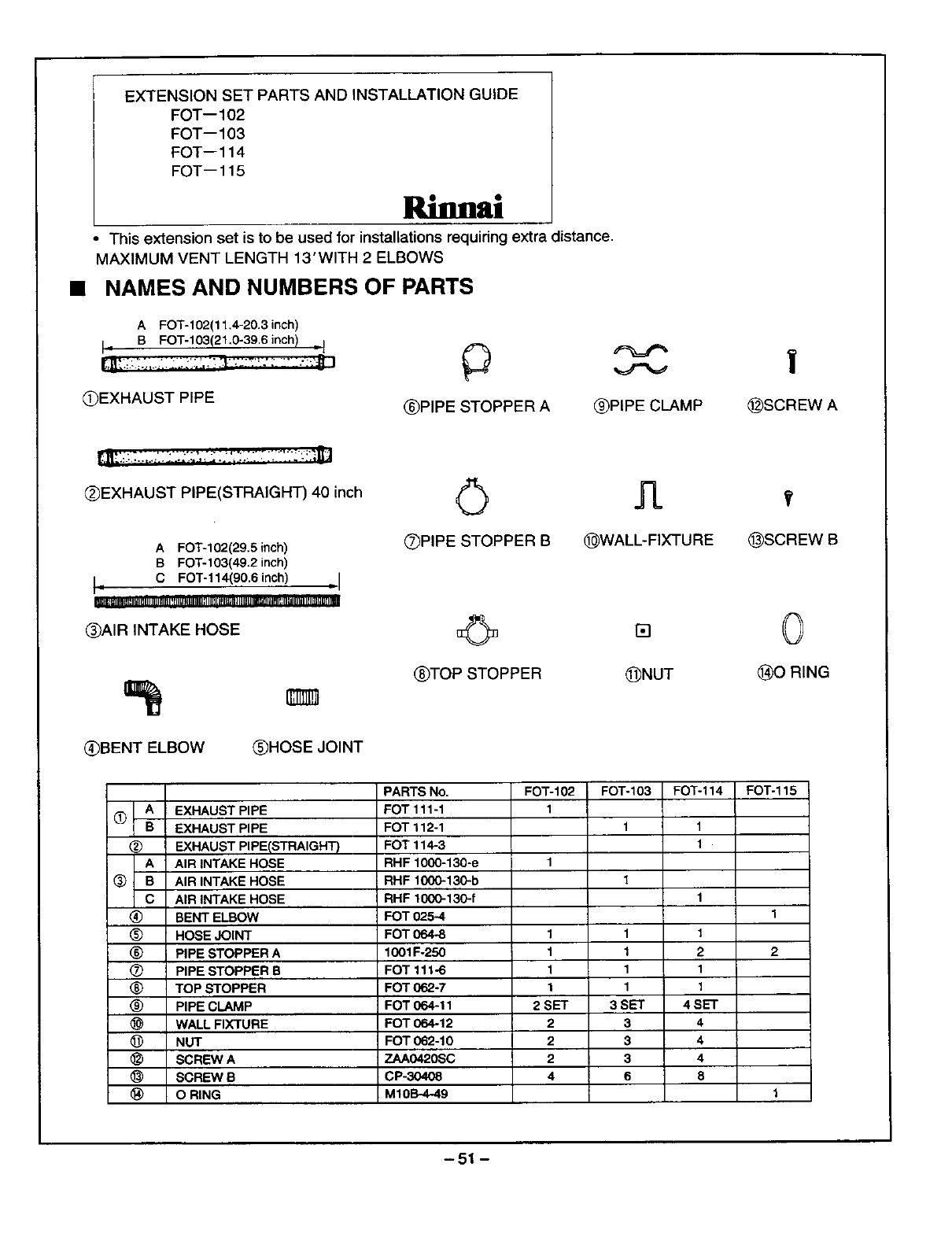
EXTENSION SET PARTS AND INSTALLATION GUIDE
FOT--102
FOT-- 103
FOT--114
FOT--115
llU si
This extension set is to be used for installations requiring extra distance.
MAXIMUM VENT LENGTH 13' WITH 2 ELBOWS
NAMES AND NUMBERS OF PARTS
A FOT-102(11.4-20.3 inch)
I • B FOT-103(21.0-39.6 inch) ,1
(_EXHAUST PIPE
_) _%==_
(_PIPE STOPPER A _PIPE CLAMP
(_EXHAUST PIPE(STRAIGHT) 40 inch
A FOT-102(29.5 inch)
B FOT-103(49.2 inch)
i= CFOT-114(906 inch) ,I
i
EKIRE_III_IIt_IIIII]I_IIIIIIIrlI!rlILI Jl_Jlll[I;llll][]m_l Jl IIIImt JfllliHl_:__11 ilUglJ[llml
(_)AIR INTAKE HOSE
|
_SCREW A
(_)BENT ELBOW _HOSE JOINT
QPIPE STOPPER B (_WALL-FIXTURE _SCREW B
_TOP STOPPER (_NUT (_X_)RING
PARTS No FOT-102 FOT-103 FOT-114 FOT-115
(X) __A EXHAUST PIPE FOT 111-1 1
_B EXHAUST PIPE FOT 112-1 1 1
(_ EXHAUST PIPEISTRAIGHT )FOT 114-3 1
A AIR INTAKE HOSE RHF 1000-130-e 1
(_ B AIR INTAKE HOSE RHF 1000-130-b 1
C AIR INTAKE HOSE RHF 1000-130-f 1
(_) BENT ELBOW FOT 025-4 1
_) HOSE JOINT FOT 0648 1 1 1
(_ PIPE STOPPER A 1001F-250 1 1 2 2
(_ PIPE STOPPER B FOT 111.6 1 1 1
_) TOP _rOPPER FOT 062-7 1 1 1
(_) PIPE CLAMP FOT 064-11 2SET 3SET 4SET
WALL FIXTURE FOT 064-12 2 3 4
_) NUT FOT 062-10 2 3 4
SCREW A ZAA0420SC 2 3 4
SCREW B CP-30408 4 6 8
O RING M10B-4-49 1
-51 -
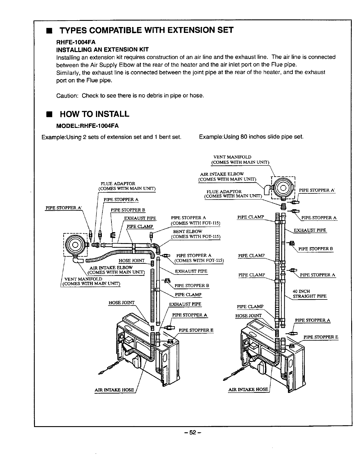
• TYPES COMPATIBLE WITH EXTENSION SET
RHFE-1004FA
INSTALLING AN EXTENSION KIT
Installing an extension kit requires construction of an air line and the exhaust line. The air line is connected
between the Air Suppty Elbow at the rear of the heater and the air inlet port on the Flue pipe.
Similarly, the exhaust line is connected between the joint pipe at the rear of the heater, and the exhaust
port on the Flue pipe.
Caution: Check to see there is no debris in pipe or hose.
•HOW TO INSTALL
MODEL:RHFE-1004FA
Example:Using 2 sets of extension set and 1bent set. Example:Using 80 inches slide pipe set.
PIPE STOPPER A'
FLUE ADAPTOR
(COMES WITH MAIN UNIT)
PIPE STOPPER A
PIPE STOPPER B
EXHAUST PIPE
PIPE CLAMP
VENT MANIFOLD
(COMES WITH MAIN UNIT)
AIR INTAKE ELBOW
(COMES WITH MAIN UNIT) \
FLUE ADAPTOR
(COMES WITH MAIN UNIT
PIPE STOPPER A
(COMES WITH POT- I15)
BENT ELBOW
(COMES W1TH FOT-115)
PIPE CLAMP
PIPE CLAMP
PIPE CLAMP
(
PIPE STOPPER A"
PIPE STOPPER A
-_PIPE STOPPER B
"_ PIPE STOPPER A
HOSE JOINT _UST PIPE
PIPE STOPPER A
PIPE STOPPER E
PIPE CLAMP
HOSE JOINT _
40 INCH
STRAIGHT PIPE
PIPE STOPPER A
PIPE STOPPER E
AIR INTAKE HOSE AIR INTAKE HOSE
- 52 -
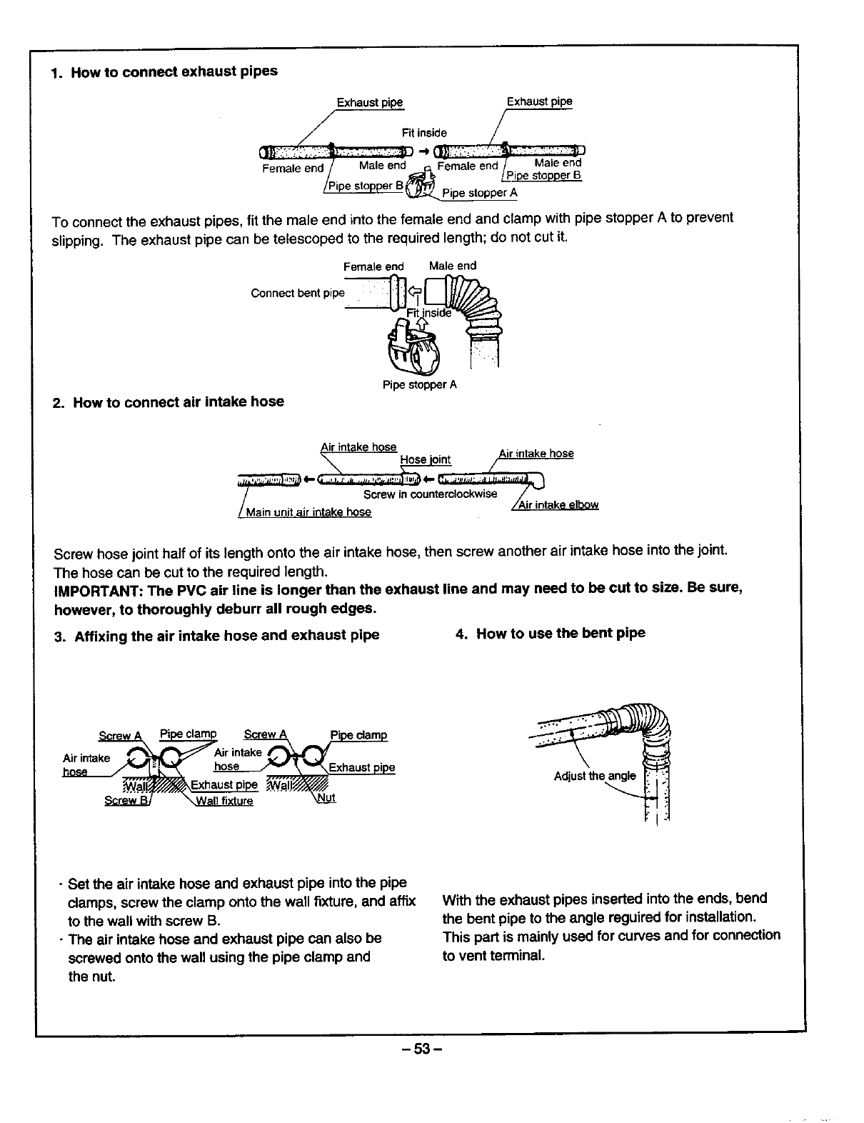
1. How to connect exhaust pipes
Exhaust pipe Exhaust pipe
fFit inside
Female end /Male enc]_ Female end /. Male end
/_ _ /P_pe stopper B
_.._topper A
To connect the exhaust pipes, fit the male end into the female end and clamp with pipe stopper A to prevent
slipping. The exhaust pipe can be telescoped to the required length; do not cut it.
Female end Male end
Connect bent pipe
2. How to connect air intake hose
Pipe stopper A
"7_ Screw in counterclockwise J_'_
/....... /Air intake elbow
/Main unit a=rretake hose
Screw hose joint half of its length onto the air intake hose, then screw another air intake hose into the joint.
The hose can be cut to the required length.
IMPORTANT: The PVC air line is longer than the exhaust line and may need to be cut to size. Be sure,
however, to thoroughly deburr all rough edges.
3. Affixing the air intake hose and exhaust pipe 4. How to use the bent pipe
Air intake _Air intake _ l_'
__Exhaust pipe Adjustthe_
• Set the air intake hose and exhaust pipe into the pipe
clamps, screw the clamp onto the wall fixture, and affix
to the wall with screw B.
• The air intake hose and exhaust pipe can also be
screwed onto the wall using the pipe clamp and
the nut.
With the exhaust pipes inserted into the ends, bend
the bent pipe to the angle reguired for installation.
This part is mainly used for curves and for connection
to vent terminal.
-53-
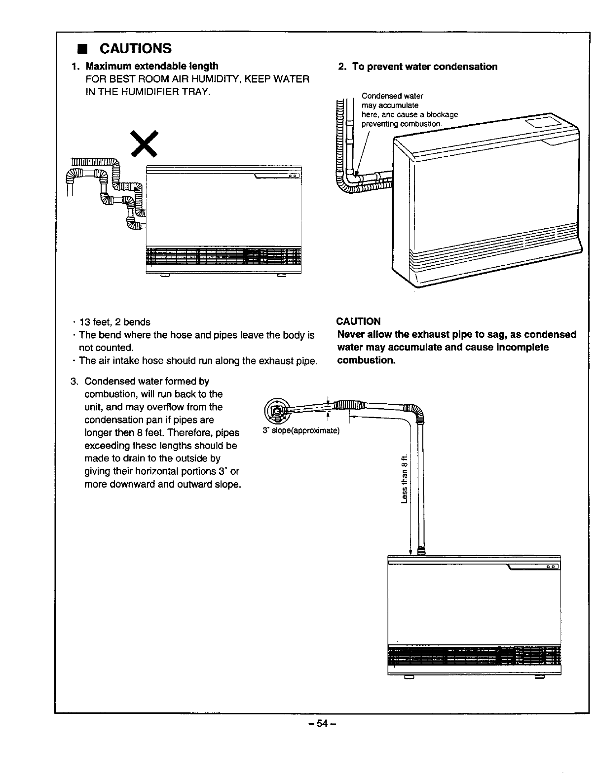
• CAUTIONS
1. Maximum extendable length
FOR BEST ROOM AIR HUMIDITY, KEEP WATER
IN THE HUMIDIFIER TRAY.
X
2. To prevent water condensation
Condensed water
_1 ! may accumulate
LI here, a?d cause a t_lockage
•13 feet, 2bends
•The bend where the hose and pipes leave the body is
not counted.
•The air intake hose should run along the exhaust pipe.
3. Condensed water formed by
combustion, will run back to the
unit, and may overflow from the
condensation pan if pipes are
longer then 8 feet. Therefore, pipes
exceeding these lengths should be
made to drain to the outside by
giving their horizontal portions 3" or
more downward and outward slope.
3" slope(approximate)
CAUTION
Never allow the exhaust pipe to sag, as condensed
water may accumulate and cause incomplete
combustion.
-54-

4. Wherever the air intake hose and exhaust pipe
run sideways, try to have the exhaust pipe on
top (to prevent the air intake hose from sagging
onto the exhaust pipe).
Exhaust pipe
Exhaust pipe
QUALIFIED INSTALLING AGENCY
The installation must conform to local codes, in the
absence of local codes, the installation must
conform with American National Standard (National
Fuel Gas Code) known as NFPA 54 and ANSI
Z223.1.1996.
Available from the American National Standards
Institute, Inc., 1430 Broadway, New York, N.Y. 10018
or from the National Fire Protection Association,
470 Atlantic Avenue, Boston, Mass. 02210.
Air intake hose
Air intake hose
-55-
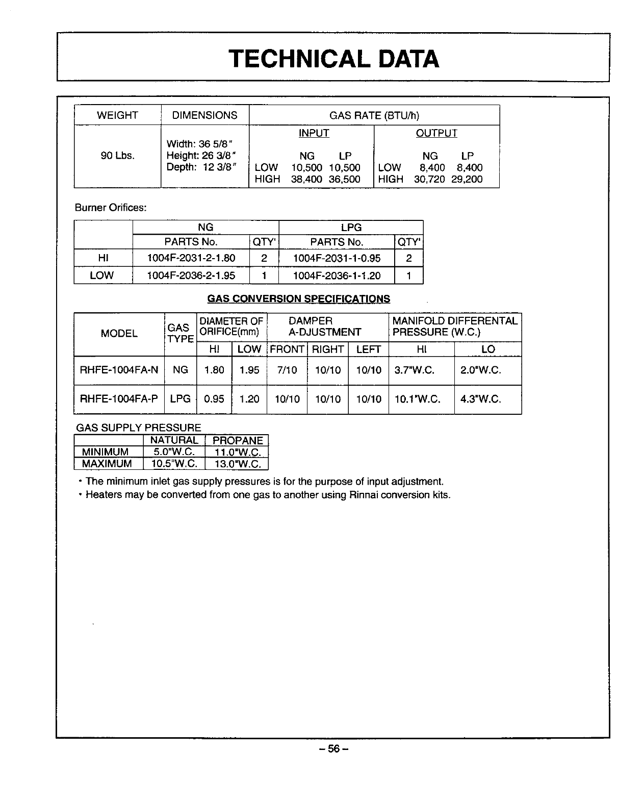
TECHNICAL DATA
WEIGHT GAS RATE (BTU/h)
INPUT OUTPUT
90 Lbs.
DIMENSIONS
Width: 36 5/8"
Height: 26 3/8"
Depth: 12 3/8"
NG LP NG LP
LOW 10,500 10,500 LOW 8,400 8,400
HIGH 38,400 36,500 HIGH 30,720 29,200
Burner Orifices:
HI
LOW
NG LPG
PARTS No. QTY' PARTS No. QTY'
1004F-2031-2-1.80 2 1004F-2031-1-0.95 2
1004F-2036-2-1.95 1 1004F-2036-1-1.20 1
GAS CONVERSION SPECIFICATIONS
MODEL
RHFE-1004FA-N
RHFE-1004FA-P
, DIAMETER OF
iGAS ORIFICE(mm)
TYPE HI LOW
NG 1.8O 1.95
LPG 0.95 1.20
DAMPER
A-DJUSTMENT
FRONT RIGHT LEFT
7/10 10/10 10/10
10/10 10/10 10/10
MANIFOLD DIFFERENTAL
PRESSURE (W.C.)
HI LO
3.7"W.C. 2.0"W.C.
10.1"W.C. 4.3"W.C.
GAS SUPPLYPRESSURE
NATURAL
MINIMUM 5.0"W.C.
MAXIMUM 10.5"W.C.
PROPANE
11.0"W.C.
13.0"W.C.
•The minimum inlet gas supply pressures is for the purpose of input adjustment.
• Heaters may be converted from one gas to another using Rinnai conversion kits.
-56-
-57-
NAME TITLE
COMPANY
ADDRESS
CITY STATE ZIP
PHONE NUMBER
I1[111
BUSINESS REPLY MAIL
RRST CLASS PERMITNO.271 LAGRANGE,GA
_WiLL BEPAIDBY _
Rinnai America Corp.
1662 Lukken Industrial Drive West
LaGrange GA 30240-9867
I,,11,11,,,,,I,1,1,,111,,,I,1,,I,,I,,11,,I,,,I,,,111
NO POSTAGE
NECESSARY
IF MAILED
IN THE
UNITED STATES
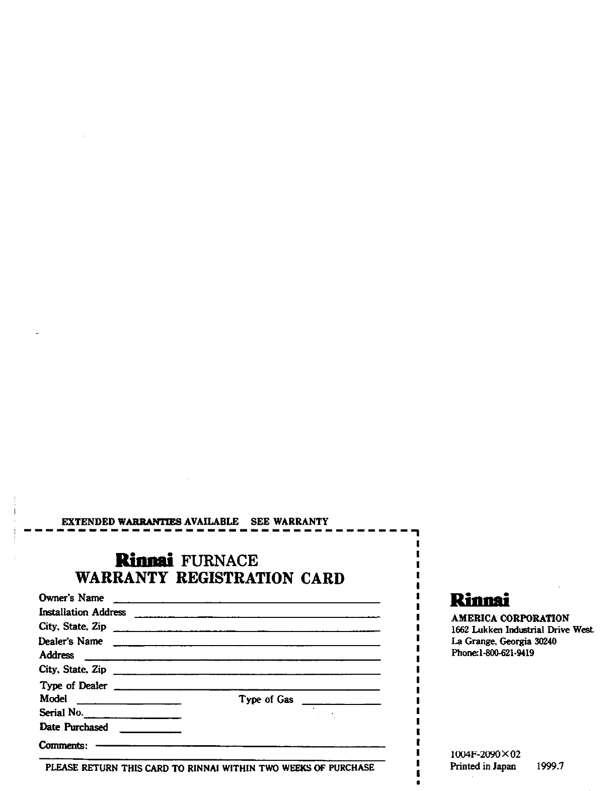
EXTENDED WARRANTIES AVAILABLE SEE WARRANTY
FURNACE
WARRANTY REGISTRATION CARD
Owner's Name
Installation Add_ss
City, State, Zip
Dealer's Name
Address
City. State. Zip
Type of Dealer
Model
Serial No.
Date Purchased
Comments:
Type of Gas
PLEASE RETURN THIS CARD TO RINNAI WITHIN TWO WEEKS OF PURCHASE
Rimud
AMERICA CORPORATION
1662 Lukken Industrial Drive West
La Grange, Georgia 30240
Phone:l-800-621.9419
1004F-2090 × 02
Printed in Japan 1999.7
