RM COSTRUZIONI ELETTRONICHE Srl BLA600 AMPLIFIER User Manual
RM COSTRUZIONI ELETTRONICHE Snc di Marchioni Davide e Daniele AMPLIFIER
User Manual
Solid State HF & 6m 500W Linear Power
Amplifier
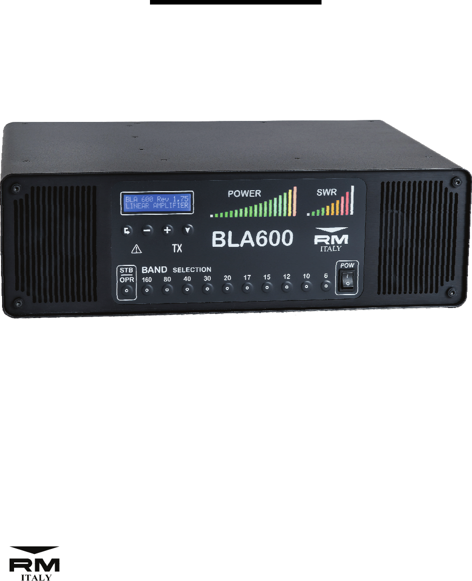
BLA600
User Manual
http://www.rmitaly.com
Costruzioni Elettroniche
Rev 1.0 June 2017
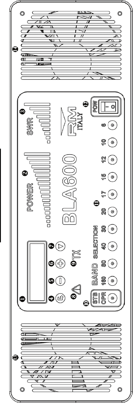
1. LCD Display (2x16 character)
2. LED Output Power Bargraph
3. LED VSWR Level Bargraph
4. Enter key
5. Data key ’-’
6. Data key ’+’
7. Navigate key
BLA600 Front Panel
8. LED Warning / Protection
9. LED TX Indicator
10. ‘Standby’ / ‘Operate’ Key
11. Manual Band Select Keys
12. AC Mains ‘ON’ / ‘OFF’ Switch
13. RF Deck Cooling Intake
14. LPF Board / PSU Cooling Intake
2
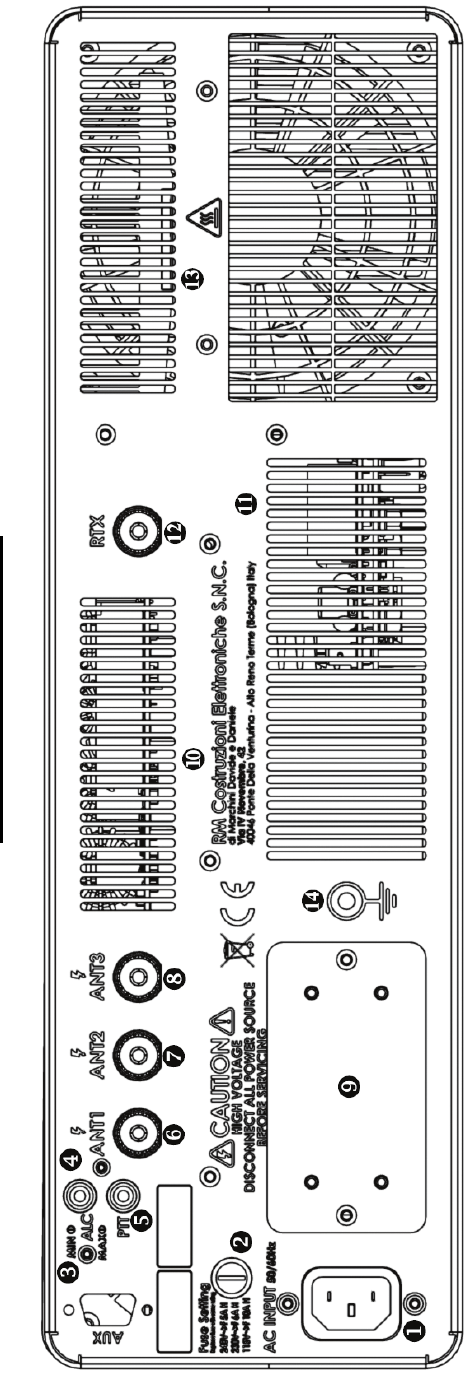
BLA600 Rear Panel
1. AC Mains Inlet Socket
2. AC Line Fuse
3. ALC Min / Max Adjustment
4. ALC Output Connector (Phono / RCA Type)
5. PTT Input Connector (Phono / RCA Type)
6. Antenna 1 Output Connector (SO239)
7. Antenna 2 Output Connector (SO239)
8. Antenna 3 Output Connector (SO239)
9. AC Input Voltage Selection
10. Exhaust Grille LPF PCB
11. Exhaust Grille PSU
12. RTX Input Connector (SO239)
13. RF Deck Exhaust Grille
14. RF Ground Stud M5
3

Introduction
The RM Italy BLA600 is a fully automatic HF & 6m 500W solid state
linear amplifier suitable for seamless integration with all modern trans-
ceivers. The BLA600 utilises the rugged NXP / Freescale
MRF6VP5600H 50V device for high power and high reliability operation.
It is suitable for the diverse array of modern modulation modes. The
BLA600 is fully automatic, with instant band changes and features a fast,
reliable and silent PIN diode RTX switching, making it ideal also for CW
QSK operation. The BLA600 has 3 antenna outputs easily configurable
on a per band basis as per the user requirement. The RF deck is supplied
by a heavy duty linear power supply, with 115/230 and 240 volt AC input
options, but utilises an efficient active bridge rectifier and high grade fil-
ter capacitors to provide the amplifier with a very low noise and robust
50V DC supply. The RF deck has a large heat sink and copper heat
spreader which provides a very efficient cooling system with separate
fans for the RF deck and LPF board / power supply for high duty cycle
operation. Internally all modules are mounted in a very robust and well
screened enclosure. The BLA600 features Dual MCU control and an ex-
tensive array of protection circuits which look after the amplifier with
rapid reaction time, VSWR, I/P Power, I/P Frequency, 3 Temperature sen-
sors, (Transistor / Heat sink and PSU), Drain voltage / Drain current, HV
PIN supply, are all continuously monitored.
DISTRIBUTED BY:
4

Contents
1. Front Panel Description....................................................... 2
2. Rear Panel Description......................................................... 3
3. Introduction.......................................................................... 4
4. Warning................................................................................ 6
5. Unpacking............................................................................ 7
6. Installation............................................................................ 7
7. Antenna Output Selection.................................................... 9
8. Operation.............................................................................. 10
9. Modulation Modes............................................................... 13
10. Menu.................................................................................... 13
1: ALC....................................................................... 14
2: TEMP..................................................................... 16
3: BRIGHTNESS.......................................................... 16
4: CONTRAST............................................................. 17
5: CW QSK................................................................. 17
6: STANDBY (STB) PARAMETERS.................................. 18
7: OPERATE (OP) PARAMETERS.................................... 18
8: DEFAULT................................................................ 19
9: ESC .................................................................... 19
10. Protection............................................................................. 20
Start Up Errors........................................................ 20
Operational Errors................................................... 21
11. Grounding............................................................................. 23
12. Warranty................................................................................ 25
13. Specifications....................................................................... 26
5

4. Warning!
Before connecting this product to the AC supply verify that the model supplied is
configured for the correct line voltage be it 115Vac 230Vac or 240Vac. Failure to do
this may cause extensive damage to the amplifier.
Dangerous voltages are present inside this product, AC Line Voltage 230/240Vac,
HV 380Vdc and RF voltages. There are no user serviceable parts inside and the
cover must not be removed by the user under any circumstances especially whilst
the AC power cord is connected. Service to this product must only be carried out by
qualified service technicians.
This product is capable of producing high levels of RF energy so it is assumed that
the user be familiar and qualified to use this apparatus before any connections are
made to it. Making sure and being confident with any equipment connected to the
amplifier is suitably rated for the output power. Antennas, Baluns, Feeders, ATU’s
must all be capable of handling 500W continuously at the frequency of operation.
The amplifier must be connected to the station RF ground via the ground stud on the
rear panel
h, which should be properly implemented, by means of a short and low
impedance connection usually by means of a heavy copper strap. This will decrease
noise problems in reception and eliminate the possibility of high RF voltages
appearing on the chassis of the amplifier and other metallic equipment in the station
that the operator may come into contact with. This can be due to unbalanced
antennas or static build up. (Do not use gas supply tubing or water supply tubing as
an RF ground!!). See Section Grounding.
Antennas connected to this amplifier should be mounted well away from the
possibility of human or animal contact to avoid the risk of electrical shock and RF
exposure.
Keep fluids well away from the amplifier and do not use the amplifier if it is subject
to direct sunlight for a long period of time.
If during operation any abnormal noise / odour is noticed, switch off the amplifier
immediately, check all connections to the amplfier and if necessary return the
amplifier to an authorised service centre for testing.
Do not overdrive the amplfier, 40W is the absolute maximum input power required
only on 160 and 6m. All other bands require a maximum of 20W to realise full
output power.
In operation the exhaust area of the heatsink g will become hot, do not touch this
area during or immediately after operating the amplifier.
6

5. Unpacking:
Inspect the shipping carton for signs of damage during shipping and then carefully
remove the amplifier from the packaging. If any damage is present note in as much
detail as possible and take a photograph of the damage to send immediately to the
supplier. Retain all of the original packaging as this must be used if the amplifier is
to be returned to the supplier. Check all output connectors on the rear panel. If the
amplifier has been in a cold environment for a prolonged period of time before being
brought into a warmer area allow a suitable period of time before the amplifier is
connected to the AC mains supply to allow any internal condensation to dissipate.
6. Installation:
Position:
The amplifier should be installed in a cool, dry not excessively dusty area that has
sufficient space surrounding the amplifier to allow good ventilation. As the intake
for the cooling fans is from the front panel this should not present any problems but
both intakes should not be obscured in any way. Do not use the amplifier if it is in
direct sunlight for long periods. The rear panel of the amplifier should be no closer
than 15cm from a wall to allow the exhaust air to freely exit the amplifier for
optimum cooling efficiency.
As the amplifier is quite heavy make sure that the supporting structure is capable of
supporting the weight.
Connection:
The BLA600 requires the following connections in order to function.
The output of the transceiver should be connected to the RTX f input on the rear
panel with a suitable 50 Ohm patch cable terminated in PL259 UHF connectors. The
length is not critical but should be kept as short as practically possible.
The BLA600 has 3 antenna outputs `ab that may be configured on a per band basis
to the users requirements see section 7. Default from the factory Ant:1 ` is active
for all bands. The output from the antenna socket should be connected to a suitably
rated 50 Ohm cable, minimum rating 500W continuous at the highest used
frequency, (52 / 54MHz), terminated in a PL259 UHF connector. (We recommend a
50 Ohm low loss 10mm cable for the output side such as RG213 spec. or better).
This may be connected directly to a suitable resonant antenna of 50 Ohms resistive
input impedance which must be continuously rated at least to the maximum output
of the amplifier.
7
If a non resonant antenna is used together with an Antenna Matching Unit, (AMU/
ATU/Tuner), then the output of the amplifier should be connected first to the input
of an SWR / Power meter, (if not integrated with the ATU), then the output of the
SWR/Power meter to the input of the antenna tuner and then finally the antenna.
The ATU also needs to be suitably rated for the power output of the amplifier.
Nearly all ATU’s are rated at maximum power only under tuned conditions. If
the ATU also has an internal BALUN for connection to balanced feeder make sure
that this too is rated to at least the maximum power of the amplifier.
Note: If your transceiver has a built in Antenna Tuner this must be disabled if
the amplifier is connected as it can no longer be used to tune the antenna. In
TX input to the amplifier is 50 ohms.
The BLA600 also requires a PTT input from the transceiver to switch between RX
and TX. Without this input the amplifier cannot be used. Look in the manual of your
transceiver for how to connect to the PTT Output. (Do not confuse this with the PTT
input on some radios, usually made available for a foot switch or separate PTT input
if the standard microphone PTT is not used). The PTT input
_is a close to ground
system which is compatible with all modern radios that use open collector or open
drain outputs, for further information consult the instruction manual for the
transceiver or your dealer on how to connect an external linear amplifier. The PTT
Input to the amplifier requires an RCA / Phono type plug. The cable should be
screened, length is not critical but should be as short as practically possible.
The RF ground post h on the rear panel should be securely connected to your station
RF ground with a suitable low inductance ground strap. The house Gas or Water
pipes should NEVER be used for this purpose. (Gas pipes for obvious reasons with
risk of explosion, water pipes as they do not necessarily provide a low impedance
path to ground and may well actually be isolated from ground if the house water
supply is from a plastic water pipe, they can also introduce a higher noise floor and
cause risk of electric shock to other uses of the water supply if not grounded). See
section on Grounding page 20 for further details.
The ALC
^may also optionally be connected, (See ALC menu for further details),
however the drive power for the BLA600 should be manually controlled on the
transceiver by the user to obtain the required output power from the amplifier.
8
7. Antenna Output Selection
The BLA600 has 3 user configurable antenna outputs. As supplied from the factory
the default antenna output is Ant:1 for all bands. Each band may be independently
configured to any one of the three outputs.
To change any particular band to different antenna output it is necessary to be in
‘Standby’ mode. First select the band by pressing the relevant band select key e.
Then select the required antenna output by using the ‘+’ ` or ‘-‘ _ keys under the
LCD display to select Ant:1, Ant:2 or Ant:3 To memorise the new selection press
and hold the ‘Navigate’ key a for 3 seconds. The antenna output number will begin
to flash and then after 3 seconds a beep will be heard confirming the saved selection.
Each time the same band is returned to the last memorised selection will be returned.
In ‘Standby’ mode pressing the band key of any band will display the currently
memorised Antenna output on the LCD display.
The antenna output may also be changed temporarily without saving the selection.
This can be useful in RX/TX if testing two different antennas for the same band.
Simply use the ‘+’ ` and ‘–’ _ keys to change the antenna output without saving
the selection. Again this must be done in ‘Standby’ mode but after the change has
been made it is possible to change to ‘Operate’ mode and use the new selection. If a
new band is selected the non saved output will return to the default or last
memorised selection when that band is returned to.
9
The radio must be capable of about 40W to obtain full output on all bands.
Generally around 20W is sufficient for full output on the bands 80 to 10m). More
power is required on 160m and 6m for full output. Due to the accurate frequency
reading and high speed band switching of the BLA600 a CAT interface connection is
not required for automatic band change. A high speed PIN Diode switch is used so
the amplifier will switch back to bypass briefly whilst the Low Pass Filter relays
insert a different filter, so at no point are any relays hot switched thus avoiding
possible contact damage from arching and presenting the amplifier briefly with an
open circuit load. The amplifier is supplied with the default antenna output as
antenna 1
`for all bands, so we suggest that for initial testing this output should
not be changed. We also recommend that the first test should be carried out with the
output connected directly to a power meter / dummy load whist familiarity is gained
with the operation of the amplifier.
8. Operation:
With the amplifier in ‘Standby’ or connected in line but physically switched off a
maximum of 100W may be used. With the amplifier switched off antenna 1
`is the
active output. With the amplifier switched on but in ‘Standby’ the output will be
determined by the frequency of transmission and the programmed Antenna output 1,
2 or 3 for that frequency. As shipped from the factory all bands are set to ANT 1
output.
For the first time we recommend a dummy load be connected to the output whilst
the user gains familiarity with the operation of the BLA600. This with the default
factory setting should be connected to ANT 1 output `. A suitable power meter may
also be connected between the two. The power should be reduced to minimum on
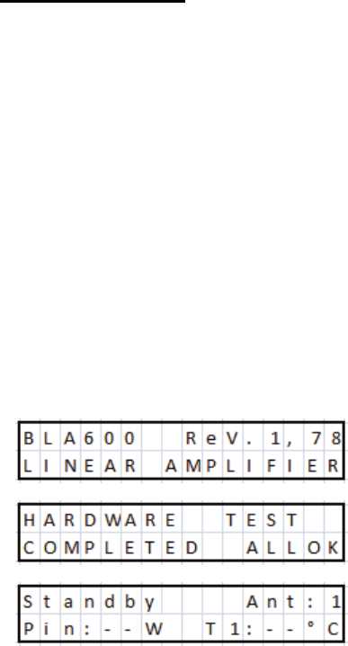
the transceiver, (see your user manual). Switch on the amplifier and wait for the self
test procedure to complete.
After this has taken place the amplifier will be ‘Standby’ mode. A test transmission
can now be made to ensure that there is no problem with any of the connections.
During this time the amplifier will read the transmit frequency and automatically
change to the correct Low Pass Filter, which will be indicated on the front panel by
illuminating the relevant band indicator e. (The correct band filter may also be
10
selected manually prior to transmission, but not essential).
Manual band filter selection can only be made when the amplifier is in ‘Standby’
mode. When the Amplifier is switched to ‘OPR’ (Operate) no manual band change
can be made, the amplifier will automatically switch bands as soon as the radio
begins to transmit after a band change.
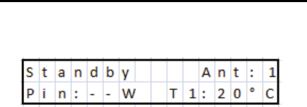
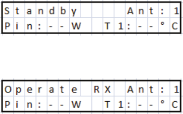
Default from the factory the standard ‘Standby’ parameters are Pin (Input Power)
and T1 (Transistor temperature). Pin maybe used when adjusting the input power to
the amplifier, but for the first transmission we recommend that the transceiver power
be set to minimum output power. (Pin in Standby will only be accurate if the output
load is 50 Ohms resistive).
Now switch to ‘OPR’ Operate, by pressing the ‘STB / OPR button d
.
Begin a transmission and you will see that the amplifier is functional, The TX LED
c will illuminate to indicate the PTT input is working and that the amplifier has
switched to transmit. If there are no alarms adjust the drive power until a maximum
of 500W is displayed on the power meter. This is best carried out either in a constant
carrier mode, CW or FM to provide a constant output level. You can then see what
input power is required to drive the amplifier to 500W. So long as you are operating
into a 50 ohm resistive load / antenna there is no problem to remain in TX whilst
doing this procedure for some time, if your dummy load is suitably rated. (if doing
this into a radiating antenna, transmissions should be made as brief as possible to
avoid unnecessary interference).
The amplifier on most bands is capable of more than 500W output, however 500W
is the point 1dB compression, driving the amplifier harder will cause increasing
compression with the increase in distortion in linear modes such as SSB etc. The
extra power in the output will make little difference at the receiving station and may
even reduce the quality of the signal if the amplifier is being driven too hard into
compression.
(As an example let’s look at the difference between 500W and 560W output.
Assuming 20W drive for both conditions, (in reality more power would be required
for the higher output, so the difference would be lower, but this will suffice to
explain the concept). 10*Log(10) 500/20 =13.98dB Gain. 10*Log(10) 560/20 =
14.47dB gain.
11
The difference between the two values is approximately 0.5dB. Now consider that 1
‘S’ Point on your receiver is usually approximately 6dB you can immediately see
that 0.5dB difference really will be unnoticeable on his ‘S’ meter, if the amplifier is
now well into compression the linearity is lower and the distortion will increase
probably making your signal actually slightly less intelligible).
The amplifier is fully protected for input overdrive even accidental 100W on the
input has not been found to cause damage as the protection is extremely quick but
this should obviously be avoided.
*Important note regarding ATU’s and non resonant antennas*
It is very important to understand when using a non resonant antenna in
conjunction with an Antenna Matching Unit (ATU, Tuner etc.), that the
antenna is only tuned under low power, ie with the amplifier in Standby.
Usually the ATU requires only a few watts <10W in order to tune the antenna to
resonance. If you find that that when the amplifier is outputting high power
that there is a significant difference in the VSWR this usually means that there
is a problem. Either that the ATU cannot support the increased power, or
maybe the Balun if used , is not sufficiently rated, or a problem with the
antenna itself not being able to support high power. Antennas that have
matching networks or baluns at the feed point or trapped antennas where
maybe an ATU is used to cover both CW and SSB sections of the band. Make
sure that these components are rated for the power being used. Sudden
increases in VSWR can also indicate arcing on variable capacitors or
component failure. Special attention must also be given to Automatic ATU’s.
These must ABSOLUTELY not be used to tune the antenna at high power,
(with the amplifier in ‘Operate’). As generally they use relays to switch between
banks of fixed inductors and capacitors, at high power the relays can be
damaged almost immediately if they have break before make contacts. Also
depending on the tuning algorithm used they can present very high / low
impedances to the internal components that may cause voltages and current
beyond safe limits. Auto tuners should be disabled such that another tuning
cycle cannot be made during TX periods at high power, after the initial low
power tuning. It is of course possible to make a final adjustment manually so
long as the adjustments are small. The BLA600 is protected against high
VSWR loads but it is very bad practice to tune the antenna at high power and
there is always the risk of damage to both the amplifier and ATU as well as
creating unneccessary interference on the bands.
12

9. Modulation Modes:
The BLA600 can be used in any narrow band mode of transmission. SSB/AM/FM/
CW and Data Modes as it is supplied from the factory. For all modes the amplifier
does not require any adjustment. As the RTX switching is done with a solid state
PIN Diode switch the time taken to switch state from RX to TX and TX to RX is
very short, (in the order of a few of milliseconds). However we have implemented a
mode specifically for those who require the minimum RTX switching time possible
for true QSK operation with the requirement to listen for signals between single
‘dits’ sent at high speed. Obviously a suitable transceiver is also required as the
switching time of the transceiver is often a limiting factor especially if it utilises
relay RTX switching.
The only difference between this feature and standard is that there is no display of
the two chosen parameters on the LCD during the transmission cycle, E.G. Drain
voltage and Heatsink temperature etc. However the amplifier is still monitoring all
of these parameters in background and nothing changes regarding protection of the
amplifier. See menu 5:CW QSK for further details.
10. Menu:
To enter into the menu system the BLA600 must be in ‘Standby’ mode. It is not
possible to enter the menu when in ‘Operate’ mode.
To enter the menu system press the ‘Enter’ key ^
Press the ‘Navigate’ key a to cycle through the menu options, continually pressing
the ‘Navigate’ key will eventually cycle back around to the first menu and repeat.
To exit the menu system, use the ‘Navigate’ key a to menu ‘8:Esc’ and press the
‘Enter’ key ^, or a single press of the ‘Standby’ / ‘Operate’ key d to return to
‘Standby’ mode or automatically exit after 10 seconds without any further key press.
13
Menu List
1:ALC
2:Temp
3:Brightness
4:Contrast
5:CW QSK
6:STB Parameters
7:OP Parameters
8:Default
9:Esc
1: ALC
The BLA600 has the optional ALC output for connection to the transceiver that can
be utilised as an additional level of protection. It should not however be used as a
primary means of adjusting the transceiver drive power. (Doing so can create
splatter and increase Intermodulation Distortion). ALC action will also depend on
the transceiver and in many cases the ALC circuit is slow reacting and will allow
many cycles of RF to pass before the ALC circuit acts to reduce the output power of
the transceiver. The ALC output is adjustable using the ALC menu and has a 0 to –
10V range, that is suitable for all modern transceivers. If using the ALC menu make
sure that the BLA600 ALC Output on the rear panel ^ is connected to the radios
ALC input. See your radios instruction manual for further details.
Adjusting the ALC level is a one time operation and when the adjustment is made
the amplifier is in Bypass and is not amplifying the signal. However to reduce
unnecessary interference we recommend that this be carried out with the output
connected to a dummy load.
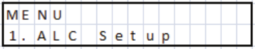
Select menu ‘1: ALC Setup’ with the ‘Navigate’ key a, press the ‘Enter’ key ^ to
access the menu.
The BLA600 has two adjustments for the ALC . Max Power and No Power. The
Transceiver drive power should first be adjusted manually as explained in section 7
‘Operation’. It is important to make this adjustment before setting the ALC. Select
the band that requires the most input drive from the transceiver either 160 or 6m.
14
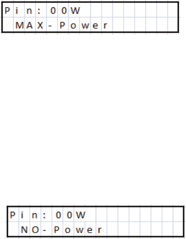
Press the ‘Enter’ key ^:
Adjustment of Max Power.
Adjust the ALC ‘MAX’ trimmer on the rear panel in TX until the transceiver power
just starts to reduce. At this point readjust the ‘MAX’ trimmer in the opposite
direction to just above the point where the power starts to fall, so that the output
power is not affected.
Press ‘Enter’
.
^
Now adjust the ALC ’MIN’ trimmer on the rear panel until there is no output from
the transceiver.
This sets the maximum ALC output voltage from the amplifier under fault
conditions, which will be used to reduce the input power to 0W.
When the power has been set to 0W Press ‘Enter’ .
^The ALC is now set and you
will be returned to the menu list. You can now continue within the menu or exit by
any one of the 3 ways explained previously.
ALC Max trimmer—Anticlockwise rotation as seen from the rear panel reduces
ALC voltage so increases power—Clockwise increases ALC output voltage and so
reduces power.
ALC Min trimmer—Clockwise rotation reduces ALC voltage and so increases
power—Anticlockwise increases ALC voltage and so reduces power.
15
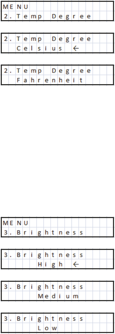
2: TEMP
Change the display temperature between degrees Fahrenheit and degrees Celsius.
Select menu ‘2: Temp’ with the ‘Navigate’ key a, press the ‘Enter’ key ^ to access
the menu. An arrow cursor will be shown at the end of the line indicating which is
the currently active setting. Use ‘+’
`and ‘-‘ _ keys to make the selection and
finally press the ‘Enter’ key
^to save the change, the arrow cursor will briefly
appear to indicate the change. At this point you will be returned to the menu list. You
can now continue within the menu or exit by any one of the 3 ways explained
previously.
3: BRIGHTNESS
Change the intensity of the LCD backlight, LED Power Meter, LED SWR Indicator.
There are 3 options, Low, Medium and High. Select menu ‘3:Brightness’ with the
‘Navigate’ key
athen press ‘Enter’ key ^ to access the menu. You can now use
the ‘+’ key ` to increase the brightness or the ‘-‘ key
_to decrease the brightness.
Press ‘Enter’ ^ to save the current selection and return to the menu list.
16
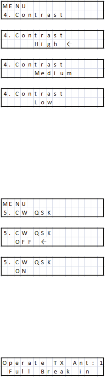
4: CONTRAST
Change the contrast of the LCD display. There are 3 options Low, Medium and
High. Select menu ‘4:Contrast’ with the ‘Navigate’ key a. Press ‘Enter’ key ^ to
access the menu. You can now use the ‘+’ key ` to increase the contrast and the ‘-‘
key _ to reduce the contrast. After selection, press the ‘Enter’ key ^ to save the
current selection and return to the menu list.
5: CW QSK
To minimise the RTX switching time for maximum performance in ‘Full Break In’
mode, especially if sending 25+WPM this menu should be activated. Use the
‘Navigate’ key a to select ‘5:CW QSK’ and then press the ‘Enter’ key ^ to access
the menu. Use ‘+’ ` or ‘-‘ _ keys to select ‘On’ or ‘Off’. Then press the ‘Enter’
key ^ to save the current selection and return to the menu list. When returning to
‘Operate’ mode the LCD display will have changed to:
17
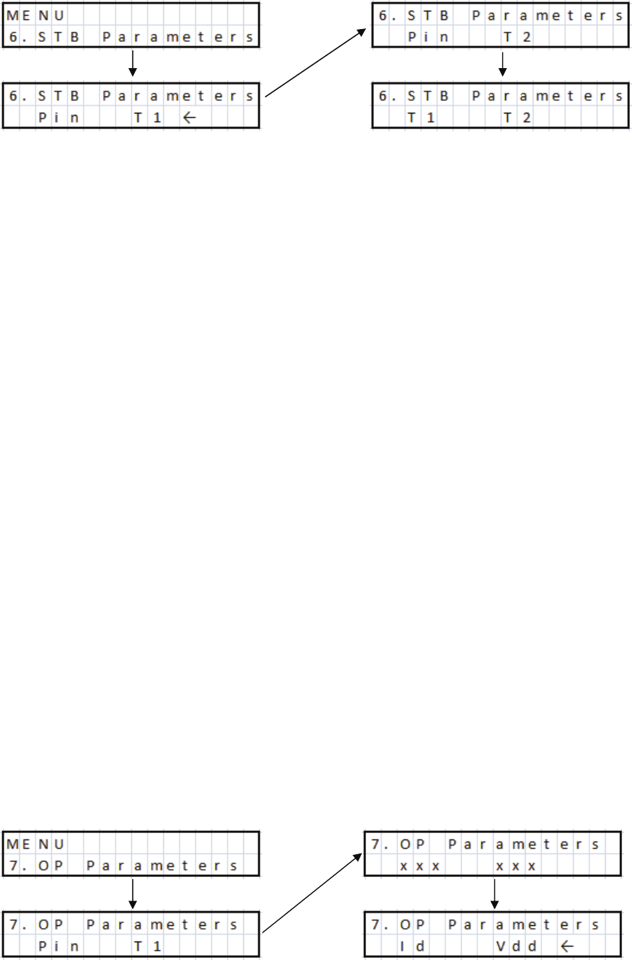
6: Standby Parameters
During RX it is possible to monitor two of the following parameters on the LCD
display:
Pin T1 (Input Power and T1, (T1- Temperature of Heatsink at transistor)
Pin T2 (Input Power and T2, (T2 Temperature of Heatsink at exhaust exit)
T2 T1 (T2-Temperature of Heatsink at exhaust and T1-Temperature of Heatsink
at the transistor)
Use the ‘Navigate’ key
ato select menu ‘6:RX Parameters’. Press the ‘Enter’ key
^ to access the menu and use the ‘+’ ` and ‘-‘ _ keys to choose from the above
three choices. Press the ‘Enter’ key ^ again to save the current selection and return
to the menu list.
7: Operate Parameters
During TX it is possible to monitor any of the following two Parameters on the LCD
display: (Not in QSK Full Break In Mode).
Pin T1 (Input Power and Heatsink Temperature at the transistor)
Pin T2 (Input Power and Heatsink Temperature at the exhaust exit)
Pin Vd (Input Power and Drain Voltage)
Pin Id (Input Power and Drain Current)
T2 T1 (Heatsink Temperature at the exhaust exit and Heatsink Temperature at the transistor)
Vd T1 (Drain Voltage and Heatsink Temperature at the transistor)
Id T1
(Drain Current and Heatsink Temperature at the transistor)
Vd T2 (Drain Voltage and Heatsink Temperature at the exhaust exit)
Id T2
(Drain Current and Heatsink Temperature at the exhaust exit)
Id Vd
(Drain Current and Drain Voltage)
18
Use the ‘Navigate’ key
ato select menu ‘7:TX Parameters’. Press the ‘Enter’ key
^to access the menu and use the ‘+’
`and ‘-‘ ` keys to choose from the above
ten choices. Press the ‘Enter’ key ^ again to save the current selection and return to
the menu list.
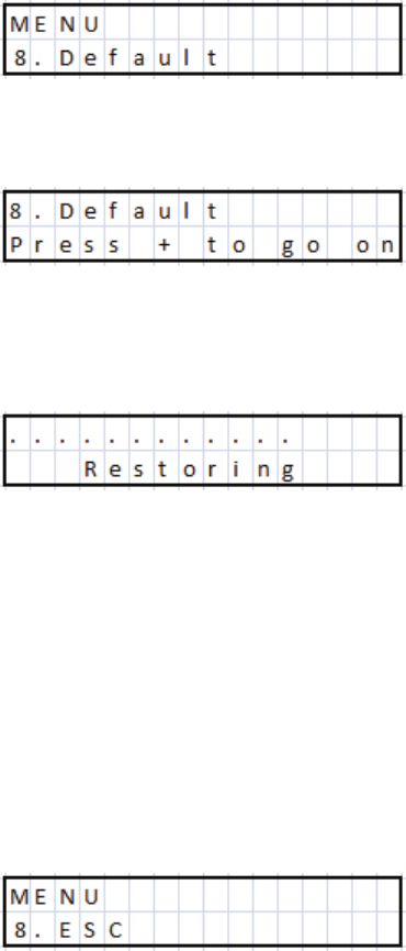
8: Default
This function allows the user to quickly return the amplifier to its factory settings.
All user modified parameters will be returned to default settings.
Use the ‘Navigate’ key a to select menu ‘8:Default’.
Press the ‘Enter’
^key to acess the menu
Then press the ‘+’ key
`to activate the process, and the following screen will be
displayed. This will take a few seconds to complete.
The amplifier will then reboot and return to ‘Standby’ mode.
9:Esc
Exit the menu list.
Use the ‘Navigate’ key a to select menu ‘8:ESC’. Press the ‘Enter’ key ^ to exit the
menu list and return to Standby.
19

The BLA600 makes a series of self tests during the start
up sequence. If any of the following errors occur refer to
the description below
11. Protection:
The BLA600 has a comprehensive and rapid reacting protection system. The
following parameters are continually monitored during operation. RF input
frequency, (within limits of operation bandwidth), RF drive level (40W 160m, 25W
all other bands). Forward and Reflected voltages, from which the VSWR is
calculated, (maximum VSWR 2.5-3:1). Drain voltage (Vd) both high and low limits,
Drain current Id, (Both software and hardware monitored), Transistor temperature,
Heatsink temperature, Power Supply temperature. PIN switch HV and control
signals and Cooling Fan speed.
Start Up Errors
During the start-up self test should any of the following errors occur refer to the
descripton below for explanation:
S1 Error with the cooling fans. Check for obstructions and reboot the amplifier. If
the problem persists consult your dealer.
S2 Control of (Vd) drain voltage, (above 48V). If this error occurs check that the
AC supply voltage is within normal limits.
S3 Control of (Vd) drain voltage, (below 70V). Again check that the AC supply
voltage is within normal limits.
S4 Control of (Vd) drain voltage , above 48V when transistor bias is tested.
S5 Control of transistor bias current above lower limit
PTT is active check radio is not in TX or PTT cable is not
damaged. Remove PTT connector from rear panel and retry.
Check that there is nothing obstructing the fans blades.
Pressing the ‘+’ key
`will allow the amplifier to function,
however we do not recommend this to be done. Reboot the
amplifier and try again. If the problem continues consult your
dealer.
20
S6 Control of transistor bias current below upper limit
S7 PIN Diode Switch standby mode
S8 PIN Diode Switch RX test
S9 PIN Diode Switch TX test
If any of the above errors continue to occur you should seek further advice from
your dealer.
Operational Errors
During normal operation if a fault occurs one of the following error messages will
be displayed.
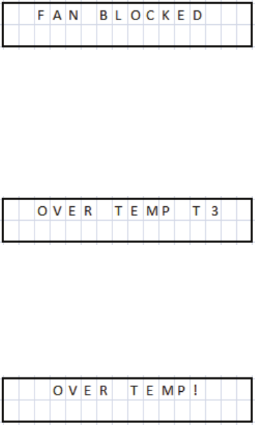
If the cooling fans stop working during operation this error
message will be displayed for about 3 seconds along with an
audible alarm (5 short tones). The Alarm indication LED
b
will illuminate and remain on. The BLA600 will continue to
function, as all of the other safety measures are still protecting
the amplifier, however we recommend that the cause of the
problem be investigated before further use. The cooling system
is an essential system for the correct function of the amplifier
and further damage may occur if ignored.
Indicates that the power supply has overheated. (>62°C). The
error message will alert the user and there will also be an audible
alarm of 5 short tones. The Alarm indication LED
bwill
illuminate. The amplifier will not be operational until the
temperature has fallen to an acceptable level, at which point the
amplifier will reset. If this occurs possible causes are the cooling
fans are not working, The inlet / exhaust for the cooling fans is
obscured or the amplifier is being used in an excessively hot
ambient temperature, or the amplifier has been in transmission
for an excessively long period of time
This indicates that the Heatsink temperature has reached 70°C.
The amplifier will sound 5 short audible tones and the Alarm
LED
bwill illuminate. The BLA600 will remain inoperable
until the temperature has reduced to 62°C at which point it will
automatically reset.
21
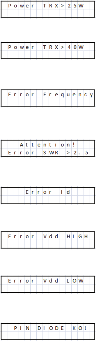
This indicates excessive input power from the Transceiver on
the bands from 80 to 10m. The amplifier will sound 5 short error
tones and the Alarm LED b will illuminate. Reduce the input
power and press the STB/OPR key d to reset the amplifier.
This indicates excessive input power from the Transceiver on
the bands 160 and 6m. The amplifier will sound 5 short error
tones and the Alarm LED b will illuminate. Reduce the input
power and press the STB/OPR d key to reset the amplifier.
This indicates that the transmission frequency is outside of the
predefined limits, (1.5-54MHz). The FCC version is also band
blocked, (26MHz –27.9 MHz). 5 short error tones will be
emitted and the Alarm LED b will be illuminate. Change the
transmission frequency, press the STB/OPR
dbutton to reset
the amplifier.
This indicates that the current antenna SWR is above 2.5:1 and
the amplifier will return to Standby. The amplifier will emit 5
short error tones the Alarm LED
bwill illuminate. To clear
the error check and adjust the antenna SWR then press the STB/
OPR
dbutton to reset the amplifier.
This indicates excessive Drain Current. The amplifier will emit 5
short error tones and the Alarm LED bwill illuminate. Check
that the amplifier is not being over driven and that the antenna
SWR is within acceptable limits <2.0:1. Then press the STB/
OPR
dbutton to reset the amplifier.
This indicates that the drain voltage is above 70V. 5 short error
tones will be emitted and the Alarm LED b will illuminate.
Check that the AC input voltage is correct. To reset the amplifier
press the STB/OPR
dbutton.
This indicates that the drain voltage is below 40V. 5 short error
tones will be emitted and the Alarm LED b will illuminate.
Check that the AC input voltage is correct. To reset the amplifier
press the STB/OPR
dbutton.
This error indicates a problem with the PIN Diode RTX
switching. 5 short error tones will be emitted along with the
Alarm LED b being illuminated. This creates a non recoverable
error and the amplifier will need to be switched off and on again.
If this problem continues you will need to contact technical
support.
22

12. Grounding:
It is beyond the scope of this manual to provide a definitive guide into the
controversial subject of RF grounding, as it is a subject all to itself and very much
depends on how the equipment is connected and types of antenna used. There are
both arguments for and against the stereotypical RF station ground. An additional
note is that lightning and static protection for the antennas is yet another subject, but
this should always be kept external to the building and will not be covered here.
There are many good articles about correct station grounding both online and in all
of the usual publications on ham radio from the ARRL and RSGB etc. As the output
power increases this becomes much more of a safety factor and should not be
ignored!
This section is here only to inform the user that it is an important consideration that
needs to be addressed and whether or not it needs to be implemented.
The classical RF ground consists of a series of ground rods driven into the ground
over a suitably large area. Connected together with heavy gauge wire or strap and
situated as close as possible to the radio installation, to which every piece of
equipment has a heavy gauge wire or strap connecting it to the RF ground. Most
commonly this is done with copper wire / *suitable copper braid or copper tubing to
the ground rods that are usually made from copper or copper coated steel. If using
copper particular attention should be made to the fact that copper corrodes and as it
does will lose its conductivity properties so a certain amount of maintenance will be
required as time passes. (*note: copper braid stripped from coaxial cable is not a
good idea. If the cable is left intact with both the centre conductor and outer
insulation present it can be used as a single conductor for ground connections but
removing the braid will make for a poorer RF conductor and will allow corrosion to
commence. There are ready made braids that are manufactured especially for this
use).
The distance of the RF ground to the radio installation and also the length of the
individual connections from equipment to the RF ground are very important and
depend on the frequency of use. They must be made as short as possible and much
less than a ¼ of a wavelength (). At 6m this can be difficult to achieve as at 52MHz
a ¼ is only 1.44m. If you have a ¼ of wire this will present a high impedance
and will impede the flow of RF to ground.
Antenna type, (balanced or unbalanced), fed with coaxial cable or balanced feeder,
proximity of the antenna to the shack, Antenna tuners and BALUNS etc all have an
effect on system performance and safety.
Typical examples are unbalanced antennas that cause RF to return back along the
outside of the coaxial cable screen and thus the equipment connected to it. This is
often described as ‘RF in the Shack’ and can cause many different issues, some
common ones such as tingling to the lips when touching a metal microphone grille,
or a tingling sensation when touching the CW key or metal chassis of the ATU /
23
Radio etc.
Another example is using an antenna tuner with a balanced feeder to the antenna.
It’s balanced right? Well, maybe not. If the tuner uses a ‘VOLTAGE’ BALUN,
(typically a 4:1 Ruthroff mounted in the ATU), and you have a high VSWR on the
balanced feeder, much greater than 50 ohms, the voltage BALUN can saturate, and
cause all manner of problems with balance, as can the balanced feeder if not
properly routed, coupling with close proximity to metallic objects. With high SWR
on the balanced feeder, (Which is all fine and good), you can have many thousands
of volts present. If you are using the wrong type of BALUN and you don’t have a
suitable RF Ground, consider the following. An impedance of 2500 Ohms at the
tuner and 500W output power, that will be the equivalent to well over 1000V of RF,
(V= (PxR)), touching that or even some fraction of it to your lips will certainly give
you something to remember! Simply using the correct type of BALUN, (A suitably
rated current BALUN would resolve this problem). But having a good RF ground
would at least provide a path for the RF to ground and keep you safe. The higher the
transmitted power the more dangerous this becomes.
Typical problems of RF in the shack are hot chassis, microphones and CW keys,
computers rebooting, monitors switching off, RF distortion on the transmitted audio,
or RF getting into power supplies, Multiple SWR meters at different points in the
same line giving different readings (Assuming of course SWR meters give same
results at the same point in the line), etc.
If a suitable RF ground cannot be made, for example, if the radio installation is not
on the ground floor, and maybe there are problems of RF being returned, then the
first solution would be to investigate why, look at antennas, how they are fed, what
type of BALUN is being used etc.
If this cannot be resolved a simple solution is to use a ¼ counterpoise at the
frequency that the problem occurs, or perhaps for all bands used, connected to a
common point on the back of the amplifier ground terminal or ATU ground terminal
and stretched out away from the equipment, bends and kinks are OK, (coiling them
up, not so much), that should help to alleviate the problem. Needless to say the wire
should be insulated and taped over at the far end, to protect from possible contact, as
this will be the point of highest voltage.
As a last point just because your station appears to have none of these effects at low
power, doesn’t mean that these problems are not present or that the problem is with
the power amplifier, when you receive a surprise from your hand touching the CW
key or lips on the mic. grille! Safety first!!
24

13. Warranty.
3 Costruzioni Elettroniche S.n.c. Guarantees that the product is free
from manufacturing defects both parts and workmanship for a period of 12
months. The warranty commences on the date of purchase. Any work
undertaken for the warranty must be carried out by 3 or an authorised 3
service centre.The costs of transportation, duties and insurance between
the purchaser and 3 or an 3 approved service centre are the
responsibility of the purchaser, both to and from the service centre. The
warranty must be requested to the distributor or reseller where the amplifier
was originally purchased. In the case where the original distributor or reseller
no longer exits or no longer deals with 3 products, 3 will communicate
the nearest distributor or reseller to use, or in the instance where this is not
possible/convenient, 3 will honour the warranty directly. If any repairs are
carried out outside of an approved 3 service centre this will void the
original warranty and 3 will not be responsible for any incurred charges.
The warranty will only be honoured if the amplifier has been used for it's
intended purpose as described in the operation manual and it is returned
with the original purchase receipt, that the amplifier is transported in the
original packing container, that the serial number is unchanged and readable
and that the warranty labels remain intact. The warranty does not cover the
RF power transistor or any aesthetic damage. Any change to the warranty
either by local law or that made by the distributor or reseller directly with the
purchaser will be the sole responsibility of the distributor or reseller and not
by 3. In the event of any argument between parties resulting in legal
action. It will be agreed to be settled in a court in Bologna (Italy).
The purchase of this product assumes that the purchaser has accepted the
terms and conditions of this warranty.
25

14. Specifications:
Frequency: 1.8-30 MHz & 50-54 MHz
LPF’s Optimised for 1.800-2.000 MHz
the following Bands: 3.500-4.000 MHz
7.000-7.300 MHz
10.100-10.150 MHz
14.000-14.350 MHz
18.068-18.168 MHz
21.000-21.450 MHz
24.890-24.990 MHz
28.000-29.700 MHz
50.000-54.000 MHz
Active Device: NXP / Freescale MRFE6VP5600H (50V)
Output Power: 500W+ PEP P1dB
Input Power: 20-25W for 500W O/P 80-10m
30-40W for 500W O/P 160m & 6m
Power Gain: Typical 14dB +/- 1dB (80-10m)
Output Harmonic / Spurious Distortion: HF >-45dB 6m >-60dBc
Input: 50 Ohms Unbalanced UHF SO239 Female
Input Matching: <1.5:1 VSWR (160-6m)
Output: 3x 50 Ohms Unbalanced UHF SO239 Female
Teflon Insulator, Gold plated terminal.
Supply Voltage: 120 Vac +5-5%
230 Vac +6-10%
240 Vac +10-6%
50/60Hz 1200VA max
AC Input Fuse: 5 x 20mm F LBC 250V (Fast Blow)
240Vac Supply 5A
230Vac Supply 6A
115Vac Supply 10A
PA Current: 27A max (hardware protected)
Metering: Drain Current (Id), Drain Voltage (Vd), Relative
Output Power, Input Power (Pin), Relative Load
VSWR, Heatsink Temperature, Transistor
Temperature, PSU Temperature.
26
PTT Input: Close to ground TX, Open Circuit RX, (Suitable
for Open Drain / Collector / Relay switching).
Output +5V S/C current <15mA in TX.
ALC Output: Negative going voltage, (0 to –10V), Adjustable.
Dimensions: 430mm x 142mm x 324mm (Width x Height x
Depth)
Weight: 21.5 kg
27