RONDISH TM-01 Cordless Pad Transmitter User Manual Rondish UI Strip Door Monitor DMS 01 03 v
RONDISH CO. LTD Cordless Pad Transmitter Rondish UI Strip Door Monitor DMS 01 03 v
RONDISH >
Users Manual
UI TL-2100GR V.01C
RONDISH
Cordless Bed Monitoring
System
USER INSTRUCTION
Important: Changes or modification to this product that is not authorized by the
manufacturer could void the FCC compliance and negate your
authority to operate the product.
Issued 28th Aug., 2008
CONTENTS
1. EQUIPMENT OVERVIEW
2. FEATURES FUNCTIONS AND SETTING UP INSTRUCTIONS
3. TECHNICAL SPECIFICATIONS
2

1.0 EQUIPMENT OVERVIEW
Providing the ultimate in convenience and ease of use, the Rondish cordless pad monitor requires no
cable to connect the Cordless pad with it’s pad monitor.
Communication between the Cordless pad that is placed under the sheets and the associated pad
monitor is by low power coded digital wireless.
The Cordless pad features connection with a low power wireless Transmitter Insert that is fitted and
enclosed inside a special pocket with stud fasteners.
A number of alert sounds and volume settings are selectable in the bedside monitor that has a ¼” jack
alarm output socket provided for connection via a cable to an existing nurse call system, if required.
Alternatively, this pad monitor can be operated with a standard wired pad having a cable with four pin
RJ11 plug via the four pin RJ11 socket and cable restraining point in the lower panel of the unit.
2.0 FEATURES, FUNCTIONS AND SETTING UP INSTRUCTIONS
There are three main components to a cordless bed monitoring system and these comprise:
Cordless Pad Monitor (TL-2100GR)
Cordless Pads (CBP-01 for 30” x 20” or CCP-01 for 15” x10”)
Fitted Transmitter Insert (TM-01)
2.1 The Cordless Pad Monitor (TL-2100GR)
Warning:
Changes or modifications to this unit not expressly approved by the party responsible for compliance
could void the user authority to operate the equipment.
NOTE: This equipment has been tested and found to comply with the limits for a
Class B digital device, pursuant to Part 15 of the FCC Rules. These limits are
designed to provide reasonable protection against harmful interference in a
residential installation. This equipment generates uses and can radiate radio
frequency energy and, if not installed and used in accordance with the
instructions, may cause harmful interference to radio communications. However,
there is no guarantee that interference will not occur in a particular installation.
If this equipment does cause harmful interference to radio or television reception, which can be
determined by turning the equipment off and on, the user is encouraged to try to correct the interference
by one or more of the following measures:
-- Reorient or relocate the receiving antenna.
-- Increase the separation between the equipment and receiver.
-- Connect the equipment into an outlet on a circuit different from that to which the receiver is
connected.
-- Consult the dealer or an experienced radio/TV technician for help.
2.1.1 P ad Monitor power supplies.
The Cordless pad monitor (TL-2100GR) may be powered solely from a fitted 9V battery. The battery is
fitted inside the battery cover found at the rear of the unit. In the event of “low battery” condition being
3
automatically detected, an alert will be triggered at the monitor with a single “beep” sound being emitted
at regular intervals, accompanied by flash of the monitor “Reset” button light (found on the front panel). In
this event, the battery should be replaced immediately.
If preferred and for secure operation, this Cordless pad monitor may be simultaneously powered from a
9Vdc regulated ac mains adaptor by connection via the 9V dc power socket provided. In this case, ac
mains failure, or removal will be automatically detected with a train of three quick “beep” sounds being
emitted at regular intervals, accompanied by flash of the monitor “Reset” button light. This alert will
continue until “Reset” at the monitor front panel, or ac power restored.
In the event of ac mains supply being lost, or disconnected the reset button on the front panel will “blink”
accompanied by the “beep” sound. In such event of ac mains supply failure, the fitted batteries will
continue to provide power to and support operation of the monitor for a time until the mains supply is
restored.
2.1.2 Cordless Pad Monitor automatic “low battery” indications.
The Cordless Pad Monitor will “beep” and the reset button will “blink” in the event of monitor “low battery”
being detected. In this condition, the Cordless Pad Monitor will continue to operate for a short time, but
the battery should be changed immediately.
2.1.3 Cordless Pad Monitor alert sounds.
A loudspeaker is fitted inside the front panel of the Cordless Pad Monitor for the various sound alerts and
indications.
Sound controls are located inside the battery cover found at the rear of the monitor.
These controls can be set for a selection of preferred sounds and sounder levels. If required, the monitor
can operate without any sounds (silent), while continuing to provide alarm light indications at the monitor
and calls to any interconnected nurse call system.
2.1.4 Monitor staff/operator controls.
One push button is provided on the front panel that illuminates in alert condition and is pressed by staff to
reset a bed leaving alarm, or other alert.
An alternative alarm reset point is provided on the lower front panel and marked “Caregiver Key”. A
switch is found recessed in the left hand side of the monitor can be set to “Reset On”, or “Caregiver Key
On”.
With “Reset On” selected, monitor alarms and alerts are reset by pressing the “Reset” button on the front
panel.
Setting this switch to “Caregiver Key On” provides a secure method for staff to reset an alarm and
prevents the risk of alarms being reset by other unauthorised persons. A magnetic key is provided for
this secure Safety Auto Reset™ operating method. In the event of a bed leaving alarm being triggered,
the “Caregiver Key” is applied by authorised staff at the point indicated at the lower front panel.
4
2.1.5 Cordless Pad Monitor signal monitoring and alert indications.
Two LED lights are located in the front panel of the Cordless pad monitor unit.
On the left hand side the “Check Pad” LED indicates if the signal is lost from the associated pressure pad
transmitter. Regular checking signals are automatically transmitted at 25 second intervals from the
associated cordless pad.
On the right hand side, the “Status/In Use” LED indicates when the monitor is actively receiving the
cordless pad periodic “Check Pad” signal (at 25 second intervals).
2.1.6 Monitor programming and setting up.
A button that is used in the setting up/programming sequence (below) is located inside the battery cover
in the rear of the monitor unit.
2.1.7 Monitor interconnection with nurse call system.
The monitor has a ¼” jack socket provided for interconnection with an existing bed head nurse call
system (if required). A standard cable is available as an accessory.
2.1.8 Monitor installation/mounting.
If preferred, the monitor may be wall mounted using the two screw slots provided in the rear of the
housing.
2.2 The cordless (wireless) pad with fitted transmitter module.
2.2.1 The bed pressure sensing pad.
The pressure sensing pad has a pocket with securing “snap” studs provided to accommodate the low
power wireless transmitter module. A short cable with miniature connector is found located inside this
pad transmitter pocket.
2.2.2 The low power wireless Transmitter Insert module.
The transmitter module has a short cable “tail” with a miniature plug that is connected to the pressure pad
connector cable (found inside the pad transmitter pocket).
2.3 Setting up instructions.
2.3.1 Preparation and programming.
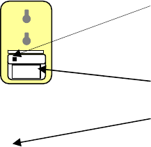
PROGRAM BUTTON
9V BATTERY
TRANSMITTER ACTIVE LED
5

TRANSMITTER INSERT MODULE
(a) Insert 9V battery into the cordless pad monitor unit.
(b) Press and release monitor program button found inside the battery compartment. Note that the
monitor will "beep" 3 times to indicate in "programming mode" and it's front panel "Status/In Use"
light is on. After a period of 30 seconds and with no further activity, the Monitor will automatically
exit “programming mode”.
(c) With the monitor in "programming" mode and within it's 30 seconds time-out period, slide the
on/off switch in the side of the nearby Transmitter Insert module to the "On" position. The
Transmitter Insert function light "blinks" to indicate "active" and the Monitor will emit one long
"beep" to indicate "programming successful. The monitor "In Use" light is extinguished and the
Monitor immediately exits "programming mode".
(d) Unfasten the “snap” studs and open the pocket of the cordless pressure pad and connect
Transmitter Insert to the short cable found inside the pocket.
Warning:
Changes or modifications to this unit not expressly approved by the party responsible for compliance
could void the user authority to operate the equipment.
This device complies with part 15 of the FCC rules. Operation is subject to the following conditions:
(1) this device may not cause harmful interference, and (2) this device must accept any interference
received, including interference that may cause undesired operation.
2.3.2 Testing cordless pad operation.
To test cordless bed monitor system in operation, press down on the pad. The Transmitter Insert function
light should "blink" and the Monitor should emit 2 "beeps" to indicate "system ready". Release the pad
and the Transmitter Insert will "blink", the monitor will continuously emit one of 3 selectable alarm sound
sequences and the monitor front panel "Reset" button will flash. Press the "Reset" button on the monitor
front panel to cancel alarm.
2.3.3 Application.
Place the Transmitter Insert module inside the pocket provided in the pad and “snap” the two
cover fastening studs together to secure the cover. The system can be checked at any time by pressing
and releasing the pad and observing that the Monitor responds correctly. The cordless pad system is
now ready to be put into service.
6
3.0 TECHNICAL SPECIFICATIONS
3.1 Cordless bed monitor
Electrical
3.1.1 Power: 9Vdc. PP3 battery and/or 9Vdc regulated ac mains adaptor.
3.1.2 Visual Alarm: Blue LED inside front panel reset button.
3.1.3 Audible Alarm: Selectable sounds with level adjust inside battery cover.
3.1.4 Alarm Interconnect: Volt free relay contact output via ¼” jack socket.
3.1.5 Pressure Pad Connection: Digital wireless (cordless), or cable via RJ11 four pin socket.
3.1.6 Other Automatic Alerts: “Check Pad”, “Status/In Use”, “Low Battery” and “AC Lost”.
3.1.8 Cordless Technology: AM coded digital wireless super heterodyne receiver.
3.1.9 Cordless Operating Frequency: 433.92MHz (Low Power License Exempt).
Mechanical
3.1.10 Housing: White ABS plastic
3.1.11 Dimensions: 110x77x 28mm.
3.2 Cordless Pad Transmitter Insert
Electrical
3.2.1 Power: Two 3V Lithium batteries.
3.2.2 Visual Indicator: Red LED transmit on indicator (“Status/In” Use).
3.2.3 Pressure Pad Connection: Miniature two pin connector inside pad pocket.
3.2.4 Cordless Technology: Encodable AM digital wireless transmitter.
3.2.5 Cordless Operating Frequency: 433.92MHz (Low Power License Exempt).
Mechanical
3.2.6 Housing: White ABS/polycarbonate plastic.
3.2.7 Dimensions: 68x54x10mm
7