Contents
- 1. User manual part 1
- 2. User manual part 2
User manual part 2

,!$ "!
To enter the Setup menu hold the Caregiver Key (C-Key) for several seconds.
When navigating the Care Station menu, use the A-Key to cycle through the options,
and C-Key to confirm the choice.
1. Add/Del PAD & MAT
2. Add/Del Sensor
3. OORC Status
4. Set Sys. Time
,0##7(&(8
This will allow staff members to manage Cordless chair pads and floor mats. Select
the type of devices from BedPAD, ChairPAD, or FloorMAT, and then activate the
transmitter to enter the device into the Care Station memory.
You will then be prompted to enter a six digit ID for the device, which will be displayed
during any alarm.
,##7(&"
The Protector System also supports other types of RF sensors, such as PIR, Gas,
Smoke or magnetic Door Contact sensors. These types of devices have total
12-digit address and data bits. The Protector System uses only 6 digits; the others
should be fixed, or will not be recognized.
A0 A1 A2 A3 A4 A5 A6 A7 D3 D2 D1 D0
O O X X X X X X X X O O
‘O’ – the bit should be ‘Open’, do not short to anything,
‘X’ – the bit can be short to ‘H’, ‘L’ or ‘Open’.
For PIR sensor, D3 and D2 are set to ‘O’, and for Door Contact sensor, D3 set to ‘L’
and D2 set to ‘O’.
Bits A2-A7 must have a unique configuration within the network.

,,!
This stands for Our of Range Status, and will search for any devices programmed into
the system whose signals are not being received by the network. You should either
check the status of devices in the Lost List, or remove them from the memory of the
system if they are not being used.
,3
You can set the time and date here.
,,(7+. #
The Care Station has an option to silence alarms, which is activated by selecting
Night Mode.
In normal operating mode the LCD display will show……
To select night mode, press and hold the A-Key to enter the Operation Mode menu.
Use the A-Key again to select Day or Night. The menu will exit automatically after
several seconds.
Wireless D/N
Care Station
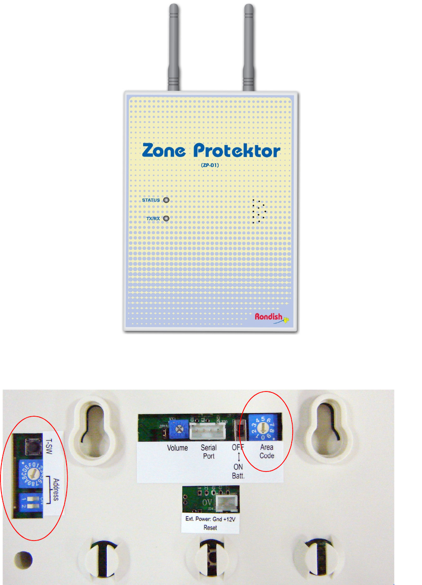
3) )/*9
FRONT PANEL VIEW
(ZP-01)
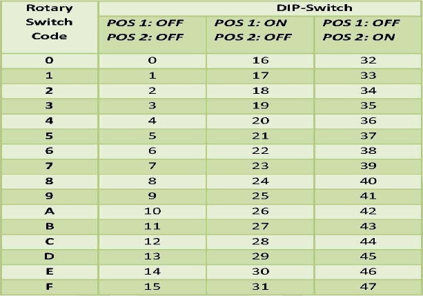
REAR PANEL VIEW
#
There are 5 steps to program each Zone Protektor.
1. Set Network ID
2. Set High Frequency Wireless Channel (must match Master Care Station)
3. Set Target Address
4. Set Zone Protektor Address
5. Set Site/Area Code
Enter programming mode to set the Network ID, Channel, and Target Address.
Press and hold the T-SW button until the Tx/Rx LED on the front panel flashes and
remains on.
30 2(
The Network ID setting must be the same for all Zone Protectors and Master Care
Station communicating on the same High Frequency network and prevents receiving
unwanted calls from a nearby system.
Adjust the “Address” rotary switch to the required Network ID:
0-3 (factory default =“0”)
Then press the T-SW button once and the Tx/Rx LED will flash once to accept the
input.
30/+.'!"-9&.""&
The High Frequency wireless channel must be the same as that chosen on the
Master Care Station. This can be adjusted using the rotary switch at “Address” to
set a new digit:
0-4 for the 868MHz frequency band (CE)
0-9 for the 916MHz frequency band (US).
Press the T-SW button again to confirm the setting.
>
3,0+##
The Target Address for the ZP-01 to communicate with the Master Care Station,
should be set to “48” (i.e. = <MO> as set at Master Care Station), or the address of
another Zone Protektor.
(1) Adjust the rotary switch to “4” and press the T-SW button,
(2) Adjust the rotary to “8” and press T-SW again.
(3) The Tx/Rx LED will then come back on and stay on “steady” briefly to indicate
“programming finished”.
(4) The ZP-01 then automatically exits programming mode, reboots itself and returns
to normal operating mode.
330* " 2 ##
This parameter tells the Master Care station where to send signals. This ZP
address” (“00-47”) must be unique within the system so it can be individually called by
the Master Care Station and various Call Points.
The ZP-01 unique address is set by adjusting the rotary and DIP switches at
“Address”. This setting can be selected without entering “Program Mode”.
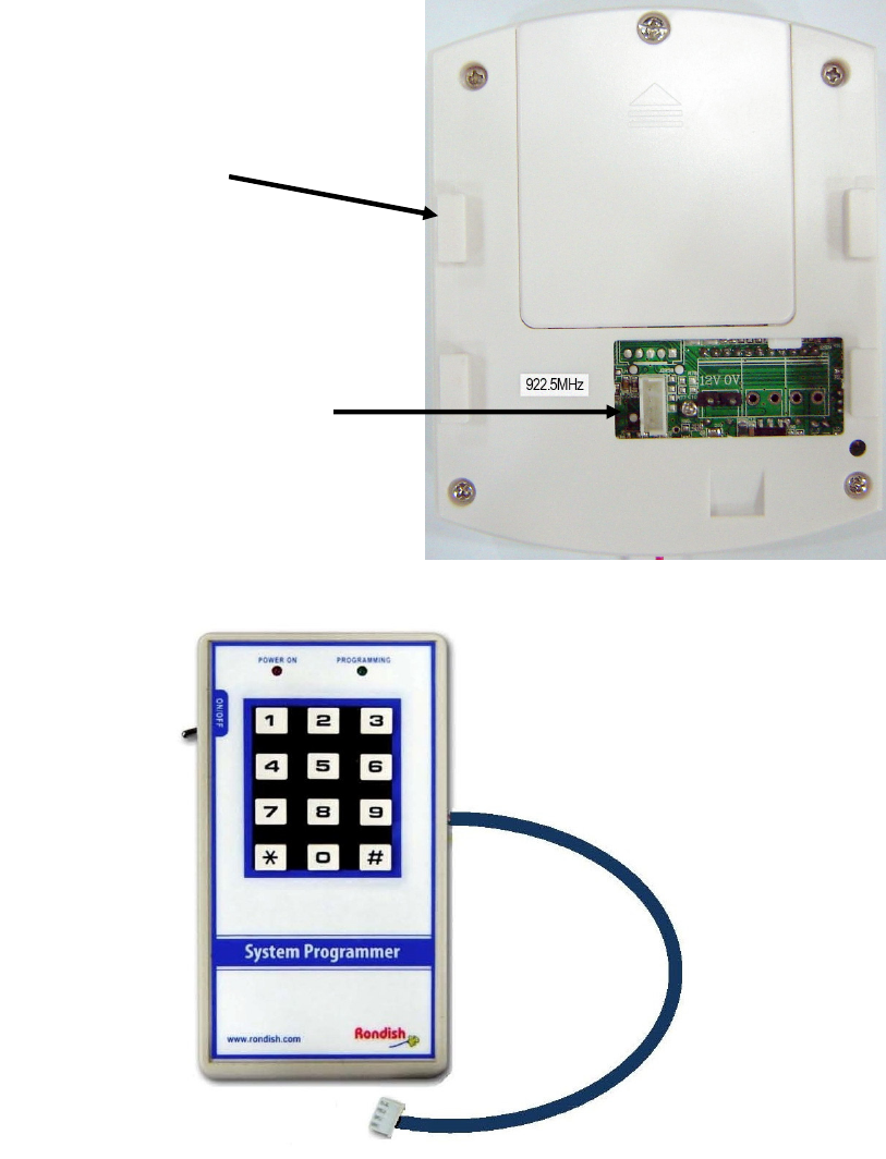
The matrix chart below can be referred to when adjusting the rotary and DIP switches
to set the required ZP Address.

For example, setting ZP Address to “18”:
(1) setting of “2” on the rotary switch
(2) setting of POS 1: ON and POS 2: OFF on DIP switch
When this is changed the ZP-01 should be turned off and then back on.
340"+7 #
This feature will prevent a Zone Protektor from processing calls from equipment in
different areas, and a Slave Monitor (see page 13) can then be used to display calls
from only within the area.
This can be set at the Zone Protektor without the need to re-enter “programming
mode” by setting the separate rotary switch found above at “Area Code” (0-9).
The Master Care Station should be set to Area “0” so it receives calls signals from
any Protektor II equipment within wireless range, regardless of site area. If no Slave
Monitors are planned for the network, set every Zone Protektor area to “0”.
When this is changed the ZP-01 should be turned off and then back on.
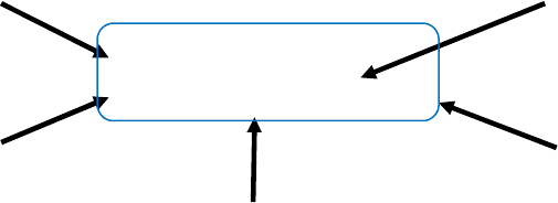
4) )
In order to program Call Points (WLSCP-02), you will need to use a System
Programmer, which connects to the port shown below. It will help to read through
section 5.2 and first create all the programming strings based on how you want
alarms displayed at Protektor Care Stations.
Power On/Off Switch
Programming Cable
WLSCP-02 CALL POINT
REAR VIEW
For Wall Mount
Cradle
Plug Programming Cable into
Call Point Programming Port
BATTERY HOUSING
SYSTEM PROGRAMMER
4 + $"+"!- "
To use the Rondish System Programmer, just plug the Programming Cable into the
Call Point Programming Port (shown above) and turn on the power switch. Each
Call Point (WLSCP-02) must be programmed for Network Configuration and
Installation Position; the Device Configuration will not always need programming.
1. Network Configuration
2. Device Configuration
3. Installation Position
4 + "+"+1 && "
Enter the programming “strings” described in each section below. If an error has
occurred during input, press “#nnn” and re-start from the beginning of the input
“string”. A programming example will follow, which shows a hospital ward.
40 2 "1+! "
The “program string” is #000 ZZ AA S. Where:
• # = “Ready to Program”
• 000 = Network Configuration Program Code
• ZZ = “Zone Protektor Address” of nearest ZP-01 unit (00-47)
• AA = Call Point Zone Address within this area/zone (00-63)
• S = Site/Area Code (0-9)
Typical Care Station Display
Callpoint Alarm
Ward : 0310 Bed : 01
3:143@A3B
5CD76/E93/6;<
--0 @A3B
5CD76/E93/6;<
/99-12655,377B
5CD76/E93/6;<
/99-126@A3B
5CD76/E93/6; <
/99-126B
5CD76/E93/6;<

Notes:
1. The Call Point Zone Address code can be chosen and set for 00-63 within the
operating area of an individual Zone Protektor. This address tells the Care
Station how to contact the Call Point, and must not be repeated for each ZP.
2. The Site/Area code allows a Slave Monitor to display alarms from only its
area. The Slave Station, Zone Protektor and Call Point areas must match.
40(- "1+! "
With the programmer still powered up, you may then continue by keying # again and
inputting the string. This string will not always need to be entered.
The program string is #010 P LL G. Where:
• # = “Ready to Program”
• 010 = Device Configuration Program Code
• P = Product Type (3 = “Bath Alarm Button” or 8 = “Call Point”)
• LL = Presence Area (0-31)
• G = Group Reset Facility (0 = Turn Off, 1 = Turn On).
Presence Area (LL)
Caregiver may press the “Presence” button to light the green colour at the indication
Call Light and notify the Master Caregiver Station of location, ID and ”Presence 1”.
While this Call Point is in “Presence” mode, if another Call within the zone with the
same “Presence” code (Presence Area) is activated, the Call Point will alert the
caregiver another call has been activated from within it’s “Presence Area” with a
flashing LED and beeping at intervals of 15s.
Group Reset (G)
Within a particular Zone Protektor “Zone”, if “G” is turned on (i.e. set to “1”), operating
any single Call Point “Reset” button with this Protektor zone location will reset any, or
all activated Call Point/s that have been programmed for “Group Reset On” in that
Protektor zone.
If G at any Call Point within this zone is set to “0” it will not be reset, even if another
Call Point Reset button set to “1” within this “RRRR” group is pressed.
4,0"&& " "
With the programmer still powered up, you may then continue by keying # again and
inputting the string. The program string is # 020 T RRRR U BB. Where:
• # = “Ready to Program”
• 020 = Installation Position Program Code
• T = Room Type
• RRRR = Call Point Address
• U = Call Point Type
• BB = Call Point ID
Room Type (T)
For “T”, choose the appropriate digit from the following options. This will adjust how
the call is displayed at Protektor Care Stations. If this number is set to ‘0’, it’s display
will be based on the Global Settings at the Master Care Station (section 3.3).
1 = Room
2 = Flat
3 = Ward
4 = Home
5 = Apartment
6 = Area
Call Point Address (RRRR)
This differs from the Call Point Zone Address (AA), and determines how the Care
Station will display the alarm location. There are four digits, which can be used in
any combination to represent floors/buildings and rooms. A common practice is to
use the first two digits for floor, and the second two for room number.

Call Point Type (U) + Call Point ID (BB)
This allows the Call Point / Bath Alarm Button to display its location within a building,
ward, or area chosen at “Room Type”.
If Product Type P = 8 (Call Point), can choose:
U BB
0 = Bed + 01-60. (This zone can have up to 60 beds).
1 = Living Room + 01-03. (Can have up to 3 rooms)
2 = Corridor + 01-03
3 = Kitchen + 01-03
4 = Stairs + 01-03
5 = Lift + 01-03
6 = Roof + 01-03
7 = Garage + 01-03
8 = Garden + 01-03
9 = Section TBA + 01-09
If Product Type P = 3 (Bath Alarm Button), can choose:
U BB
0 = Toilet + 01-20.
1 = Disabled + 01-09
2 = Shower + 01-09
3 = Bath + 01-09
4 = Male + 01-20
5 = Female + 01-20
6 = Section TBA + 01-20
Program string #000 ZZ AA S
#000 Network Configration
ZZ Target ZP-01 unit (00-47)
AA Call Point Zone address (00-63)
S Site code (0-9)
Program string #010 P LL G
#010 Device Configuration
P Product type (3 (Bath) or 8 (Call point) only)
LL Presence Area (0-31)
G Group reset (0 (off) or 1 (on) only)
Program string #020 T RRRR UBB
#020 Installation Position Configuration
T Room Type
1 Room
2 Flat
3 Ward
4 Home
5 Apartment
6 Area
RRRR Call Point Address (4 Digit)
UBB When "#010" P code = 8
Call Point Type Call Point ID
0 Bed 01-60
1 Living Room 01-03
2 Corridor 01-03
3 Kitchen 01-03
4 Stairs 01-03
5 Lift 01-03
6 Roof 01-03
7 Garage 01-03
8 Garden 01-03
9 Section TBA 01-09
When "#010" P code = 3
Bath Alarm Type Bath Alarm ID
0 Toilet 01-20
1 Disabled 01-09
2 Shower 01-09
3 Bath 01-09
4 Male 01-20
5 Female 01-20
6 Section TBA 01-20
430 + "+! 1 && "
4, + "+9$ 1&& "
Waterproof call points do not have a connection point for the system programmer.
These use similar programming strings as described above, but they must be entered
manually using a caregiver key and the call button.
To enter programming mode, apply the C-Key to the green triangle until the LED
begins flashing and then hold the call button for ~5 seconds until the LED stays on.
Instead of beginning programming string with #000, #010, or #020 as with the system
programmer, you will instead enter a two-digit password. To enter a digit, press the
call button the desired number of times and confirm by touching the C-Key. To enter
‘0’ do not press the call button before touching the C-key again. The LED will flash
acknowledgment each time.
The programming strings should follow the below format:
21 ZZAAS
22 PLLG
23 TFFRRUBB
Note:
1. Entering the device configuration string will often not be necessary. Factory
default is (P = 3, bathroom type), (LL = no presence area), (G = no group
reset).
2. WCP-04 units will be sent from production in “Sleep Mode”. To exit this
mode, press and hold the Call button for ~10 seconds. The call point can be
put back into sleep mode by entering password “25”
#
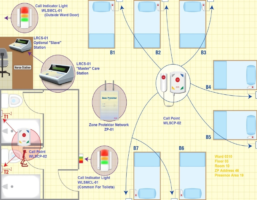
43: $&0 + "+&& "1 / $&9#
Programming example and Guide for
7x Bed Hospital Ward
2x Bath/Toilet Areas,
Floor 03,
Ward 10,
Presence Area Code 19,
Nearest Zone Protektor = 46
The following equipment might be installed in this Ward:
7x WLSCP-02 Call Point (Bed Head) with NEC-02 Extension Cord
1x WLSCP-02 Pull Cord in Toilet T1
1x WLSCP-02 Pull Cord in Toilet T2
2x WLSMCL-01 Call Indicator Light (Ward Entrance and common Toilet area)
1x LRCS-01 Care Station (Nurse Station)
1 x ZP-01 Zone Protektor
>
Program Ward 10 Bed Head Call Points (1 – 7)
Bed 1:
Network Configuration: #000-46-01-0
Device Configuration: #010-8-19-0
Installation Position: #020-3-0310-0-01
Bed 2:
Network Configuration: #000-46-02-0
Device Configuration: #010-8-19-0
Installation Position: #020-3-0310-0-02
Continue to program Beds (up to Bed 7)…
Program Toilet 1 Call Point
The programming will be almost the same, except the device configuration must be
set to bath, and programming will begin with a password if the WCP-04 units are
used.
Network Configuration: 21-46-08-0
Device Configuration: 22-3-19-0 (P=3)
Installation Position: 23-3-0310-0-01 (U=0, BB=01)
(T) Room Type “Ward” = “3”
(U) Call Point Type “Bed” = “0”
(LL) “Presence” Area Code = “19”
Care Station
Display For
Bed ID 01 above
Care Station Display for Toilet
ID 01 above
Callpoint Alarm
Ward : 0310 Bed : 01
Callpoint Alarm
Ward : 0310 Bed : 02
Bath Alarm
Ward : 0310 Toilet : 01
(ZZ) ZPID = “46”
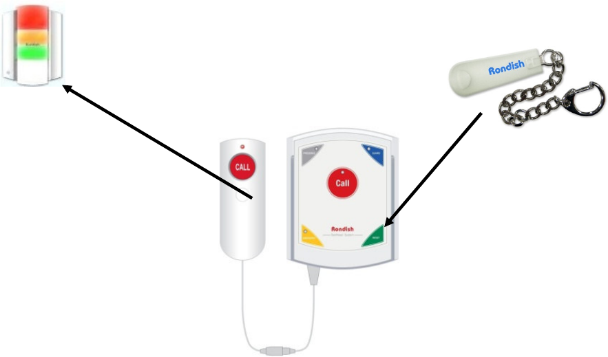
5) ) ()/
The Multi-color Indication Light can be located over a Flat, Ward entrance, or any
other doorway. It will act as a transponder/extender to zone Protektor units for area
Call Point alarms and can also be used as a call indicator outside a toilet area.
No address codes are programmed into the light unit as it is essentially a “Read In”
and data forwarding device. It has LED arrays producing lights in 4 colours, i.e.
1. (a) “Steady” Red for Nurse call from WLSCP-02 Call Point.
(b) “Flashing” Red for Emergency (Code Blue).
2. “Steady” Green for Presence 1
3. “Steady” Orange for Presence 2
4. (a) “Steady” White for Nurse call from toilet, or bathroom
(b) “Flashing” White for Emergency
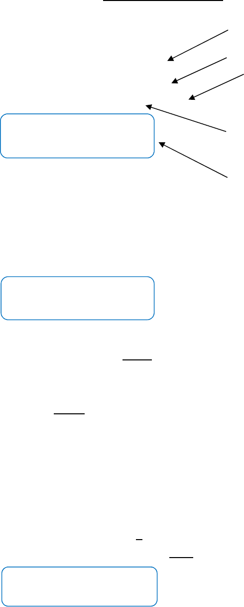
There are 4 steps to setting up and programming the WLSMCL-01 Light Unit.
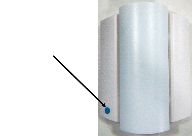
C-Key Application Point
5#!& ".+.
Place the C-Key at the point indicated on the front of the WLSMCL-01 housing and
hold for around 6-8 seconds.
(a) It will first enter into record mode and a single “beep” will be heard.
(b) It will then emit 3 continuous short beeps followed by 2 short beeps.
(c) Then the WLSMCL-01 lights flash in 2 groups i.e. Red + Green and Orange +
White.
(d) The WLSMCL-01 then emits 3 long beep sounds to confirm “Memory Erased”.
5$ ;#<"=&& "
Placing The C-Key briefly at the point indicated on the front panel, the WLSMCL-01
first emits a short beep and then 3 short beeps to confirm “read-in mode”. If the light
unit receives no more activity for a period of 1 minute, it will automatically exit learning
mode and return to normal operation.
To read-in a programmed Call Point to the light unit, briefly apply the C-Key to the
Call Point over the Reset button for about 6 seconds to transmit the code to the Light
Special “Read-In” Code
Transmitted to Light Unit
MULTI-COLOUR
INDICATION LIGHT
(“READ-IN” MODE)
Apply C-Key Here
PROGRAMMED
CALL POINT
CAREGIVER KEY (C-KEY)
unit while it is still in “read-in”. This Call Point ID and data will be recorded in the light
unit memory.
Further associated Call Points in the area assigned to this light unit may then be read
into its memory while it is still in “read-in” mode by applying the C-Key to the reset
point on call point front panels.
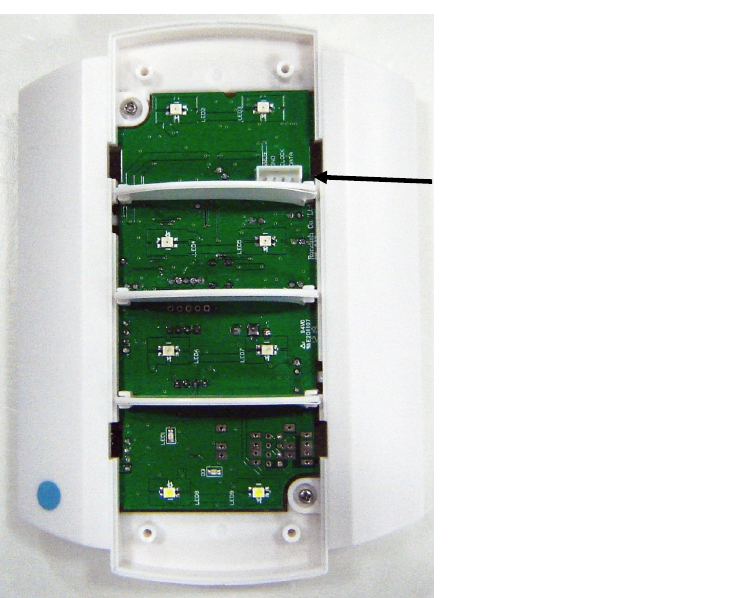
5,!""+>!??7"##@!"+("&
Use the Rondish System Programmer, plug the Programming Cable into the Light
Programming Port (shown above) and turn on the power switch.
The program “string” is #000 B. Where: B = Buzzer on (1), Buzzer off (0)
The program “string” is #001 U TT. Where: U = Unit (0 = second, 1 = minute) and
TT = time from 0-60
WLSMCL-01 INDICATOR
LIGHT (FRONT VIEW WITH
LENS REMOVED)
Programming Port for
Program Cable
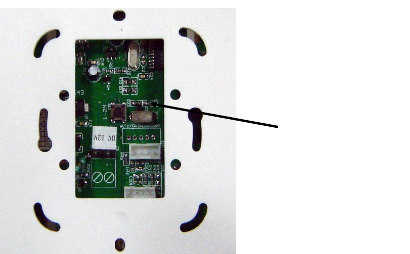
53"+ <9 # -.
This two-way “mode” switch may be set for:
(a) Mode 1: Light Indicator only (it will not forward any calls to the ZP-01 network).
This is important when operated as a light indicator only e.g. outside a toilet area
and to avoid wireless contention with transmission (to a Zone Protektor) from
other local light units.
(b) Mode 0: In addition to the Light Indication, it will forward the call/data to the Zone
Protektor network.
Note: When the light unit is operated for e.g. at a toilet, the call point is programmed
as “3” (“Bath”), then automatically only the white colour light will operate.
WLSMCL-01 INDICATOR LIGHT
(REAR VIEW)
Two-Way “Mode”
Switch