RSI VIDEOTECHNOLOGIES DV50 Outdoor Motion Viewer User Manual Installation sheet
RSI VIDEOTECHNOLOGIES Outdoor Motion Viewer Installation sheet
Installation sheet

Product Summary
The Outdoor MotionViewer Model DCV651 is a wireless,
battery operated, outdoor motion activated camera de-
signed for use in RSI Video Technologies security systems.
Motion-activated cameras are intended for applications
where video verification of intrusion alarms is necessary or
desired.
> Lithium batteries for long life
> Wide angle lens
> Infrared LED for night illumination
> Standard motion coverage lens (30 ft./9 m distance)
> IP65 weather proof housing
> Low Temperature operation (-20°f to + 140°f)
> Transmits check-in/status signal every 8 minutes
Installation Guidelines
For easier installation, programming and RF testing
should be done to check for good communication between
the control panel and all system devices before mounting
system devices.
Install the detector and other system devices in the order
of the following steps:
> Programming/RF Testing - program detector and
all other devices into the control panel and test RF
communication from each intended device location
to the control panel.
> Mounting - mount detector at the tested location.
Programming/RF Testing
The following provides summarized steps for device
programming and testing. For complete details, refer
to the control panel installation manual.
1 Remove all 4 screws, separate base
from camera and install batteries.
2 Put control panel into
programming/configuration mode.
3 Using a programmed alphanumeric
keypad, proceed through menus
until the display shows ADD A
NEW DEVICE.
4 Press Yes. The display shows PRESS
PROGRAM BUTTON OF DEVICE.
5 Press and release program button
on the MotionViewer.
The camera LED flashes. Wait for
keypad display to show CAMERA
(1 - 25) PROGRAMMED.
6 Press Yes. The display shows
RADIO RANGE TEST? Press Yes
again. The camera LED starts
flashing and keypad display
shows RF TEST ( #/5 or #/9).
7 Take camera to its intended mounting location and
make sure LED flashes continuously or you receive a 5/5
or 9/9 indicating good communication with the control
panel.
9 Press YES to end radio range test, then press Esc/No.
10 The display shows AREA ALLOCATION AREA: 1. Press
either arrow button repeatedly until desired AREA
number appears, then press Yes.
11 The display shows NAME + LOCATION. Enter appropriate
device name/location (up to 16 characters), then press
Yes. The display shows the device number and name
for your verification.
12 The display shows FUNCTIONAL DEVICE
TEST? Press Yes again and verify camera operation.
For example, wave your hand in front of the sensor to
activate its LED indicating detection. (walk test LED)
13 Press Yes to end detection verification.
14 The display shows OPERATION COMPLETED or ADD A
NEW DEVICE? Press Yes
Repeat steps 1 – 14 for remaining cameras.
15 When finished, exit from configuration mode.
www.videofied.com
PRODUCT INSTALLATION SHEET
Outdoor MotionViewer DCV651
Made by RSI VIDEO TECHNOLOGIES 2204 - OMVIS March 2012
Mounting
> Use proper tools and hardware.
> Mount using 1/4” x 20 thread mounting bracket only.
> Mount camera 7.5 to 9 feet (2.3 to 2.8m) from the floor.
> Mount detector aimed at area to protect.
> Do not aim detector at windows, especially those that
let in direct sunlight, or at heat sources such as lamps,
fireplaces, radiators, and heating vents.
> Do not aim detector at moving objects such as curtains,
fans or animals.
1 Separate base from camera.
2 Hold mount base against
mounting surface and mark the
appropriate mounting holes.
3 Place camera mount on
mounting surface
so holes line up with
pilot holes/anchors and secure
base with appropriate screws.
4 Thread the MotionViewer onto the mount
WARNING : Do not cover the Fresnel lens !
Outdoor MotionViewer DCV651 INSTALLATION DATA SHEET
www.videofied.com
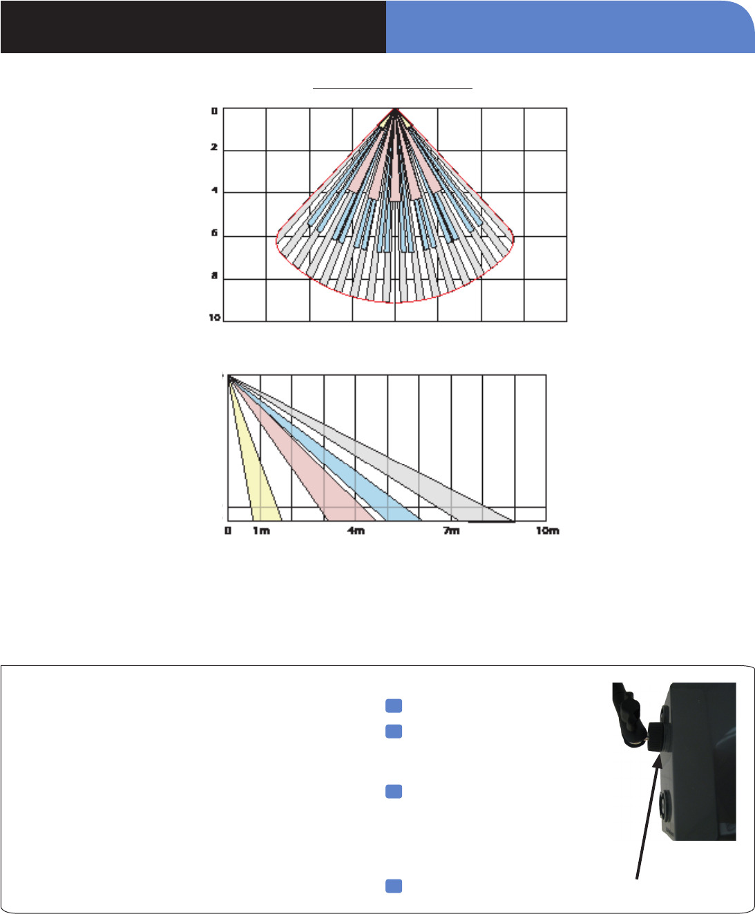
PIR Detection Pattern
Outdoor MotionViewer DCV651 INSTALLATION DATA SHEET
www.videofied.com
Self protection
of the camera
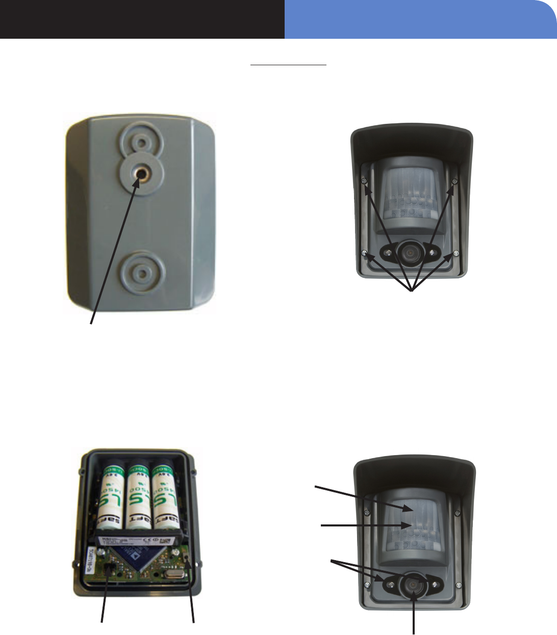
Program Button
Device Layout
Cover Screws
Indicator LED
Motion Detector
Infrared Illumintors
Camera
1/4” x 20 thread for mounting
bracket

INSTALLATION DATA SHEETOutdoor MotionViewer DCV651
Electrical Data
Panel Compatibility XL, Visio, XT, XTIP
Power requirements Three 3.6 V Lithium AA batteries
Nominal Voltage 3.6V
Low Battery Limit 2.7V
Battery type SAFT Lithium AA LS14500
Battery life (estimated) Up to 4 years
RF technology S2View®
Radio type Spread Spectrum Bidirectional
Operating frequency 915 MHz. (US)
Transmission security AES encryption algorithm
Supervision Panel polls devices every 8 minutes
Antenna Integrated
Tamper detection Cover tampered
Camera sensor type CMOS black and white
Camera resolution 320 x 240 pixels
Camera sensitivity 0.2 lux
Camera lens Wide angle 85 degrees
Camera response less than 100 milliseconds
Video sequence in intrusion 5 frames/s for 10 seconds
Night illumination 2 infrared LEDs
Night illumination switching Automatic
Night illumination distance Up to 40 ft./ 12 m
Motion detector technology Passive infrared DSP
Motion detector type Dual element
Motion lens Fresnel
Motion Detection angle 85°
Motion Detection distance
Up to 40 ft./12 m depending on
local environment and temperature.
Motion Detection pattern 24 facets
9 main-40 ft./12 m
8 intermediate-26 ft./8 m
5 short-13 ft./4 m
2 creep zones-4 ft./1.2 m
Operating temperature -20° - +140° F (-30° - +60° C)
Maximum relative humidity 95%, non-condensing
UL listings FCC Part 15C
Physical Data
Material Polycarbonate UL94
Dimensions (LxWxD): 4 in. x 3 1/2in. x 4 1/2 in.
(101.6 mm x 88.9 mm x 114.3 mm)
Weight 9.2oz./260.8 g (without batteries)
Installation/Mounting
Unit/Base Has a single thread for Gimble Mount
(Sold Seperate)
Mounting height 7.5 to 9.0 ft. (2.3 to 2.8 m)
www.videofied.com

EMEA SALES
23, avenue du Général Leclerc
92340 BOURG-LA-REINE
FRANCE
Hotline: +33 (0)820 846 620
Fax: +33 (0)1 82 69 80 10
© 2011 RSI VIDEO TECHNOLOGIES. VIDEOFIED® is a Registered Trademark of RSI VIDEO TECHNOLOGIES.
S2View® is a registered trademark of RSI VIDEO TECHNOLOGIES. Specications subject to change without notice.
USA SALES
4455 White Bear Parkway, Suite 700
White Bear Lake, MN 55110
USA
Hotline: +1 877 206 5800
Fax: +1 651 762 4693
www.videofied.com
FCC Regulatory Information for USA and CANADA
FCC Part 15.21 Changes or modifications made to this equipment not expressly approved by RSI VideoTechnologies may void the FCC
authorization to operate this equipment.
FCC Part 15.105 Class B
This equipment has been tested and found to comply with the limits for a Class B digital device, pursuant to Part 15 of the FCC Rules.
These limits are designed to provide reasonable protection against harmful interference in a residential installation. This equipment
generates, uses and can radiate radio frequency energy and, if not installed and used in accordance with the instructions, may
cause harmful interference to radio communications. However, there is no guarantee that interference will not occur in a particular
installation. If this equipment does cause harmful interference to radio or television reception, which can be determined by turning the
equipment off and on, the user is encouraged to try to correct the interference by one or more of the following measures:
• Reorient or relocate the receiving antenna.
• Increase the separation between the equipment and receiver.
• Connect the equipment into an outlet on a circuit different from that to which the receiver is connected.
• Consult the dealer or an experienced radio/TV technician for help.
Radio frequency radiation exposure information according 2.1091 / 2.1093 / OET bulletin 65
This equipment complies with FCC radiation exposure limits set forth for an uncontrolled environment. This equipment should be
installed and operated with minimum distance of 20 cm between the radiator and your body.
This transmitter must not be co-located or operating in conjunction with any other antenna or transmitter.
This device complies with Part 15 of the FCC Rules and with RSS-210 of Industry Canada.
Operation is subject to the following two conditions:
(1) This device may not cause harmful interference, and
(2) This device must accept any interference received, including interference that may cause undesired operation.
Outdoor MotionViewer DCV651 PRODUCT INSTALLATION SHEET