RSI VIDEOTECHNOLOGIES MV00 Indoor Motion Viewer User Manual Installation Manual
RSI VIDEOTECHNOLOGIES Indoor Motion Viewer Installation Manual
Installation Manual
Made by
RSI VIDEO TECHNOLOGIES
IMV Indoor Motion Viewer - Install sheet Ed05EN
1/5
Indoor Motion Viewer IMV
PRODUCT INSTALLATION SHEET
Product Summary
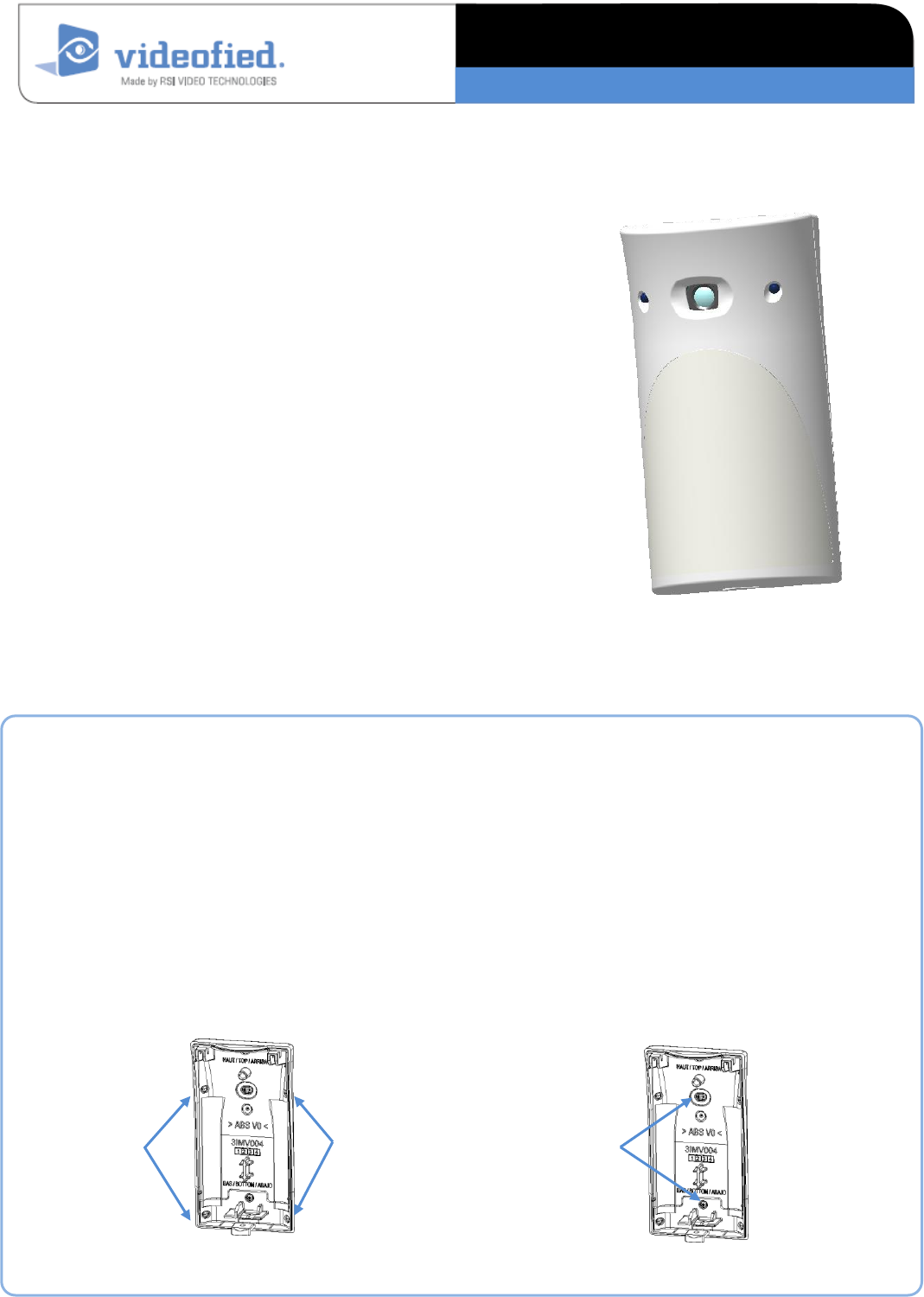
The MotionViewer IMV is a wireless, indoor motion activated camera
designed for use in a Videofied™ security system. The camera
includes the following features:
Lithium batteries for long life
Color day / B&W night
Wide angle lens
Infrared LEDs for night illumination
Standard motion coverage lens (30 ft./9 m distance)
Dual tamper function provides detection of both wall and cover
tamper.
Transmits check-in/status signal every 8 minutes
Installation Guidelines
For easier installation, programming and RF testing should be done to
check for good communication between the control panel and all
system devices before mounting.
Install the detector and other system devices in the following order:
Programming / RF Testing: program detector and all other devices
into the control panel and test RF communication at each
intended device location to the control panel.
Mounting: mount detector at the tested location.
Mounting rules
Use proper tools and hardware.
Mount indoors in a temperature controlled environment.
Mount camera 2.1 to 2.3 m (6.9 to 7.5 ft.) from the floor.
Respect Top and Bottom side of the Motion Viewer
When possible, mount in a wall corner in order to aim at a complete room
Mount detector on an outside wall, aimed at area to protect.
Do not aim detector at windows, especially those that let in direct sunlight, or at heat sources such as lamps, fireplaces,
radiators, and heating vents.
Do not aim detector at moving objects such as curtains, fans or animals.
Do not cover the Fresnel lens
Corner Mounting
Use only 2x screws on the same side (left or right) to mount the casing on the
corner
Flat Wall Mounting
Flat wall
mounting
holes
Corner
mounting
holes
Corner
mounting
holes
IMV Indoor Motion Viewer - Install sheet Ed05EN
2/5
Indoor Motion Viewer IMV
INSTALLATION DATA SHEET
Programming / RF testing / Mounting
The following provides summarized steps for device
programming, testing and mounting. For complete details,
refer to the control panel installation manual.
1
1
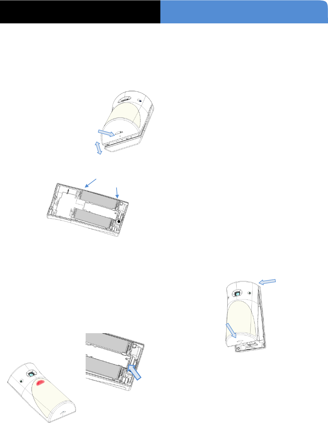
Loosen bottom screw ① (if present),
separate base from IMV ②.
2
2
Install 2 SAFT LS14500 3.6V lithium batteries, observing
correct polarity.
Check that LED flashes before staying red.
3
3
Put control panel into programming/configuration mode.
4
4
Using a programmed alphanumeric keypad, proceed
through menus until the display shows ADD A NEW
DEVICE.
5
5
Press Yes. The display shows PRESS PROGRAM BUTTON
OF DEVICE.
6
6
Press and release program button on IMV using
your finger or a screw driver ①.
The IMV LED flashes red ②.
Wait for keypad display to show CAMERA (1 - 24)
PROGRAMMED.
7
7
Press Yes. The display shows RADIO RANGE TEST?
Press Yes again. The IMV LED starts flashing and keypad
display shows TEST IN PROGRESS.
8
8
Move the IMV to the intended mounting location and
make sure you receive a 5/5 or 9/9 indicating good
communication with the control panel.
9
9
Press YES to end radio range test, then press Esc/No.
1
10
0
The display shows AREA ALLOCATION AREA: 1. Press
either arrow button repeatedly until desired AREA
number appears, then press Yes. By default all devices in
area 1 will be subject to the entry and exit delays.
1
11
1
The display shows NAME + LOCATION.
Enter appropriate device name (up to 16 characters). The
name of the device should describe its intended
mounting location or zone. Then press Yes. The display
will show the device number and name for your
verification.
1
12
2
Mount the IMV on the wall:
- Follow the mounting rules on page 1
- Hold the IMV base against the mounting surface and
mark the appropriate mounting holes.
- Drill pilot holes and install anchors where needed.
- Place base on mounting surface so that the pilot line
up and secure base with appropriate screws.
- Attach camera to base and secure with screw if
required.
1
13
3
Press Yes. The display shows FUNCTIONAL DEVICE TEST?
Press Yes again and verify IMV operation. For example,
wave your hand in front of the sensor to activate the LED
which indicates detection.
1
14
4
Press Yes to end detection verification.
1
15
5
The display shows ADD A NEW DEVICE? Repeat steps 1 –
14 for remaining MotionViewers.
1
16
6
When finished, exit from configuration mode by pressing
and holding the ESC/NO for 5 seconds..
①
②
①
②
②
+
-
①
IMV Indoor Motion Viewer - Install sheet Ed05EN
3/5
Indoor Motion Viewer IMV
INSTALLATION DATA SHEET
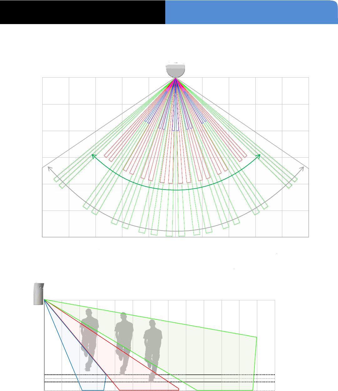
Detection diagrams
Technical data subject to change without notice.
0
2m
4m
6m
8m
10m
12m
5m 4m 3m 2m 1m 0 1m 2m 3m 4m 5m
PIR angle = 90°
Camera angle = 110°
Horizontal distance
Floor
level
0m 1m 4m 8m 12m
Mounting at 2m10
Mounting at 2m30
1m00

IMV Indoor Motion Viewer - Install sheet Ed05EN
4/5
Indoor Motion Viewer IMV
INSTALLATION DATA SHEET
(FR) Notes de sécurité / (EN) Security notes / (DE) Hinweise zur Sicherheit
Français
English
Deutsch
Retirez les piles avant toute opération de
maintenance !
Attention ! Il y a un risque d'explosion si
l'une des piles utilisées est remplacée par
une pile de type incorrect !
Respectez la polarité lors de la mise en
place des piles !
Ne jetez pas les piles usagées ! Ramenez-
les à votre installateur ou à un point de
collecte spécialisé.
Remove battery before any maintenance!
WARNING, there is a risk of explosion if a
battery is replaced by an incorrect type!
Observe polarity when setting up the
batteries!
Do not throw used batteries! Bring them to
your installer or a collection point.
Batterien vor jeglichen Wartungsarbeiten
entfernen!
Vorsicht, es besteht Explosionsgefahr,
wenn eine Batterie durch eine Batterie
falschen Typs ersetzt wird!
Achten Sie beim Einsetzen der Batterien
auf die Polung!
Entsorgen Sie Batterien nicht im normalen
Haushaltsmüll! Bringen Sie Ihre
verbrauchten Batterien zu den öffentlichen
Sammelstellen.
FCC Regulatory Information for USA and CANADA
FCC Part 15.21 Changes or modifications made to this equipment not expressly approved by RSI VideoTechnologies may void the
FCC authorization to operate this equipment.
FCC Part 15.105 Class B
This equipment has been tested and found to comply with the limits for a Class B digital device, pursuant to Part 15 of the FCC
Rules. These limits are designed to provide reasonable protection against harmful interference in a residential installation. This
equipment generates, uses and can radiate radio frequency energy and, if not installed and used in accordance with the
instructions, may cause harmful interference to radio communications. However, there is no guarantee that interference will
not occur in a particular installation. If this equipment does cause harmful interference to radio or television reception, which
can be determined by turning the equipment off and on, the user is encouraged to try to correct the interference by one or
more of the following measures:
• Reorient or relocate the receiving antenna.
• Increase the separation between the equipment and receiver.
• Connect the equipment into an outlet on a circuit different from that to which the receiver is connected.
• Consult the dealer or an experienced radio/TV technician for help.
Radio frequency radiation exposure information according 2.1091 / 2.1093 / OET bulletin 65
This equipment complies with FCC radiation exposure limits set forth for an uncontrolled environment. This equipment should
be installed and operated with minimum distance of 20 cm between the radiator and your body.
This transmitter must not be co-located or operating in conjunction with any other antenna or transmitter.
This device complies with Part 15 of the FCC Rules and with RSS-210 of Industry Canada.
Operation is subject to the following two conditions:
(1) This device may not cause harmful interference, and
(2) This device must accept any interference received, including interference that may cause undesired operation.
Cet appareil est conforme à la Partie 15 des règlementations de la FCC et avec la norme RSS-210 de l'Industrie Canadienne.
Son fonctionnement est soumis aux deux conditions suivantes :
(1) Cet appareil ne doit pas causer d'interférences nuisibles et
(2) Cet appareil doit accepter toute interférence reçue, y compris les interférences pouvant entraîner un fonctionnement
indésirable.
IMV Indoor Motion Viewer - Install sheet Ed05EN
5/5
Indoor Motion Viewer IMV
INSTALLATION DATA SHEET
Properties
Panel compatibility ....................... XL, XT, XV, XTiP, VISIO
Power ........................................................................ Type C
Nominal voltage .................................................... 3,6V
Low voltage limit ...................................................... 3V
Battery type ................ AA lithium 3,6V, SAFT LS14500
Battery quantity ........................................................... 2
Battery life ................................................ up to 4 years
Current consumption (standby / max)
IMV200 (868MHz) ................ (57 µA / 160 mA)
IMV601 (915MHz) ................ (72 µA / 180 mA)
IMV701 (920MHz) ................ (72 µA / 180 mA)
RF technology ......................... S²View® Radio bidirectional
Central frequency
868MHz on IMV200 (Europe, South Africa, Asia)
915MHz FHSS on IMV601 (USA, Canada, South America)
920MHz FHSS on IMV701 (Australia, South America)
Transmission Security ......... AES Algorithm encryption
Supervision ............................................................ 8mn
Antenna ........................................................ integrated
Camera
Angle ..................................................................... 110°
Sensor type ........................................................ CMOS
Daylight vision ............... Color (programmable to B&W)
Night vision ............................ automatic Infra-red B&W
IR illumination ..................... automatic with 2x IR LEDs
IR Illumination distance ........................... up to 7m/23ft
Video
Video formats .................. MJPEG-WMV, MJPEG-DIFF
Frequency .............................................................. 5i/s
Video length .......................................... Programmable
..........................Default value: 7s (IMV601 & IMV701) or 10s (IMV200)
Resolution ............................................. QVGA (320x240)
Quality ........................................................... SQ or HQ
Typical file size ................................................ ~220Ko
Snapshot
Format ........................................................... JPEG
Resolution ............. QVGA (320x240) or VGA (640x480)
Quality ........................... HQ (programmable to SQ)
Typical file size ................................................ 8Ko
PIR performances
Detection angle ................................................. 90°
Distance .................................................... 12m/40ft
Sensibility ..... Programmable to 5 predefined levels
Tamper
Cover and wall tamper
Tests Detection test (walk test) ..... Yes with LED indicator
RF test .............................................................. Yes
Installation / Mounting
Mounting height ......................... 2m10 to 2m30 / 6.9 to 7.5ft
Mounting on wall:
On flat wall ....................................... with 2x screws
In corner ........................................... with 2x screws
Closing of the casing ...............................................................
Closing by clip or with screw if required by local
legislation.
Environmental and Physical properties
Temperature ......................................... -10°/+50°C (+14°F/+122°F)
Relative humidity ...................................... 90%, non-condensed
IP level ...................................................................... IP30 / IK04
Material .................................................. ABS type ULV0 - White
Sizes .................................................. (HxWxT) 98 x 52 x 40mm
(HxWxT) 3.86 x 2.05 x 1.57 inches)
Weight ........................................ 60gr (2.12oz) (without batteries)
Certifications & standards
868MHz (IMV200 for Europe, South Africa and Asia)
Standards:
EN60950-1:2006+/A11:2009+/A1:2010
EN300220-1 V2.4.1
EN300220-2 V2.4.1
NF EN50130-4:1995+/A1:1998+/A2:2003;
NF EN50130-5:1998 Class II
NF EN50131-2-2:2009 - Grade 2
NF EN50131-5-3:2005 - Grade 2
NF EN50131-6:2008 Grade 2 –Type C
Certifications
Europe CE / EN50131 Grade 2
Netherlands NCP
Singapore IDA
South Africa ICASA
915MHz (IMV601 for USA, Canada and South America)
Certifications:
USA FCC Part15C (FCC47 CFR part15)
Canada IC (RSS-210 Issue 8)
920MHz (IMV701 for Australia and South America)
Certifications:
Australia C-Tick (AS-NZS4268)
EMEA Sales
23, avenue du Général Leclerc
92340 BOURG-LA-REINE
FRANCE
Hot line: +33 (0)820.846.62
Fax: +33 (0)3.88.29.04.00
North American Headquarters
RSI Video Technologies, Inc.
1375 Willow Lake Blvd. #103
Vadnais Heights, MN 55110
USA
Hot line: 877-206-5800
Fax: +1 (651)-762-4693
www.videofied.com
© 2013 RSI Video Technologies. Videofied® is a trademark registered by RSI Video Technologies. Content and specifications subject to change without notice.