RSI VIDEOTECHNOLOGIES WP02 Alarm Panel User Manual Manual
RSI VIDEOTECHNOLOGIES Alarm Panel Manual
UserManual.wiki
>
RSI VIDEOTECHNOLOGIES
>
WP02 User Manual
Manual
Navigation menu
Upload a User Manual
Namespaces
Wiki Guide
HTML
PDF
Info
Views
User Manual
Discussion / Help
Navigation
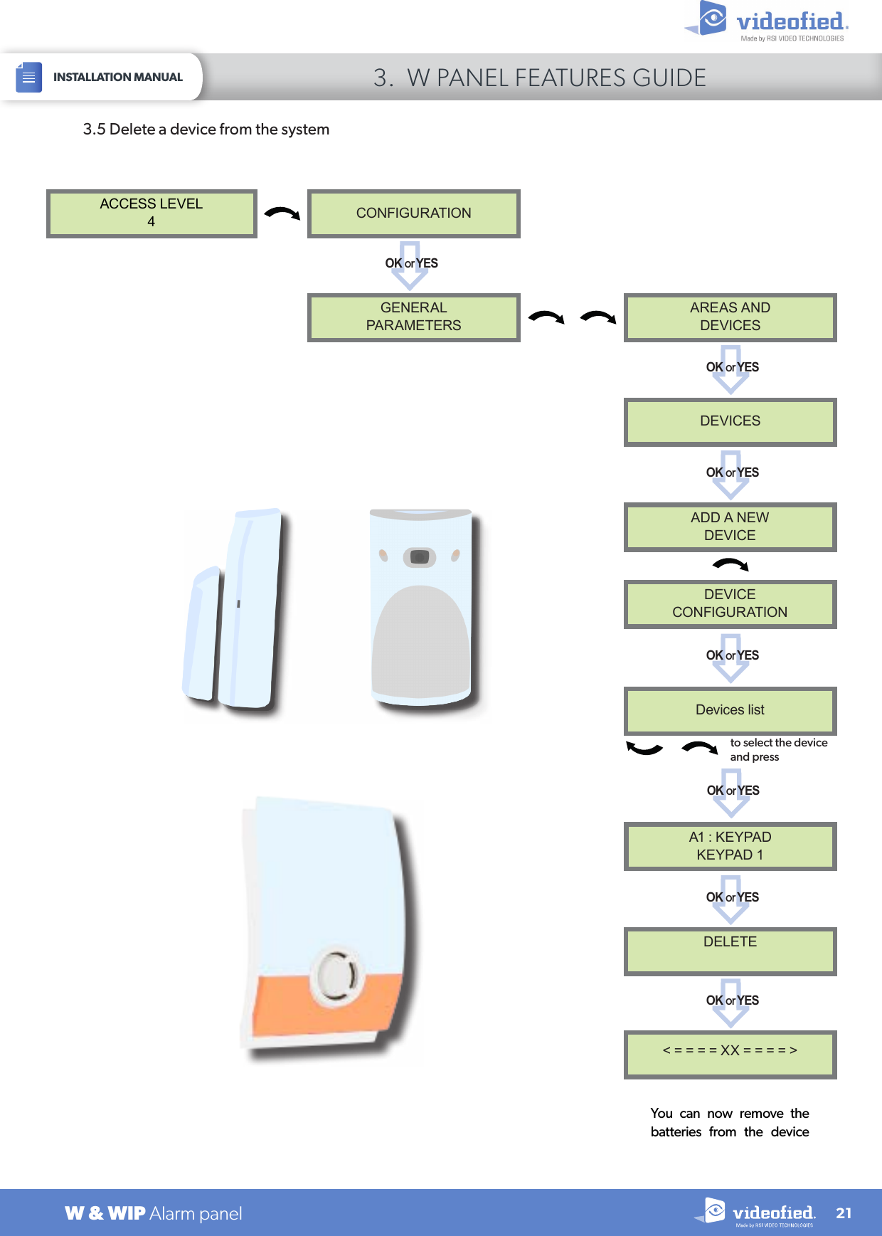
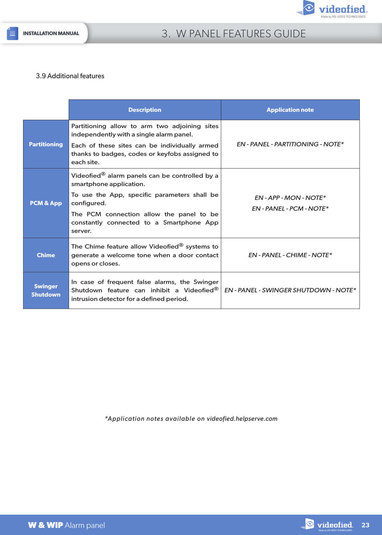
![223. W PANEL FEATURES GUIDEINSTALLATION MANUALW & WIP Alarm panelWhen the user disarms the system, the keypad indicates the last event. In case of the user needs to read the full log file, use the keypad to go in EVENT LOG, press OK or YES on SELECT LAST EVENTS and use arrow to list the events.3.6 Read the event logPress OK or YES for more information about an eventEVENTLOGSELECT LAST EVENTSOK or YES 15/10/13 11:29MODIFIED PARAMETOK or YES 15/10/13 11:10SYSTEM DISARMED3.8 Golden rulesArea 1 device are delayed by default (Area mode parameter set as Auto). When you register a keypad or a badge reader into an area set as Auto, that area will automatically be delayed.Never position a panel next to a high voltage electrical cabinet. The interference will affect radio and 2G3G performance.Press CLR to erase a typing mistake.Never register the same device twice (delete from the system first).The panel can register of up to 25 devices of all types, including the keypad and the keyfobs.Follow the Motionviewer installation instructions. Consider the infrared field of detection when installing the Motionviewer cameras, in order to protect goods or an entry point instead of a zone.1.2.3.4.5.6.Do not fix the keypad at the beginning of the installation as it will need to be portable during programming.Always clean the lens of the cameras aer the installation. Use a clean, dry cloth, taking care not to exert pressure on the lens.Internal components are fragile, be careful opening or closing the panel.LCD screen goes dark aer 30 seconds of inactivity, press an arrow or numeric key to light it up.Infrared detectors should never be installed in stairs or close to stairs (false alarm risks).A colon display [:] means that the parameter can be changed. Press OK / YES to display the colon7.8.9.10.11.12.3.7 Automatic arming/disarmingScheduling: This feature arms or disarms the system automatically at a defined hour and weekday. The scheduling feature description is available in the EN- PANEL - SCHEDULING - NOTE application note (available on videofied.helpserve.com).Autoarming Delay: Defines an automatic rearming after every system disarming. Once the delay has expired, the panels arms automatically. Enter 0 to disable the feature.](https://usermanual.wiki/RSI-VIDEOTECHNOLOGIES/WP02/User-Guide-3446311-Page-22.png)