RSI VIDEOTECHNOLOGIES XT04 XTIP631 User Manual InstallationInstructions
RSI VIDEOTECHNOLOGIES XTIP631 InstallationInstructions
Contents
- 1. InstallationInstructions.pdf
- 2. UserManual.pdf
InstallationInstructions.pdf
www.videofied.com
Security
With two modes of transmission, Ethernet and Cellular (3G), the
XT-IP630 panel ensures maximum safety. In case of Ethernet
connection loss, the XT-IP630 panel will switch to cellular (3g)
(if enabled) to transmit alarms and videos.
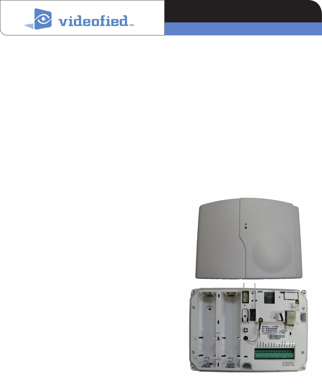
Description
The XT-IP630 control panel is a wireless, battery operated,
hybrid alarm system. It is designed for residential, small
business security applications, as well as both indoor and
outdoor commercial applications (construction sites, cell
towers, remote sites, substations...) where the location of the
panel has Ethernet (IP) or Cellular (3G) connection.
Features
The panel includes the choice of many different configuration
options including the following:
> Arming by Videofied Peripherals, Schedule, Virtual Keypad,
or exisiting alarm system.
> Power the system by Power Supply + Battery Backup or
standalone battery (up to 4 years).
> Communicate over Ethernet + Cellular Backup (3G),
Ethernet Only, or Cellular Only (3G).
> 25 wireless zones for Videofied Peripherals plus 3
Programmable input zones for hardwired devices.
> Choose between the Internal RF antenna or switch to an
External RF antenna option.
> 2 Hardwired outputs.
> Virtual Keypad arming and disarming from Smartphone.
Supervised Wireless Technology
The XT-IP630, along with all Videofied devices, utilize patented
S2View® - Spread Spectrum, AES Encrypted Wireless
technology, providing optimum signal integrity and security.
Bi-directional RF communication paths between all system
devices and the system control panel assure high signal
reliability. Integrated RF and Cellular connections allow for
addition of external antennas for increased performance.
The panel supervises every device (excluding the remote
keyfob) to validate current open/close state, tamper condition,
serial number, date of manufacture, firmware revision, and
battery status.
* When using the XT-IP630 panel with the Ethernet connection or SMS Arming you
must use a 12v 2A Power Supply with 4 Alkaline battery backup (PP4)*
PRODUCT SPECIFICATIONS SHEET
Control Panel XT-IP630
Made by RSI VIDEO TECHNOLOGIES 2327-XT-IPSP February 2013
www.videofied.com
Control Panel Videofied XT-IP630
Features
> Video Verification - video resolution of 320 x 240 pixels, 0
lux sensitivity, 5-frames per second for approx. 10 seconds
total recording time. 220K MPEG file.
> Up to 25 Wireless zones/devices
> Mapping feature to trigger a video upon activation of a
programmable input
> 3 programmable inputs
> 2 programmable outputs to activate third party devices on
site (smoke cloak, gates, strobes, sirens, etc...)
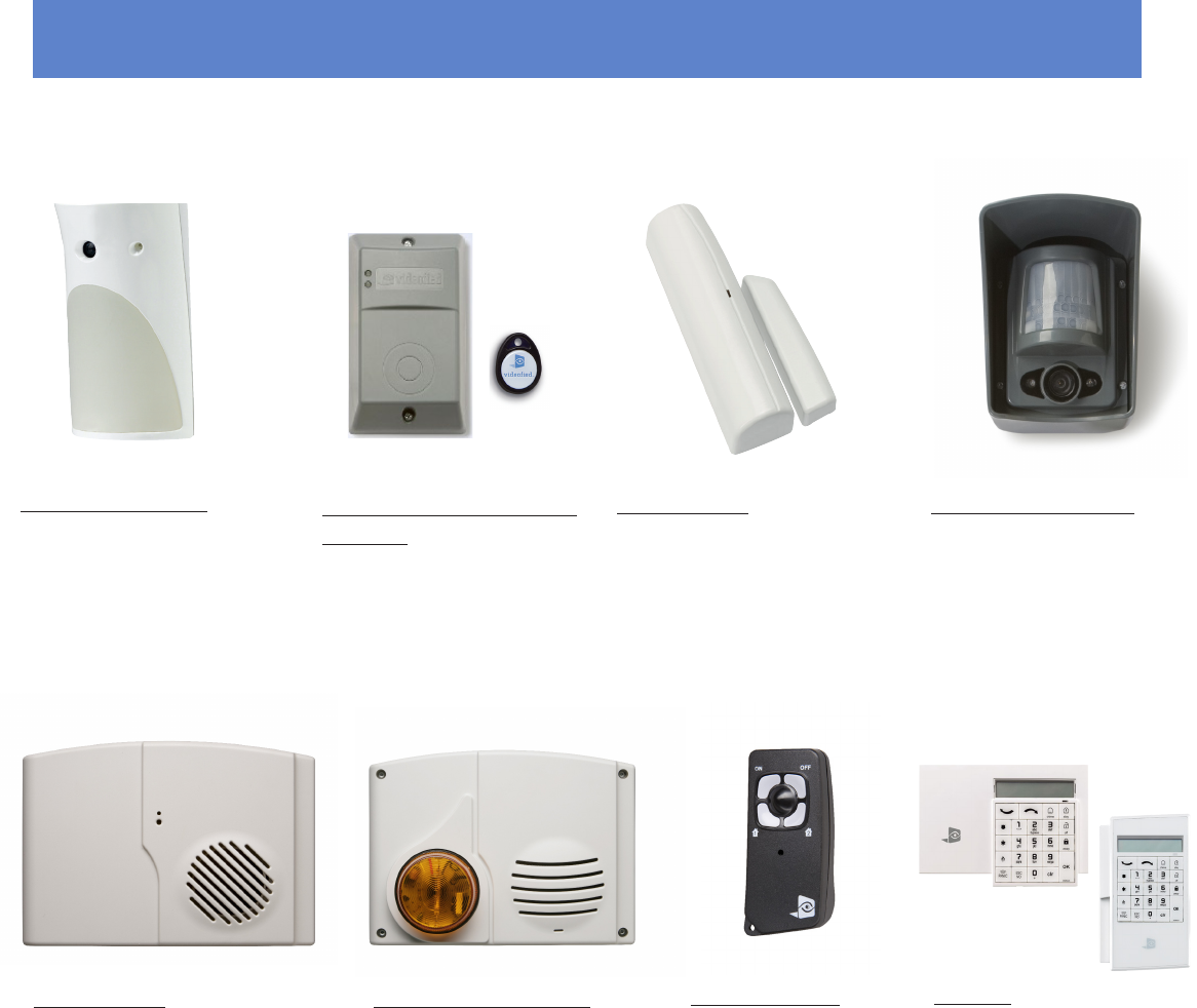
Compatibility The XT-IP630 works with all the following Videofied wireless devices:
Outdoor Badge Reader with
Prox-Tag - Allowing Arming/
disarming of the system from
outside the premices. The
Prox-Tags are standard Mifare
badges.
Remote Keyfobs - allow
limited system operation
and panic alarm
capability in a portable,
convenient package.
Indoor MotionViewer -
integrated PIR motion
detector, night vision digital
camera, infrared illuminators.
MotionViewers detect intruders
and capture a 10 second video
of the intrusion which is sent to
the panel over RF.
Door Contacts - detect door
and window open/close activity.
Interior Sirens - provide status
beeps and alarm sounds
throughout the premises where
needed.
Exterior Sirens/Strobes -
provide alarm sounds and
visual identification of alarm
site for responding authorities.
> 2 dedicated on-board connectors to extend the 3G
coverage and the radio coverage
> 4 Areas with 2 special arming mode and partitions
> 20 user codes or Badges
> 4.000 Events history log
> Power : 12VDC with Alkaline batteries for back-up (up to
one month of back-up)
> Built-in RJ45 for Ethernet transmission to report to your
Monitoring Station in the Frontel protocol
> Built-in 3G cellular transmitter to report to your Monitoring
Station in the Frontel protocol
Outdoor MotionViewer
- integrated PIR motion
detector, night vision digital
camera, infrared illuminators.
MotionViewers detect intruders
and capture a 10 second video of
the intrusion which is sent to the
panel over RF.
Keypads - For arming/
disarming, programming,
and maintenance.
Properties
Power Requirements (Option 1) Must be used when using
Ethernet Communication or SMS- 12v DC / 2A
Back up 4 Alkaline 1.5v DCell, LR20
Battery life (estimated) Up to 1 year
Power Requirements (Option 2) - Will not work with Ethernet
or SMS- 4 SAFT LSH20 Batteries
Battery life Up to 4 years
RF Technology: S2View®
Radio type Spread Spectrum Bidirectional
Operating frequency 915 MHz. (US)
Transmission security AES encryption algorithm
Supervision Panel polls devices every 8 minutes
Antennas Integrated
Tamper:
Base and Cover Tamper
Wired Arming Inputs: 2
Dry Contact option Yes
Inputs Voltage 2VDC (15v max)
Inputs Current 2 mA max
Programmable Wired Inputs: 3
Dry Contact Yes
Inputs voltage 12VDC (15v max)
Programmable Wired Outputs: 2
Max switching voltage 220VDC / 250VAC
Max switching current 4A
Max switching power 120VA
Programming: Alphanumeric Keypads
or Frontel Installer Software
Devices per system:
24 per system + Programming/Maint. Keypad
Access Codes 19 maximum + Installer Code
Security Levels 3
Arming modes 2
Areas: 4 (area1 predefined from factory
entry/exit delayed. Areas 2,3 & 4 programmable)
Communication Formats Cellular 3G / Ethernet
Protocols Frontel Only
Installer Codes One (for system programming only
Special arming modes 4 (Area 1 predefined
Communication Formats IP
Communicator type Cellular 3G and Ethernet
IP Stack IP, TCP/IP
Remote Maintenance Frontel Installer Protocol only
Video Transmission By Frontel protocol to
Central Monitoring Station
Video file size 220 Kbytes
Video Framing 5 frames/second
Image format JPEG
Image Resolution 320x240 Pixels
History/Event Log 4,000 Stored events
Physical Data
Operating temperature 14° to +104° F (-10 to +40° C)
Maximum relative humidity 95%, non-condensing
Material ABS-ULVO
Dimensions (LxWxD) 9” x 7”x 2-1/16”
22.86 x 17.78 x 5.48cm
Installation/Mounting
Control Panel/Base: Two srews sec u re s cont ro l pa n e l
cover to base. Three screws
secure control panel base to wall
External Antenna:
2 Built in MMCX connectors to extend the 3G and RF range
www.videofied.com
PRODUCT SPECIFICATION SHEET
Control Panel XT-IP630

PRODUCT SPECIFICATION SHEET
Control Panel XT-IP630
EMEA SALES
23, avenue du Général Leclerc
92340 BOURG-LA-REINE
FRANCE
Hotline: +33 (0)820 846 620
Fax: +33 (0)1 82 69 80 10
© 2011 RSI VIDEO TECHNOLOGIES. VIDEOFIED® is a Registered Trademark of RSI VIDEO TECHNOLOGIES.
S2View® is a registered trademark of RSI VIDEO TECHNOLOGIES. Specications subject to change without notice.
USA SALES
1375 Willow Lake Blvd. #103
Vadnais Heights, MN 55110
USA
Hotline: +1 877 206 5800
Fax: +1 651 762 4693
www.videofied.com
FCC Regulatory Information for USA and CANADA
FCC Part 15.21 Changes or modifications made to this equipment not expressly approved by RSI VideoTechnologies may void the FCC
authorization to operate this equipment.
FCC Part 15.105 Class B
This equipment has been tested and found to comply with the limits for a Class B digital device, pursuant to Part 15 of the FCC Rules.
These limits are designed to provide reasonable protection against harmful interference in a residential installation. This equipment
generates, uses and can radiate radio frequency energy and, if not installed and used in accordance with the instructions, may
cause harmful interference to radio communications. However, there is no guarantee that interference will not occur in a particular
installation. If this equipment does cause harmful interference to radio or television reception, which can be determined by turning the
equipment off and on, the user is encouraged to try to correct the interference by one or more of the following measures:
• Reorient or relocate the receiving antenna.
• Increase the separation between the equipment and receiver.
• Connect the equipment into an outlet on a circuit different from that to which the receiver is connected.
• Consult the dealer or an experienced radio/TV technician for help.
Radio frequency radiation exposure information according 2.1091 / 2.1093 / OET bulletin 65
This equipment complies with FCC radiation exposure limits set forth for an uncontrolled environment. This equipment should be
installed and operated with minimum distance of 20 cm between the radiator and your body.
This transmitter must not be co-located or operating in conjunction with any other antenna or transmitter.
This device complies with Part 15 of the FCC Rules and with RSS-210 of Industry Canada.
Operation is subject to the following two conditions:
(1) This device may not cause harmful interference, and
(2) This device must accept any interference received, including interference that may cause undesired operation.