RSI VIDEOTECHNOLOGIES XT05 LAN Alarm panel User Manual
RSI VIDEOTECHNOLOGIES LAN Alarm panel Users Manual
UserManual.wiki
>
RSI VIDEOTECHNOLOGIES
>
XT05 User Manual
Users Manual.pdf
Navigation menu
Upload a User Manual
Namespaces
Wiki Guide
HTML
PDF
Info
Views
User Manual
Discussion / Help
Navigation

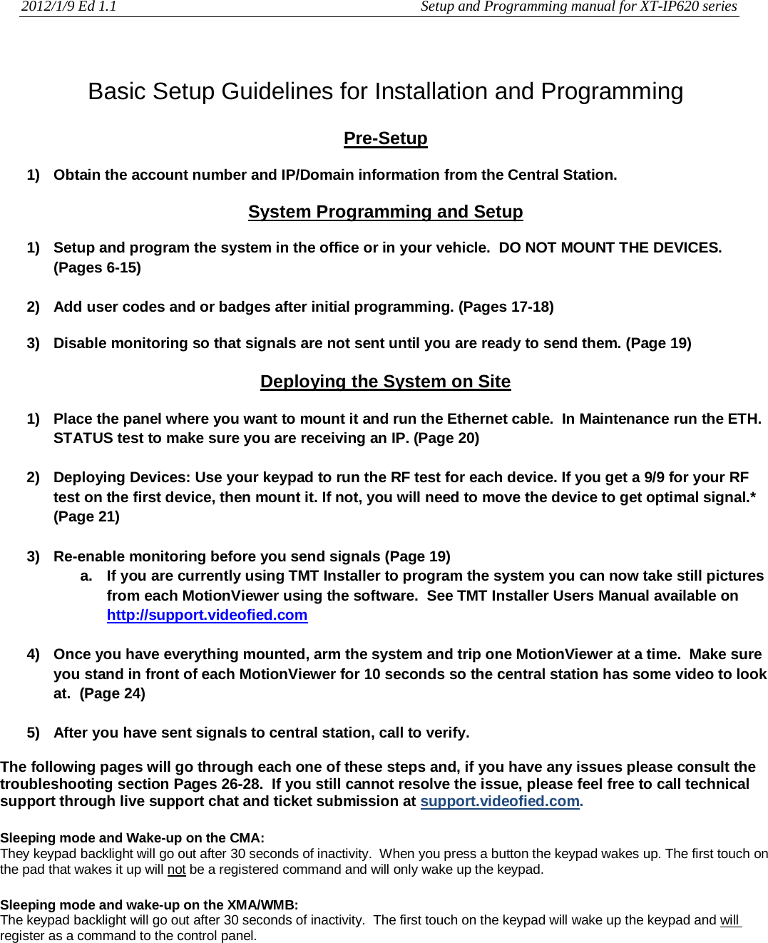

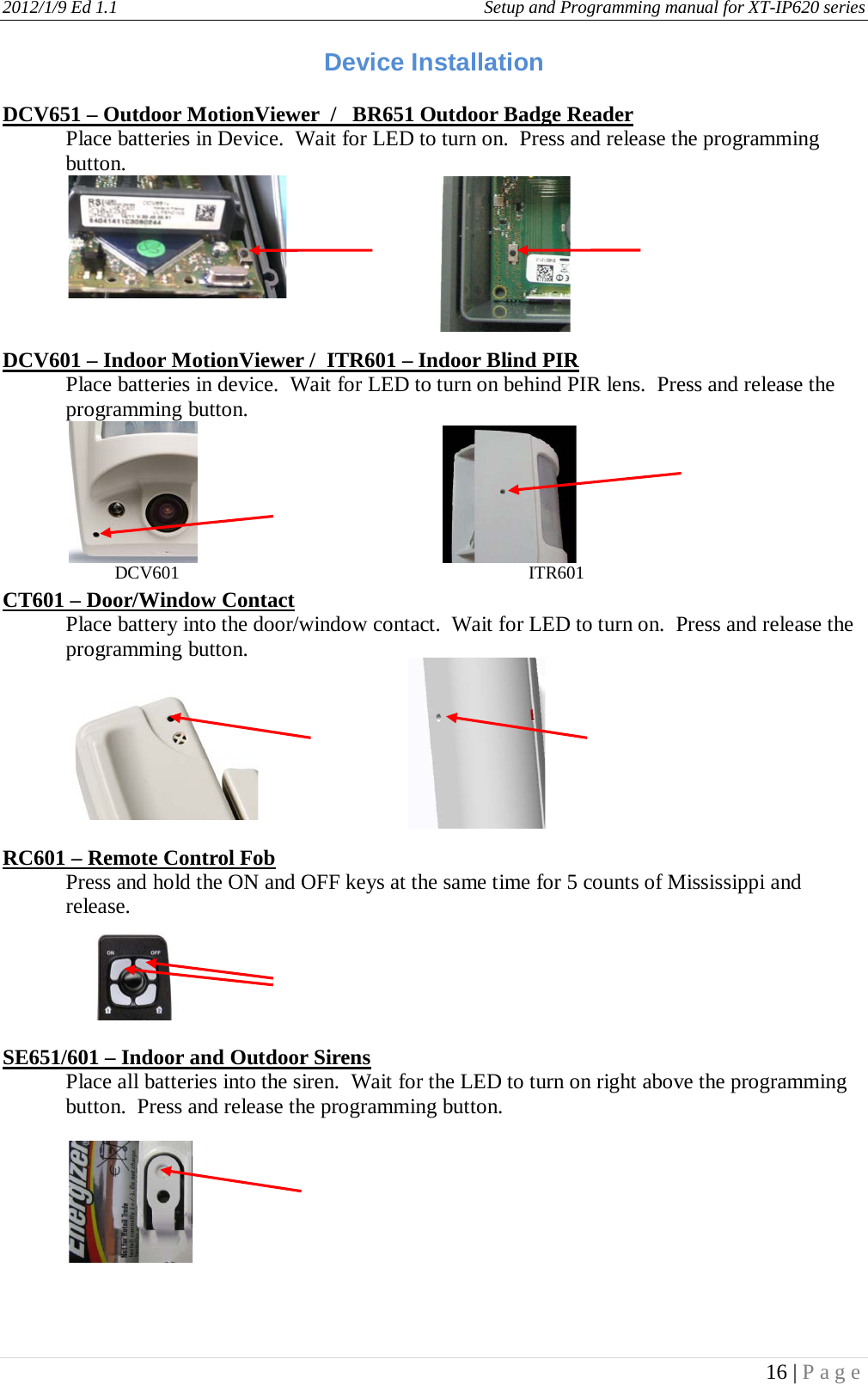
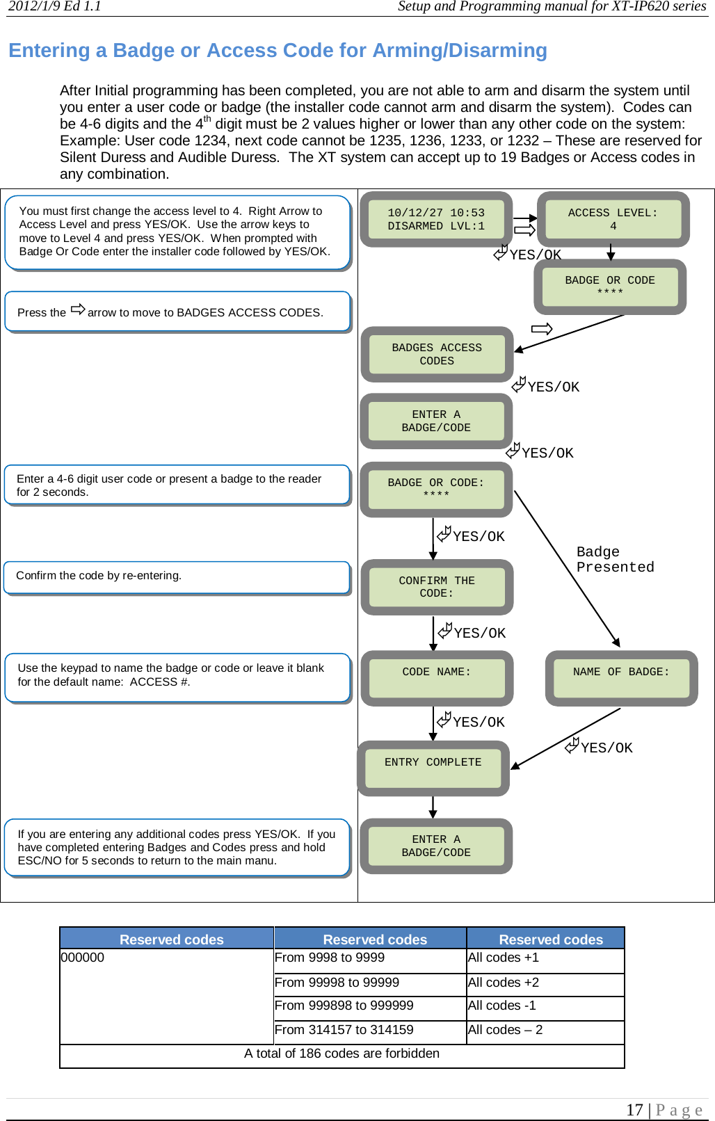
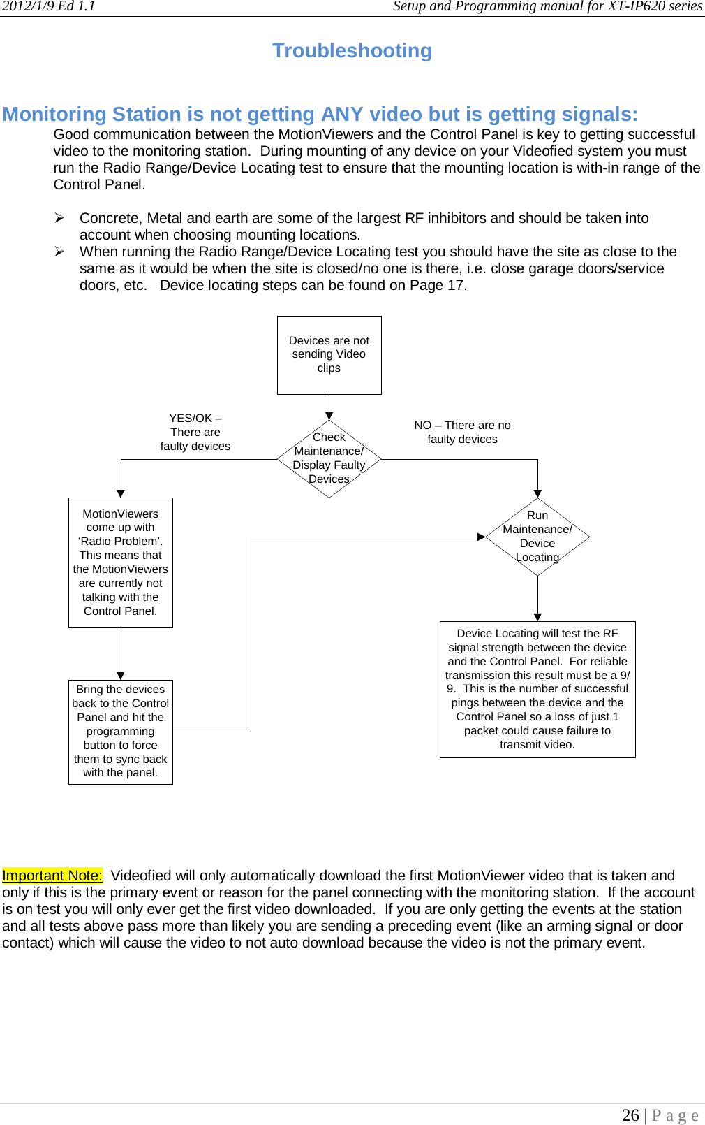
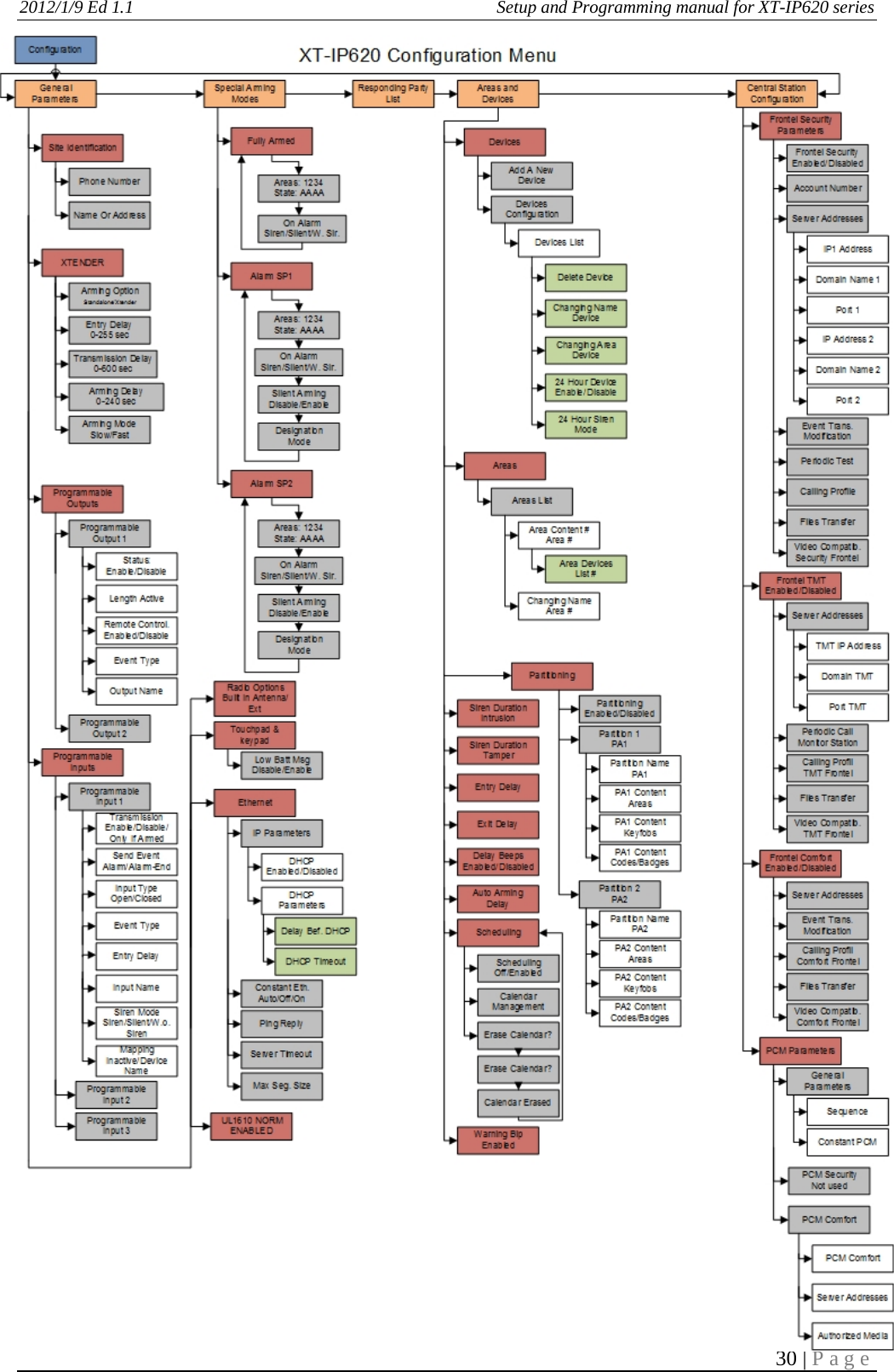
![2012/1/9 Ed 1.1 Setup and Programming manual for XT-IP620 series 18 | Page Access level Definition & rights LVL1 Stand by level LVL2 Restricted USER level where it is only possible to arm/disarm the system. LVL3 USER level where it is possible to arm/disarm the system, check the event log, test the devices. Modifications of the setting are not possible at this level. User LVL3 can create LVL3 or LVL2 access codes. LVL4 INSTALLER level where it is possible to modify the setup of the panel. The approval of a LVL3 or LVL2 is required to modify the level for LVL4. Installer LVL4 can create the first LVL3 access code only. Configuration of Special Arming Modes: A Armed D Disarmed P Perimeter Devices Only (devices must be programmed) E External Devices Only (devices must be programmed) Siren Immediate triggering of all sirens Delay beeps Entry/Exit delay beeps, then triggering of the sirens Silent No Sirens, No Beeps Without Siren Beeps on the keypad only To configure or modify a special arming mode, with the direction arrow go to the menu: CONFIGURATION (LEVEL 4) + [YES/OK] ALARM MODES PROGRAMMABLE + [YES/OK] FULLY ARMED, SP1 and SP2 (use direction arrows to select the arming mode you want to modify + [YES/OK]). For each arming mode, it is possible to specify how each of the 4 areas will be armed and how the system will behave during an alarm. Areas: 1 2 3 4 press the corresponding number to change that areas arming option States: A A A A state for the respective area. Press the [YES/OK] key after this configuration step. The system will then display what siren mode will be in effect for this special profile. Select the siren mode using the direction arrows then press [YES/OK].](https://usermanual.wiki/RSI-VIDEOTECHNOLOGIES/XT05/User-Guide-2257722-Page-18.png)
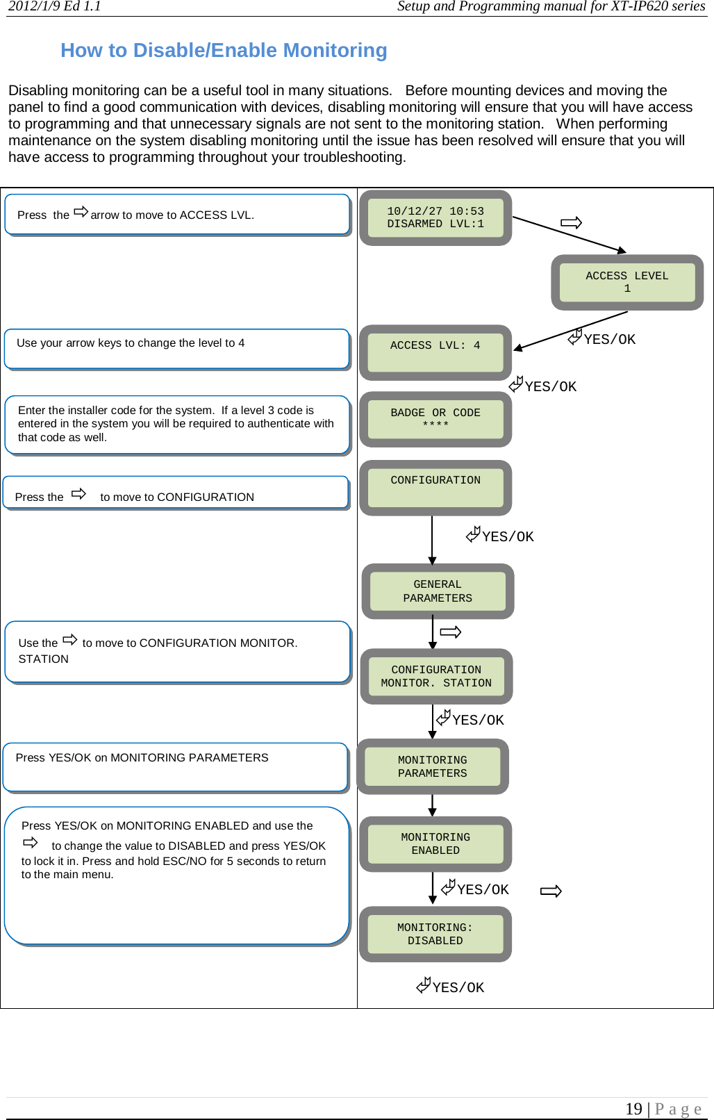
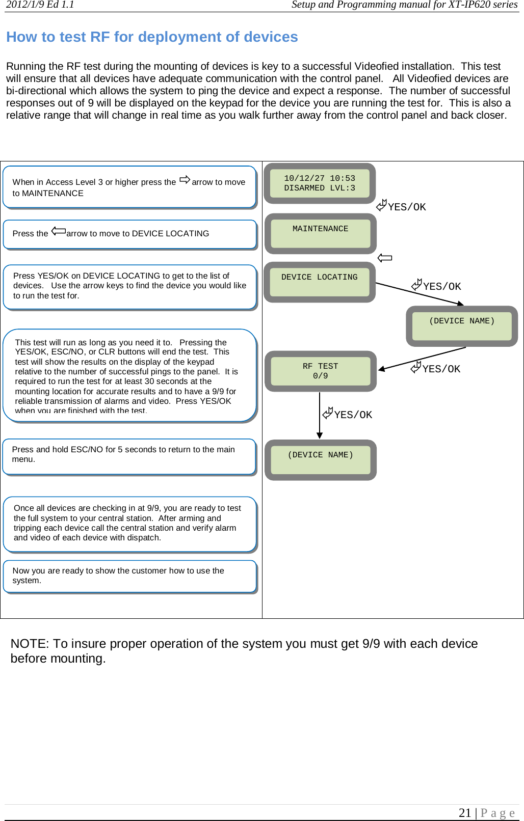
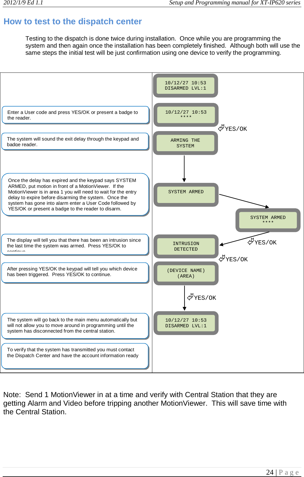
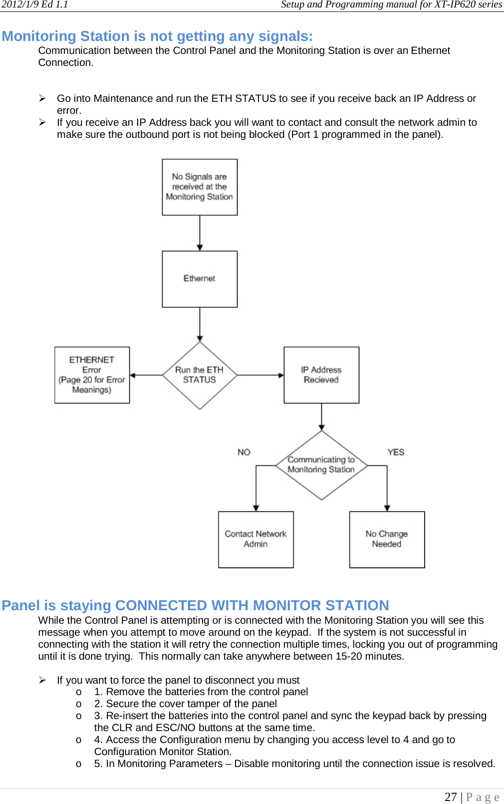
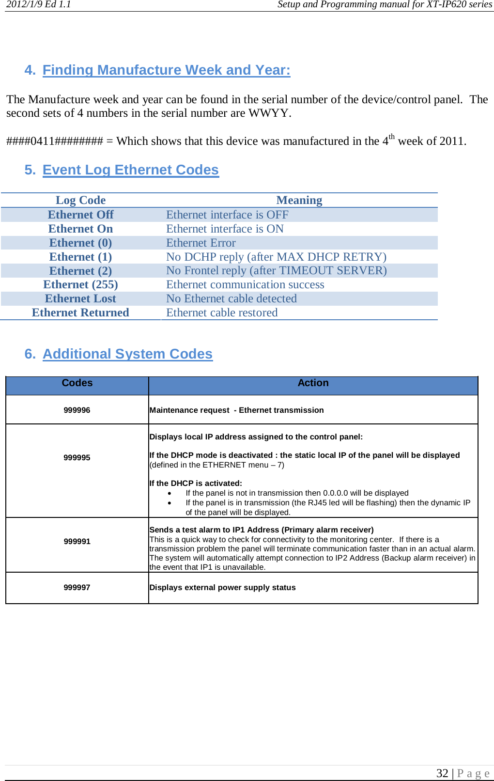
![2012/1/9 Ed 1.1 Setup and Programming manual for XT-IP620 series 20 | Page ETHERNET Parameters: nging Siren Options After initial programming has been completed any sounder on the system will be enabled by default, this includes the sounder on the Keypad and Badge Reader. While there is no way to disable the sounding of the exit delay you are able to disable the intrusion sound. How to test to the dispatch center Testing to the dispatch is done twice during installation. Once while you are programming the system and then again once the installation has been completely finished. Although both will use the same steps the initial test will be just confirmation using one device to verify the programming. How to Disable Monitoring Disabling monitoring can be a useful tool in many situations. Before mounting devices and moving the panel to find a good 2G3G level, disabling monitoring will ensure that you will have access to programming and that unnecessary signals are not sent to the monitoring station. When performing maintenance on the system disabling monitoring until the issue has been resolved will ensure that you will have access to programming throughout your troubleshooting. To configure or modify Ethernet Parameters, go to: CONFIGURATION (level 4) + [YES/OK] >> GENERAL PARAMETERS + [YES/OK] >> ETHERNET + [YES/OK] • IP Parameters: 1. DHCP Enable – IP address is assigned by the DHCP service on the network. 2. DHCP Disable – IP address must be defined in Ethernet parameters. IP address will NOT be automatically obtained from DHCP service on the network. • Constant Ethernet: 1. “Auto” Mode - We recommend this mode. If main powered, the panel will be connected constantly to the local Network. In case of an alarm, the alarm will be sent in few seconds to the monitoring station. When the main power is cut, the Ethernet module will switch off after a delay (DELAY BEFORE OFF – 30 by default) in order to save battery life. In case of an alarm, the panel will at first connect to the local Network. It adds few seconds to the total process of sending an alarm. 2. “ON” Mode - The panel will be connected constantly to the local Network. This option will impact back-up battery life. 3. “OFF” Mode - For each transmission of alarm and video, the panel will connect to the local Network. • PING REPLY: Enables ping response • Time Out Server: In case of disconnection to the local Network, the panel will try after that time to re-connect. • Max Seg. Size: Size of packet sent Codes Action 999996 Maintenance request - Ethernet transmission 999995 Displays local IP address assigned to the control panel: If the DHCP mode is deactivated : the static local IP of the panel will be displayed (defined in the ETHERNET menu – 7) If the DHCP is activated: • If the panel is not in transmission then 0.0.0.0 will be displayed • If the panel is in transmission (the RJ45 led will be flashing) then the dynamic IP of the panel will be displayed. 999991 Sends a test alarm to IP1 Address (Primary alarm receiver) This is a quick way to check for connectivity to the monitoring center. If there is a transmission problem the panel will terminate communication faster than in an actual alarm. The system will automatically attempt connection to IP2 Address (Backup alarm receiver) in the event that IP1 is unavailable. 999997 Displays external power supply status](https://usermanual.wiki/RSI-VIDEOTECHNOLOGIES/XT05/User-Guide-2257722-Page-20.png)