RSIAlarm CE00 central of an alarm system User Manual Product Catalog
RSIAlarm central of an alarm system Product Catalog
RSIAlarm >
Users Manual
Installation
Manual
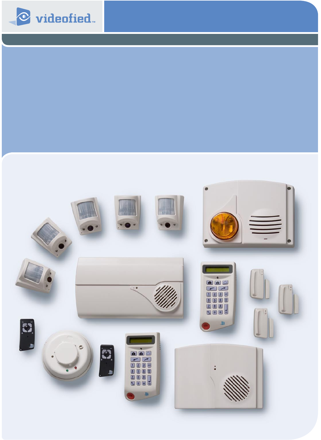
VIA-PRO Security System
Manufactured by RSIalarm Document No. 2012 June 2007
Regulatory Information
FCC Part 15 Information to the User Changes or modications not expressly
approved by RSIalarm, Inc. can void the user’s authority to operate the equipment.
FCC Part 15 Class B This equipment has been tested and found to comply with
the limits for a Class B digital device, pursuant to part 15 of the FCC Rules. These
limits are designed to provide reasonable protection against interference in a
residential installation.
This equipment generates, uses, and can radiate radio frequency energy and, if
not installed and used in accordance with the instructions, may cause harmful
interference to radio communications. However, there is no guarantee that
interference will not occur in a particular installation.
If this equipment does cause harmful interference to radio or television reception,
which can be determined by turning the equipment off and on, the user is encour-
aged to try to correct the interference by one or more of the following measures:
• Reorient or relocate the receiving antenna.
• Increase the separation between the equipment and the receiver.
• Connect the affected equipment and the panel receiver to separate AC power
outlets, on different branch circuits.
• Consult the dealer or an experienced radio/TV technician for help.
ACTA Part 68 This equipment complies with Part 68 of the FCC Rules and the
requirements adopted by the ACTA. Located on this equipment is a label that
contains, among other information, the registration number and the ringer
equivalence number
(REN) for this equipment. If requested, this information must be provided to
the telephone company. The REN for the panel is 3.6”.
Registration No. US:
The REN is used to determine the maximum number of devices that may be con-
nected to your telephone line. Excessive RENs on a telephone line may result in
devices not ringing in response to an incoming call. In most areas, the sum of all
device RENs should not exceed ve (5.0). To be certain of the number of devices
that may be connected to a line, as determined by the total RENs, contact the local
telephone company. For products approved after July 23, 2001, the REN for this
product is part of the product identier that has the format US:AAAEQ##TXXXX.
The digits represented by ## are the REN without a decimal point (e.g. 02 is a REN
of 0.2). For earlier products, the REN is separately shown on the label.
A plug and a jack used to connect this equipment to the premises wiring
and telephone network must comply with the applicable FCC Part 68 Rules and
requirements as adopted by ACTA. A compliant telephone cord and modular
plug is provided with this product. It is designed to be connected to a compliant
modular jack. See the Installation Manual for details.
Alarm dialing equipment must be able to seize the telephone line and place a
call in an emergency situation. It must be able to do this even if other equipment
(telephone, answering machine, computer modem, etc.) already has the telephone
line in use. To do so, alarm dialing equipment must be connected to a properly
installed RJ31X jack that is electrically in series and ahead of all other equipment
connected to the same telephone line. Proper installation is depicted in the fol-
lowing diagram. If you have any questions concerning these instructions, consult
with your local telephone company or a qualied installer about installing a RJ31X
jack and alarm dialing equipment for you.
If this equipment causes harm to the telephone network, the telephone company
may temporarily disconnect your service. If possible, you will be notied in advance.
When advance notice is not practical, you will be notied as soon as possible.
The telephone company may make changes in its facilities, equipment,
operations, or procedures that could affect the operation of the equipment.
The telephone company may ask you to disconnect the equipment from the
network until the problem has been corrected, or you are sure that the
equipment isnot malfunctioning.
This equipment may not be used on coin service provided by the telephone
company. Connection to party lines is subject to state tariffs.
This device complies with Part 15 of the FCC Rules. Operation is subject to the
following two conditions: (1) this device may not causeharmful interference, and
(2) this device must accept any interferencereceived, including interference that
may cause undesired operation.
RF Exposure Warning: During operation, the user has to keep a minimum
separation distance of 20 cm with the RF devices.
For Canada:
Le présent matériel est conforme aux spécications techniques applicables
d’Industrie Canada.
L’utilisation de ce dispositif est autorisée seulement aux conditions suivantes :
(1) il ne doit pas produire de brouillage et (2) l’utilisateur du dispositif doit étre prét é
accepter tout brouillage radioélectrique reçu, méme si ce brouillage est susceptible
de compromettre le fonctionnement du dispositif.
L’indice d’équivalence de la sonnerie (IES) sert à indiquer le nombre maximal de termi-
naux qui peuvent être raccordés à une interface téléphonique. La terminaison d’une
interface peut consister en une combinaison quelconque de dispositifs, à la seule
condition que la somme d’indices d’équivalence de la sonnerie de tous les dispositifs
n’excède pas 5. L’IES de la centrale d’alarme est de 3.6
About This Document ........................................................................................ 1
Special Installation Requirements ...............................................................1
UL Listed Installations ......................................................................................1
Basic System Devices ......................................................................................1
Household Burglary Alarm System (UL 1023) .......................................1
Household Fire Warning System (UL 985) ..............................................1
24-Hour Battery Backup (UL 1023 and 985) ........................................1
Digital Alarm Communicator System (UL 1635) ..................................1
Installation Planning .........................................................................................2
System Information Tables ............................................................................2
Area Names ...........................................................................................................2
Exit/Entry Delay Settings ..............................................................................2
Devices, Area Assignments, and Device Names ..................................2
Reporting Format and Central Station Numbers .................................3
Voice Transmitter ...............................................................................................3
Email Alarm Messages .....................................................................................3
Access Codes ........................................................................................................3
Alphanumeric Keypad Programming Functions ...................................4
Notes About Programming Functions ......................................................4
Installation Guidelines ......................................................................................5
Running the Required System Wiring ........................................................5
Installing an RJ31X Jack .................................................................................5
Installation Sequence .......................................................................................5
Power Up Control Panel and Clear Memory ............................................6
Programming an Alphanumeric Keypad into the Control Panel ....6
Initial Conguration Menus ..........................................................................14
Completing Initial Conguration/Programming .................................15
Changing Settings after Completing Initial
Conguration/Programming .......................................................................16
Setting the System to Level 4 .................................................................... 16
System Menus ..............................................................................................17-18
Access Level .......................................................................................................19
Conguration ......................................................................................................19
Maintenance ........................................................................................................19
Events Log ...........................................................................................................19
Badges, Access Codes .................................................................................... 19
Programmable Features ................................................................................19
Programming Access Codes ........................................................................19
Changing Access Level Assignments .....................................................20
Changing Access Code Alarm Mode Restrictions .............................20
Deleting Access Codes ..................................................................................20
Creating Schedules ..........................................................................................21
Setting Up Special Arming Modes 1 and 2 ............................................22
Viewing the History/Event Log .................................................................22
Viewing by Keypad ..........................................................................................22
Sending History/Log File by Email ..........................................................22
Specications ....................................................................................................23
Table of Contents

About This Document
Note All UL Listings are pending. The following describes
the hardware devices and system settings required to meet
UL certication.
Basic System Devices
• Control Panel
• Keypad
• Internal Siren
Household Burglary Alarm System (UL 1023)
Basic system, plus:
• Door Contact
• Camera
• Exit Delay set to 60 seconds
• Entry Delay set to 45 seconds or less
• Siren timeout set to 3 minutes or more
Household Fire Warning System (UL 985)
Basic system, plus:
• Smoke Detector
• Siren timeout set to 3 minutes or more
24-Hour Battery Backup (UL 1023 and 985)
For 24-hour backup, Digital Alarm Communicator
System (UL 1635)
Same as UL 1023 and 985, plus:
• Primary Phone Number must be programmed
This installation manual provides the necessary information for installing,
conguring/programming, testing, and troubleshooting RSIalarm™ security systems.
This installation manual does not provide mounting information for individual devices
compatible with the control panel.
This installation manual does not provide complete system operating information.
Please refer to the VIA PRO Users Manual.
Special installation requirements. This security system may be installed
as a re warning system, intrusion alarm system or emergency notication system.
Some installations may require congurations dictated by city and/or state codes,
insurance, and Underwriters Laboratories (UL). This section describes the various
device and system conguration listings.
UL Listed Installations
1
Videofied Security System Installation Manual
2
It is recommended that you plan the system
conguration and programming by writing it all
down. This will help speed programming by having
all the information in one place. Use pages 2 - 3
to record all system conguration settings.
System Information Tables
Area Names
Areas determine how the control panel responds to device
assigned to a specic area. Area 1 is always used for all alpha-
numeric keypads and any entry/exit delay points. Therefore,
it is recommended that you name Area 1 as Entry/Exit Area
(see table below). Areas 2, 3, and 4 can be congured by the
installer as needed. For example, Area 2 could be congured
for devices on the main level, Area 3 for devices on the upper
level, and Area 4 for devices in the basement. Area names can
be alphanumeric, up to 16 characters. Abbreviate
where necessary.
Area Area Name
1 Entry/Exit Area
2
3
4
Exit/Entry Delay Settings
The exit and entry delay times determine how much time
users have to leave or enter when arming or disarming the
system. Select delay times from a preset list of choices, based
on customer needs.
Delays Setting
Exit 15 sec. 30 sec. 45 sec. 1 min. 2 min.
Entry 45 sec. 1 min. 2 min.
Devices, Area
Assignments, and Device Names
The system can handle up to 24 individual wireless devices
(alphanumeric keypads, motion detectors, cameras, sirens,
etc.). Each device must be assigned to a area. Device names
can be alphanumeric, up to 16 characters (a space counts as a
character). Abbreviate where necessary.
Device Area Device Name/Location
1 1 2 3 4
2 1 2 3 4
3 1 2 3 4
4 1 2 3 4
5 1 2 3 4
6 1 2 3 4
7 1 2 3 4
8 1 2 3 4
9 1 2 3 4
10 1 2 3 4
11 1 2 3 4
12 1 2 3 4
13 1 2 3 4
14 1 2 3 4
15 1 2 3 4
16 1 2 3 4
17 1 2 3 4
18 1 2 3 4
19 1 2 3 4
20 1 2 3 4
21 1 2 3 4
22 1 2 3 4
23 1 2 3 4
24 1 2 3 4
Installation Planning
3
Reporting Format and
Central Station Numbers
Central station communication and reporting formats,
phone numbers, and IP address’s (depending on format choice)
must be programmed. There are seven reporting formats to
choose from.
Each format requires a subscriber (account) number for
customer identication at the central monitoring station.
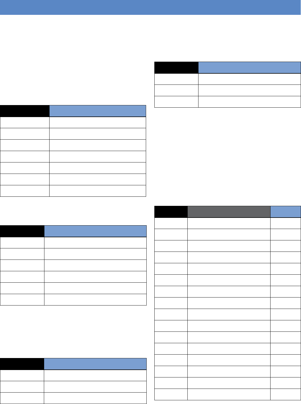
Format Subscriber Number
Surtec (8 digits)
Contact ID (4 digits)
Frontel (8 digits)
Surtec+Frontel (8 digits)
Contact ID+Frontel (4 digits)
Surtec+Video (8 digits)
Contact ID+Video (4 digits)
Phone numbers can be up to 11 digits. IP address’s are 12 digits
and are lled in for your convenience.
Phone/IP No. Number
Phone No. 1
Phone No. 2
Frontel No. 1
Frontel No. 2
Frontel IP 1 010.000.000.016
Frontel IP 2 010.000.000.031
Voice Transmitter
The system can report alarms by digital voice, via the tele-
phone line. Up to three phone numbers can be programmed.
Each number can be up to 11 digits.
Voice Trans. Phone Number
1
2
3
Email Alarm Messages
The system can send alarm messages and video les to 2
designated email address’s.
Email Address
1
2
SMTP
Access Codes
The system can handle up to 20 access codes that can be
4- to 6-digits. Each code must be named and assigned to one
of four system levels (described below), that determines the
operating limits of the assigned code.
• Level 1—arm, disarm.
• Level 2—arm, disarm, general menus.
• Level 3—arm, disarm, general menus.
• Level 4—general and conguration/programming menus.
Code No Code Name Level
Videofied Security System Installation Manual
4
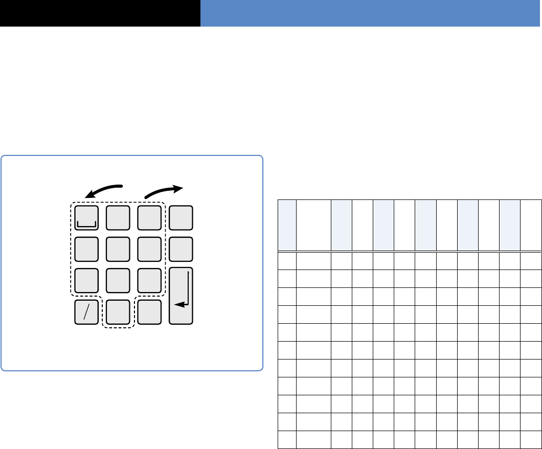
Alphanumeric Keypad Programming
Functions
On-site programming is done using a programmed alpha-
numeric keypad. The keypad functions a specic way when
performing system programming. The following diagram
describes these functions.
2
ABC 3
DEF
1
4
GHI 5
JKL 6
MNO
7
PQRS 8
TUV 9
WXYZ
0@
M
mYES
ESC
NO
CLR
Notes About Programming Functions
Timing—there is a slight delay after pressing a button
before the display responds. The more you program,
the better you’ll get with the timing.
1 - 9, 0—the number of presses of each button
determines the character displayed. When you see the
desired character on the display, pause slightly before
proceeding. The following table shows the characters
that appear with each button press.
Button
1st press
2nd press
3rd press
4th press
5th press
6th press
7th press
8th press
9th press
10th press
11th press
1 space . , ? ! ; : 1
2 A B C 2
3 D E F 3
4 G H I 4
5 J K L 5
6 M N O 6
7 P Q R S 7
8 T U V 8
9 W X Y Z 9
0 - + = / ¥ _ < > ( ) 0
@ @ $ % & * #
Left/Right Arrow Buttons—some system parameters have
preset values to choose from (Time, Date, Entry/Exit Delays,
etc.). Use these buttons to cycle through the available choices.
CLR—press and release to erase one character at a time or
press and hold to erase a complete line.
ESC/NO— pressing this button when making numerical/ text
entries returns you to the previous menu. Pressing this button
when prompted to proceed with a specic task skips to the
next menu.
Display—if there is no keypad activity for 40 seconds,
the display goes out to conserve battery power. Pressing
any button (except the red panic button) restores the display
to the same menu or entry eld before it went out.
Data Entry—menu displays that appear with a colon (:)
indicate when you can enter or select the data or setting.
For example, when INSTALLER CODE: is displayed you may
enter the desired code.
Installation Planning
Left Arrow—move backward
through menus/choices.
Right Arrow— move forward
through menus/choices.
1 - 9, 0—
use for
numerical
and text/
punctuation
entries.
M/m—
change
between
uppercase
and lowercase
characters for
text entries.
CLR—clear
numerical/
text entries.
ESC/NO—
backout of
a menu or
skip to the
next one.
YES—
proceed with
the prompted
action or accept
the displayed
entry/setting.
@—use for special text and
punctuation entries.
Keypad Programming
5
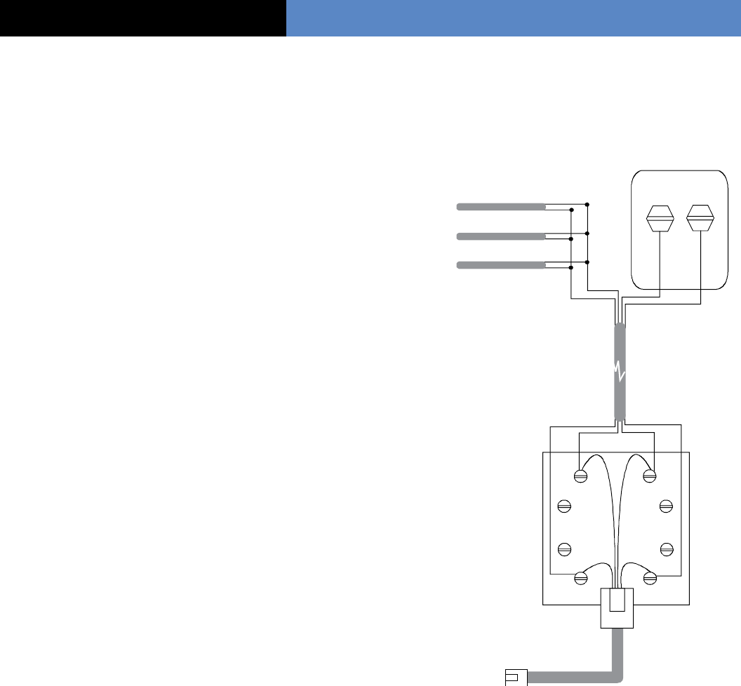
RJ31X Jack
DB-6 Cord
To control panel
phone jack.
Red Green
Gray Brown
Cable run
by installer.
Tip (+) Ring (-)
Green Red
Red
Red
Red
Green
Green
Green
Black
White
(or Yellow)
Black
White
(or Yellow)
Red Green
Lines from
phone jacks
on premises.
TELCO Block
Installation Guidelines
It is recommended that you install new systems in
the following order:
>
Run the required system wiring (phone line
for RJ31X jack).
>
Mount the control panel.
>
Power up control panel and clear memory.
>
Program alphanumeric keypad into the
control panel.
>
Program system parameters.
>
Program detectors into the control panel
and test them.
>
Mount detectors.
>
Exit programming mode.
Note: Detector programming and testing are done in one
step. When a device is programmed into the control panel,
the alphanumeric keypad displays a message automatically
prompting you to test the device.
When installing this security system, it is recommended
that you rst run the phone line for the RJ31X jack to the con-
trol panel location. This is the only wiring requirement
for this system.
Running The Required
System Wiring
The only system wiring requirement is for a phone line
connection. This line should be run before any power up or
programming procedures.
Installing an RJ31X Jack
Systems set up for central station monitoring, Email, and/or
voice messaging require that the control panel be connected
to the phone line.
It is especially important that monitored systems be
connected to the phone line with full line seizure using an
RJ31X jack. This type of connection places the control panel
ahead of all other devices connected to the phone line. This
ensures that the control panel has the priority to seize the
phone line and cut off all other phone devices in the event
of an alarm, even if the line is in use.
2. STOP. Do not connect the DB-6 plug to the control panel
phone jack at this time. You will be instructed to do this only
after all programming is completed and successful.
Phone Line ConnectionsInstallation Planning
1. Install the RJ31X jack for full line seizure as described in
the following diagram.
Videofied Security System Installation Manual
Power Up Control Panel
and Clear Memory
For new installations, always clear the control panel memory
after powering it up for the rst time, and before program-
ming any devices or other system information.
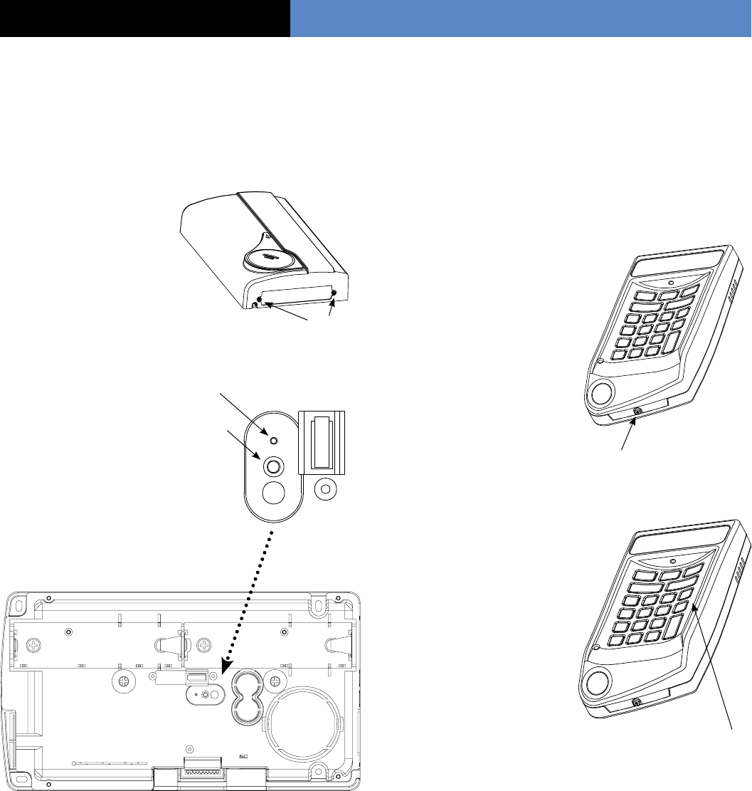
1. Remove the end
screws on the control
panel to remove its
cover and install the
batteries. The LED ashes
once after the second
battery is installed.
Note: The control panel cover
must remain off for programming.
2. Mount the control panel
at its intended location using
the four mounting holes.
3. Clear control panel
memory by using a paper
clip end. Press and hold
the program button and
wait for the LED to
ash twice, then
release the button.
Programming an Alphanumeric
Keypad into the Control Panel
An alphanumeric keypad must be programmed into the control
panel rst, in order to perform any on-site programming.
Note: The control panel assigns alphanumeric keypads to
Area 1 (Entry/Exit Delay) automatically and does not prompt
you to assign it manually.
1. Install batteries into keypad
by removing the bottom screw
and separating the base
and keypad.
2. Re-attach base with screw.
Note After installing keypad
batteries, the keypad LED
remains on if the wall tamper
is not pushed in (closed).
The tamper state does not
affect programming.
3. Put the control panel into
program mode by pressing
and releasing the program button once using a paper clip
end. The LED ashes once.
4. On the alphanumeric key-
pad, press and hold the CLR
and ESC/NO buttons together
for one second, then release
them.
Wait for the keypad display
to show KEYBOARD 1 RE-
CORDED.
5. Press YES. The display
shows RADIO RANGE TEST?
6. Press YES. The display shows
REQUEST IS BEING SENT,then TEST IN PROGRESS.
The keypad LED starts ashing once every second.
7. Take the keypad to its intended mounting location and
make sure the LED ashes continuously, indicating good
communication with the control panel.
8. Press Yes to end the radio range test, then press ESC/NO.
The display shows the following messages: ENTER THE
INSTALLER CODE 4 TO 6 DIGITS THEN YES. The display
shows CONFIRM CODE. Re-enter the installer code and press
yes.
Screw
CLR and ESC/NO Buttons
6
Installation Sequence
Screw
INIT Button
LED
(8 seconds)
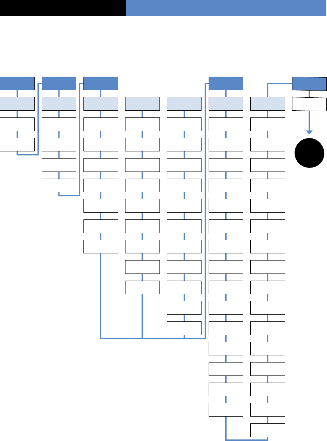
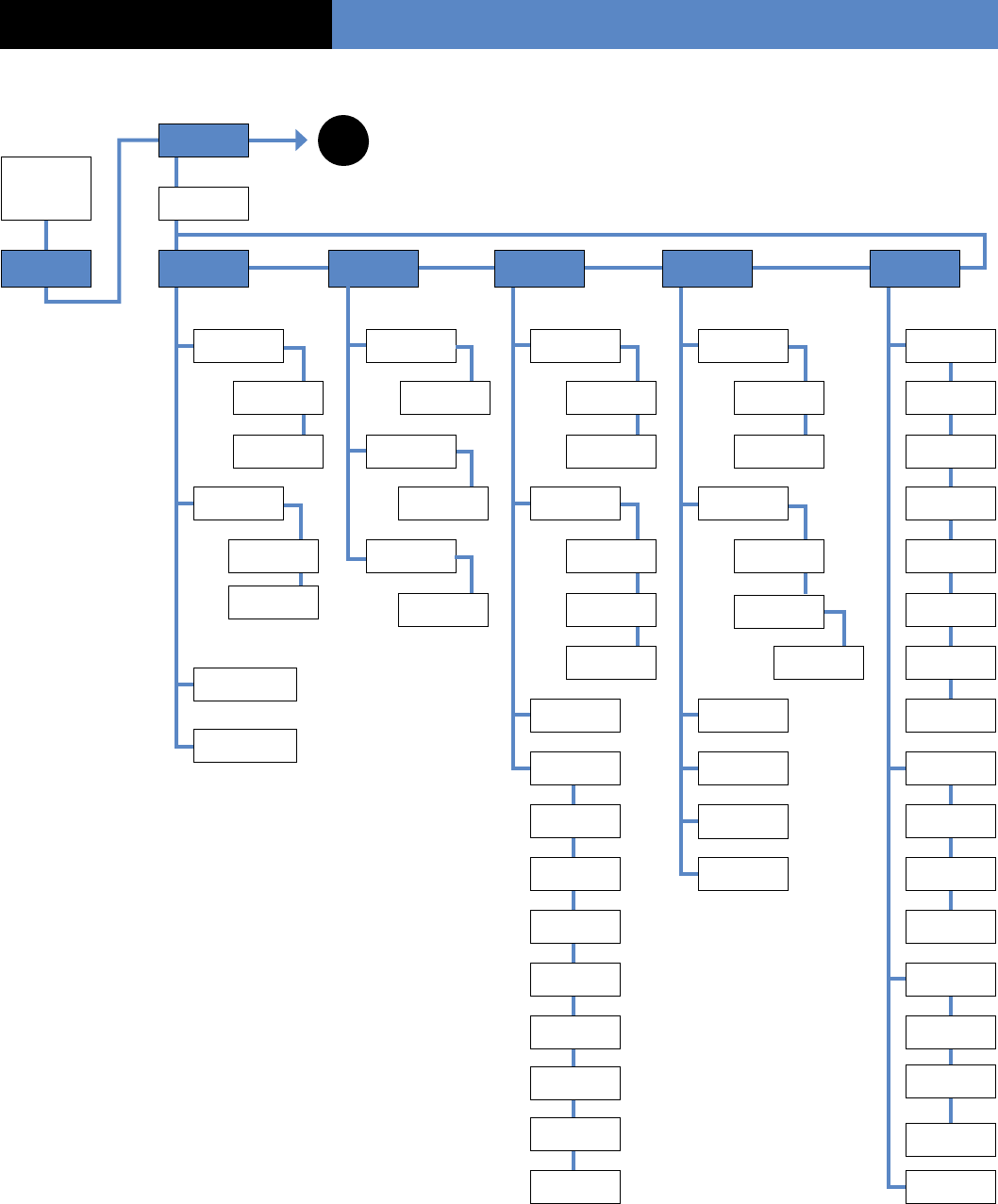
Initial Configuration Menus
The next two pages show the order in which menus appear for the initial programming session
(beginning with the Installer Code). After these pages, the manual continues with details of each
menu and the data entries required.
7
Installer
Code Date & Time Format Code/State
Modication Bypass
Activation
4 -6 Digits Year Surtec/CID Frontel Combined
Formats
Trans. State
Modications
System Code
Modications YES or No
Conrm Code Month Account
NB Phone Prex Phone Prex Detector
Alarm
Alert
(Alarm)
Code Name Day Account
NB
Account
NB
Subscriber
NB
Alert
(Alarm)
Initialization
(Alarm)
Hour Phone NBR 1 Fontel NBR 1 Phone NBR 1 Initialization
(No Trans)
Battery Fault
(302)
Minutes Phone NBR 2 Fontel NBR 2 Phone NBR 2
Panel Batteries
(No Trans)
Battery
Restore (302)
Periodic Test Frontel IP 1 Frontel NBR 1 AC Power
(No Trans)
AC Power
(301)
Test Hour Frontel IP 2 Frontel NBR 2 Phone Line
Fault (No Trans)
Phone Line
Fault (3010
Test Minutes Periodic Test Frontel IP 1 Tamper
(Alarm/End) Tamper (383)
Test Hour Frontel IP 2 Device Battery
(No Trans)
Device Battery
(301)
Test Minutes Periodic Test
Radio Jamming
(No Trans)
Radio Jamming
(344)
Test Hour Supervision
(No Trans)
Supervision
(355)
Test Minutes Periodic Test
(Alarm)
Periodic Test
(602)
No Codes
(No Trans)
Wrong Code
(461)
Duress Code
(No Trans)
Duress Code
(121)
Alarm Memory
(No Trans)
Alarm Memory
(624)
Arm/Disarm
(No Trans) Arming (400)
Disarming
(400)
Installation Sequence
SEE
NEXT
PAGE
Videofied Security System Installation Manual
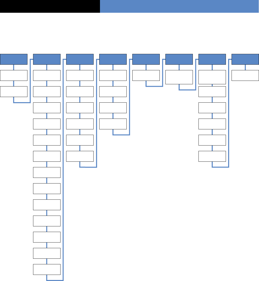
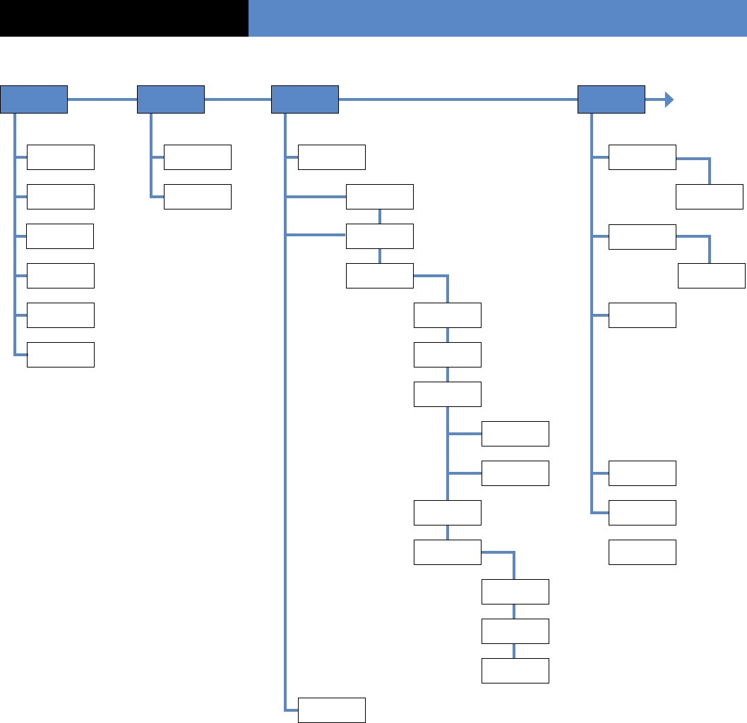
Initial Configuration Menus – continued
Completing Initial Configuration/Programming
8
Installation Sequence
Enter Your
I.D.
Sending Alarm
By Email
Voice
Transmitter Entry/Delay End of
Conguration
Panel Phone
Number
Indentication
Code
Voice Notif.
NBR 1 Area Name 1 (45 sec),
1 min 2 min
(15 sec), 30
sec, 45 sec, 1
min, 2 min
Press Init.
Button on
Device
Close the
Panel
Name or
Address Password Contact
Name Area Name 2 Radio Range
Text
Provider NB Voice Notif.
NBR 2 Area Name 3 Area
Allocation
Primary DNS Contact
Name Area Name 4 *Protect Exter-
nal Access
Secondary
DNS
Voice Notif.
NBR 3
Name
/Location
Contact
Name
SMTP Server
Internet I.D.
Internet
Password
Email Sender
Email
Address 1
Internet
Name
Email
Address 2
Internet
Name
Areas
Conguration Exit Delay Recording
Devices
Functional
Test
* Used only for Door/Window Senors, to
identify external openings, for perimeter
arming only.

9
Installer Code
Lets you program a code that is used for all programming
and maintenance functions. The installer code cannot
arm/disarm the system.
Note: An installer code must be programmed in order
to program user access codes.
1. With the display showing INSTALLER CODE: enter
the desired code, then press YES. The display shows
CONFIRM CODE.
2. Re-enter the code and press YES. The display shows
CODE NAME.
3. Enter a name for the installer code using the
alphanumeric buttons (up to 16 characters), then
press YES. The display shows “Install Entry Complete”.
Adjusting Time and Date
Initial Configuration/Programming
Installation Sequence
Data and Time
1. With the display showing DATE (Year):, press the left
or right arrow button repeatedly until the correct year
number is displayed, then press YES.
2. With the display showing DATE (Month):, press the
left or right arrow button repeatedly until the correct
month number is displayed, then press YES.
3. With the display showing DATE (Day):, press the left
or right arrow button repeatedly until the correct day
number is displayed, then press YES.
4. With the display showing DATE (Hour):, press the left
or right arrow button repeatedly until the correct hour
number is displayed, then press YES.
5. With the display showing DATE (Minutes):, press the
left or right arrow button repeatedly until the correct
minutes number is displayed, then press YES. The
display shows the programmed time and date
RECORDED. Then display shows “Entry Complete”.
Format
Lets you set up the system for reporting to a central moni-
toring station. The format selection determines how much
information must be programmed.
For Surtec and Contact ID formats:
1. With the display showing FORMAT: press either arrow
button until SURTEC or CONTACT ID is displayed, then
press
YES.
2. With the display showing PHONE PREFIX: enter the
required prex (such as a 9 with a pause for outside
line access) +
YES
or press
ESC/NO
if no prex
is required.
Note: To program a pause, press the @ button six times
for the # sign. Each # entry adds a 2-second pause.
3. With the display showing Account Number: enter
the subscriber (account) number (8 digits for Surtec,
4 digits for Contact ID), then press
YES.
4. With the display showing PHONE NBR 1: enter the
primary central station phone number the control
panel will dial rst to send reports, then press
YES.
5. With the display showing PHONE NBR 2: press
ESC/NO
to skip to the next step, or enter the secondary
phone number the control panel will dial to send
reports if attempts using the primary number are
unsuccessful, then press
YES.
6. With the display showing PERIODIC TEST:
24 HOURS, press either arrow button to select
the desired interval (1 hour, 12 hours, 24 hours,
48 hours, 7 days, or No Test) the control panel reports
a phone communication test to the central monitoring
station, then press
YES.
Note: If you select No Test and press YES, the next
menu prompt (CODE/STATE MODIFICATION?) appears.
7. With the display showing TEST HOUR: press
YES
to accept the default hour displayed, or press either
arrow button until the desired hour is displayed,
then press
YES.
8. With the display showing TEST (MINUTES): press
YES
to accept the default minutes displayed, or press either
arrow button until the desired minute is displayed, then
press
YES.
Videofied Security System Installation Manual
Connected To Monitor Station?
[YES = continue, ESC/NO = skip]

10
For Frontel Format
1. With the display showing FORMAT:, press either arrow
button until FRONTEL is displayed, then press YES.
2. With the display showing PHONE PREFIX:, enter the
required prex (such as a 9 with a pause for outside
line access) + YES or press ESC/NO if no prex is
required.
Note: To program a pause, press the @ button six times
for the # sign. Each # entry adds a 2-second pause.
3. With the display showing SUBSCRIBER NB: enter the
subscriber (account) number, (up to 16 digits), then
press YES.
4. With the display showing FRONTEL NBR 1:, enter the
primary phone number the control panel will dial rst
to send reports to Frontel Automation Software
supported central stations, then press YES.
5. With the display showing FRONTEL NBR 2:, press
ESC/NO to skip to the next step, or enter the secondary
phone number the control panel will dial to send
reports if attempts using the primary number are
unsuccessful, then press YES.
6. With the display showing FRONTEL IP 1:, enter the
primary IP number 010.000.000.016, then press YES.
7. With the display showing FRONTEL IP 2:, enter the
secondary IP number 010.000.000.031, then press YES.
8. With the display showing PERIODIC TEST: 24 HOURS,
press either arrow button to select the desired interval
(1 hour, 12 hours, 24 hours, 48 hours, 7 days, or No Test)
the control panel reports a phone communication test
to the central monitoring station, then press YES.
Note: If you select No Test and press YES, the next
menu prompt (CODE/STATE MODIFICATION?) appears.
9. With the display showing TEST HOUR: press YES to
accept the default hour displayed, or press either arrow
button until the desired hour is displayed, then press YES.
10. With the display showing TEST (MINUTES): press YES
to accept the default minutes displayed, or press either
arrow button until the desired minute is displayed,
then press YES.
For Combined Format
Surtec+Frontel, Contact ID+Frontel,
Surtec+Video, Contact ID+Video:
1. With the display showing FORMAT:, press either
arrow button until the desired combination format is
displayed, then press YES.
2. With the display showing PHONE PREFIX:, enter the
required prex (such as a 9 with a pause for outside line
access) + YES or press ESC/NO if no prex is required.
Note: To program a pause, press the @ button six times
for the # sign. Each # entry adds a 2-second pause.
3. With the display showing SUBSCRIBER NB: enter the
subscriber (account) number, (8 digits for Surtec for
mats, 4 digits for Contact ID formats), then press YES.
4. With the display showing PHONE NBR 1: enter the
primary central station phone number the control
panel will dial rst to send reports, then press YES.
5. With the display showing PHONE NBR 2: press ESC/NO
to skip to the next step, or enter the secondary phone
number the control panel will dial to send reports if
attempts using the primary number are unsuccessful,
then press YES.
6. With the display showing FRONTEL NBR 1: enter the
primary phone number the control panel will dial rst
to send reports to Frontel Automation Software
supported central stations, then press YES.
7. With the display showing FRONTEL NBR 2: press
ESC/NO to skip to the next step, or enter the secondary
phone number the control panel will dial to send reports
if attempts using the primary number are unsuccessful,
then press YES.
8. With the display showing FRONTEL IP 1: enter the primary
IP number 010.000.000.016, then press YES.
9. With the display showing FRONTEL IP 2: enter the
secondary IP number 010.000.000.031, then press YES.
10. With the display showing PERIODIC TEST: 24 HOURS,
press either arrow button to select the desired interval
(1 hour, 12 hours, 24 hours, 48 hours, 7 days, or No
Test) the control panel reports a phone communication
test to the central monitoring station, then press YES.
Note: If you select No Test and press YES, the next
menu prompt (CODE/STATE MODIFICATION?) appears.
11. With the display showing TEST HOUR: press YES to
accept the default hour displayed, or press either arrow
button until the desired hour is displayed, then press YES.
12. With the display showing TEST (MINUTES): press YES
to accept the default minutes displayed, or press either
arrow button until the desired minute is displayed,
then press YES.
Initial Configuration/Programming
Installation Sequence

11
Code/State Modification?
[YES = continue, ESC/NO = skip]
Tran. State Modification
Lets you change the control panel default settings for
how and/or whether certain conditions are reported to
the central station. There are three possible settings
for each state:
Alarm—alarm reports only
Alarm/End—alarm and restore reports
No Trans—no report
There are 15 states described below
with their default setting that can be changed.
>
DEVICE—Alarm
>
ALERT —Alarm
>
INITIALIZATION —No Trans
>
PANEL BATTERIES—No Trans
>
AC POWER—No Trans
>
PHONE LINE FAULT—No Trans
>
TAMPER—Alarm/End
>
DEVICE BATT.—No Trans
>
RADIO JAMMING—No Trans
>
SUPERVISION—No Trans
>
PERIODIC TEST—Alarm
>
WRONG CODES—No Trans
>
DURESS CODE—No Trans
>
ALARM MEMORY—No Trans
>
ARM/DISARM—No Trans
1. With the display showing TRANS. STATE MODIFICATION:
press Yes. The display shows the rst state/setting
DETECTOR ALARM.
2. Press YES to change this setting or press either arrow
button until the desired state/setting is displayed, then
press YES. A colon (:) appears indicating that you may
now change the current setting.
3. Press either arrow button until the desired setting
appears, then press YES. The colon disappears and the
the new setting is displayed.
4. Repeat steps 2 and 3 for all other setting changes.
5. When all desired changes are done, press ESC/NO.
The display returns to TRANS. STATE MODIFICATION.
6. Press the right arrow button once. The display shows
ALARM CODE MODIFICATION.
Alarm Code Modification
Lets you change the default alarm reporting code of
each system device.
Note: Although this menu appears at this point in the
cycle, pressing YES produces the display message NO
EQUIPMENTS RECORDED. After devices (equipment)
and all initial system programming are programmed
(recorded) into control panel memory, you must start
a new programming session to modify these codes.
System Code Modification
Lets you change the system codes the control panel
reports to the central station. There are 16 codes
described below with their default settings that can
be changed.
>
ALERT—code 120
>
INITIALIZATION—code 305
>
BATTERY FAULT—code 302
>
BATTERY RESTORE—code 302
>
AC POWER—code 301
>
PHONE LINE FAULT—code 351
>
TAMPER—code 383
>
DEVICE BATTERY—code 384
>
RADIO JAMMING—code 344
>
SUPERVISION—code 355
>
PERIODIC TEST—code 602
>
WRONG CODES—code 461
>
DURESS CODE—code 121
>
ALARM MEMORY—code 624
>
ARMING—code 400
>
DISARMING—code 400
1. With the display showing ALARM CODE MODIFICATION,
press the right arrow button once. The display shows
SYSTEM CODE MODIFICATION.
2. Press YES. The display shows ALERT CODE 120
3. Press either arrow button until the desired system
code is displayed, then press YES. A colon (:) appears
indicating that you may now change the current setting.
4. Enter the desired 3-digit code, then press YES.
The colon disappears and the new setting is displayed.
5. Repeat steps 3 and 4 for all other setting changes.
6. When all desired changes are done, press ESC/NO.
The display returns to SYSTEM CODE MODIFICATION.
Initial Configuration/Programming
Installation Sequence
Videofied Security System Installation Manual

12
Enter Your I.D.
Your Phone Number
1. With the display showing PANEL PHONE NUMB:, enter
the customer site phone number, then press YES. The
display shows NAME OR ADDRESS.
2. Enter the customer name and address, then press YES.
The display shows “Name and Address Complete”.
Sending Alarm By Email
Lets you enter an Email address so the customer can
receive alarm notications by the Internet.
Note: Pressing ESC/NO displays the message EMAIL
ALARM DISABLED and skips to the next menu.
1. With this menu displayed, press YES to program an
Email address. The display shows: INTERNET ACCESS
PARAMETERS, then IDENTIFICA. CODE.
2. Enter a customer identication code (up to 15 charac
ters), then press YES. The display shows PASSWORD:.
3. Enter the customer password, then press YES.
The display shows: PROVIDER NO:.
4. Enter the customer’s Internet provider phone number,
then press YES. The display shows PRIMARY DNS:.
5. Enter the rst DNS (IP address), then press YES.
The display shows SECONDARY DNS.
6. Enter the second DNS (IP address), then press YES.
The display shows SMTP SERVER:.
7. Enter the SMTP server address (up to 15 characters),
then press YES. The display shows INTERNET I.D.:.
8. Enter the Internet (Email) ID address, then press YES.
The display shows INTERNET PASS:.
9. Enter the Email password, then press YES. The display
shows EMAIL SENDER:.
10. Enter the sender’s Email address, then press YES.
The display shows EMAIL ADDRESS 1.
11. Enter the rst recipient’s Email address, then press
YES. The display shows INTERNET NAME:.
12. Enter the recipient’s internet name, then press YES.
The display shows EMAIL ADDRESS 1 RECORDED!, then
EMAIL ADDRESS 2.
13. Enter the second recipient’s Email address, then press
YES. The display shows INTERNET NAME:
14. Enter the recipient’s internet name, then press YES.
The display shows EMAIL ADDRESS 2 RECORDED!
Bypass Activiation
Lets you set up the system so operators in Frontel
supported central stations can initiate contact with
and access the system.
1. With the display showing BYPASS ACTIVATION?, press
YES or ESC/NO.
Initial Configuration/Programming
Installation Sequence

13
Area Configuration
Using The Voice Transmitter
Lets you set up the system for voice reporting to as
many as three customer designated phone numbers.
The report includes the device, zone, alarm type, time,
and date.
During an alarm, the control panel makes three
attempts using the rst phone number. If all attempts
are unsuccessful, the control panel waits for one minute
and makes three more attempts using the second
phone number. If these attempts are unsuccessful, the
control panel waits for one minute and makes three
more attempts using the third phone number.
Follow these steps to enter the destination phone
numbers, contact /recipient names, passwords, and
name assigned to each password.
Note: Pressing ESC/NO displays the message VOICE
TRANS. DISABLED and skips to the next menu.
1. With this menu displayed, press YES to set up the voice
transmitter. The display shows VOICENOTIF . PHONE
NBR 1:.
2. Enter the rst phone number destination, then press
YES. The display shows CONTACT NAME.
3. Enter the appropriate contact name, then press YES.
The display shows “Entry Complete”, then
VOICENOTIF . PHONE NBR 2:.
Note: If only programming one voice transmitter number,
press ESC/ NO to skip programming the next two voice
transmitter numbers.
4. Enter the second phone number destination, then press
YES. The display shows CONTACT NAME:.
5. Enter the second appropriate contact name, then
press YES. The display shows “Entry Complete”, then
VOICENOTIF . PHONE NBR 3:.
Note: If only programming two voice transmitter
numbers, press ESC/NO to skip programming the third
voice transmitter number.
6. Enter the third phone number destination, then press
YES. The display shows CONTACT NAME:.
7. Enter the third appropriate contact name, then press
YES. The display shows “Entry Complete”.
Area Name 1
Lets you name each of the four areas used for
identifying the different areas of the installation.
Area 1 is predened from the factory for alphanumeric
keypads and any entry/exit delay points. Area 1 should
be named appropriately to identify it as the delay area.
Areas 2, 3, and 4 have no predened default
properties and can be named as required for the
installation. For example,
Area 2 could be congured and named as Main Level,
Area 3 Upper Level, and Area 4 Basement.
1. With the display showing AREA NAME 1: enter the
desired name, then press YES. The display shows
[NAME], AREA 1 RECORDED, then AREA NAME 2.
2. Enter the desired area 2 name, then press YES.
The display shows [NAME], AREA 2 RECORDED,
then AREA NAME 3.
3. Enter the desired area 3 name, then press YES. The
display shows [NAME], AREA 3 RECORDED, then AREA
NAME 4.
4. Enter the desired area 4 name, then press YES. The
display shows [NAME], AREA 4 RECORDED.
Exit Delay
Determines the amount of time users have to leave
through a delay door without causing an alarm.
Note: For UL Listed installations, the Exit Delay must be
set to 60 seconds or less.
>
With the display showing EXIT DELAY: 45 sec, press
YES to accept the default setting, or press either arrow
button until the desired exit delay time appears (45 sec,
1 min, or 2 min), then press Yes.
Entry Delay
Determines the amount of time users have to disarm
the system upon entry, before an alarm occurs.
Note: For UL Listed installations, the Entry Delay must
be set to 45 seconds or less.
>
With the display showing ENTRY DELAY: 15 sec, press
YES to accept the default setting, or press either arrow
button until the desired entry delay time appears (15
sec, 30 sec, 45 sec, 1 min, or 2 min), then press Yes.
Initial Configuration/Programming
Installation Sequence
Videofied Security System Installation Manual
14
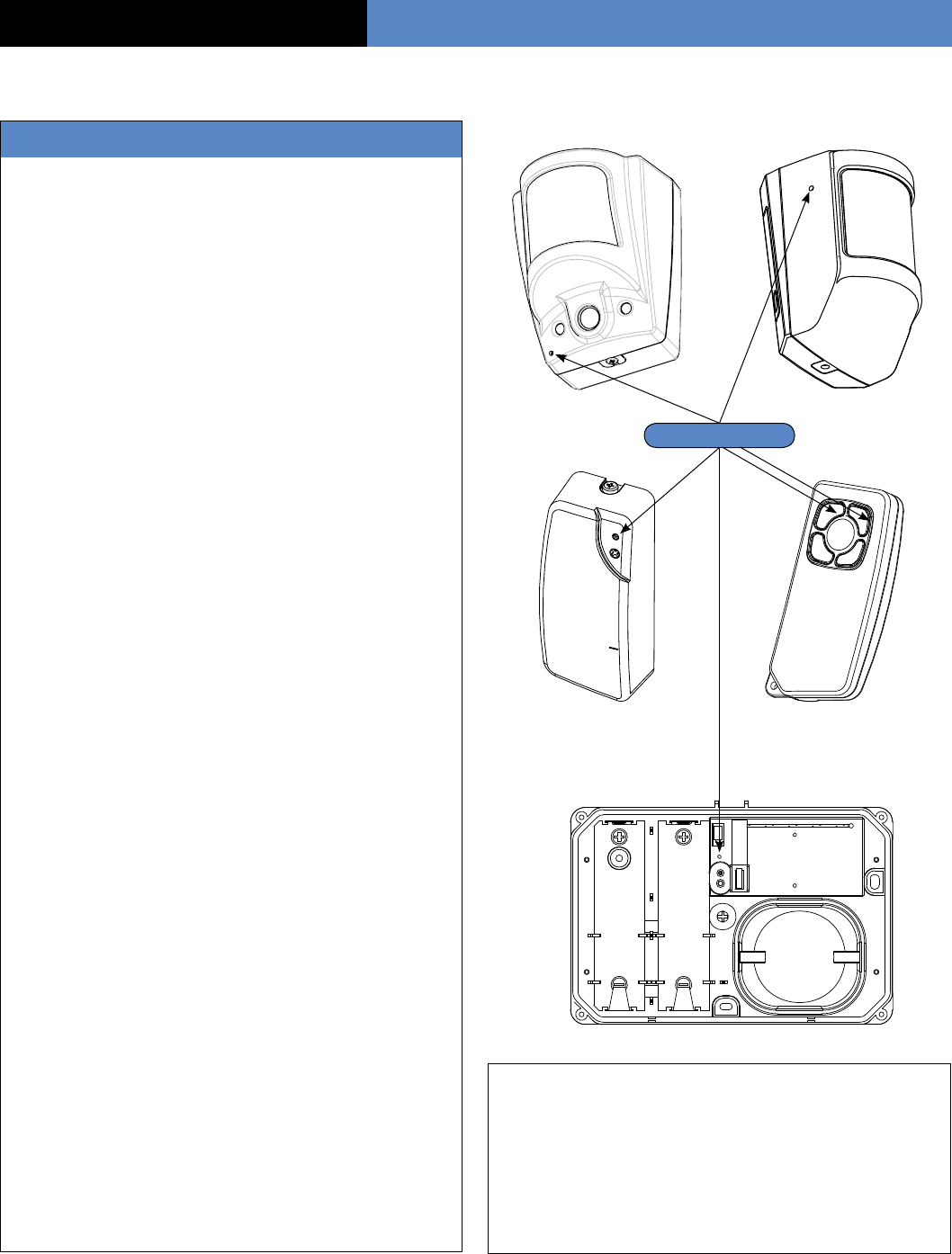
Recording Equipment
Press Init. Butt. On Equipment
Lets you program system devices into the control
panel memory.
1. Install batteries into all system devices* (refer to the
installation instructions). Make sure bases are attached
to devices to secure the tamper switches.
2. Press and release the program button on the desired
device using a paper clip end (see graphics on right side
of page for device program button locations). The
device LED starts ashing. Wait for the keypad display
to show “Device Type 1 Recorded”.
3. Press YES. The display shows RADIO RANGE TEST?
Press YES again. The device LED starts ashing and
the display shows TEST IN PROGRESS.
Note The Radio Range Test prompt does not appear
when programming keyfobs.
4. Take the device to its intended mounting location and
make sure the LED ashes once every second,
indicating good communication with the control panel.
5. Press YES to end the radio range test, then press
ESC/NO.
6. The display now shows AREA ALLOCATION: AREA:1.
Press either arrow button repeatedly until the desired
area number appears, then press YES.
Note The Area Allocation prompt does not appear
when programming keyfobs or sirens.
7. The display shows PROTECT AN EXTERNAL ACCESS?
Press YES or ESC/NO, whichever is appropriate for
this device.
Note The Protect An External Access prompt only
appears when programming door contacts.
8. The display shows NAME + LOCATION. Enter the
appropriate device name/location (up to 16 characters),
then press YES. The display shows the device number
and name for your verication.
Note The Name + Location prompt does not appear
when programming keyfobs or sirens.
9. Press YES. The display shows FUNCTIONAL TEST?
Press YES again and verify the device operation.
For example, waving your hand in front of a motion
detector should activate its LED indicating detection.
Moving a magnet away from a door contact should
activate its LED indicating detection.
10. Press YES to end functional test.
11. The display shows RECORDING NEW EQUIPMENTS?
Press YES to continue programming remaining devices.
Camera PIR Motion Detector
Door Contact Keyfob (Press and hold On
and Off buttons for 5 seconds,
then release.)
Sirens
Program Buttons
Initial Configuration/Programming
Installation Sequence
* All installation instructions, manuals are available at our web site www.videoed.com. Go to dealer support, click on “To Login”. User
name = “your rst name”, the Password = “videoed”. Then click on “Technical Documentation” you now have access to all RSI instal-
lation sheets and manuals

15
Completing Initial
Configuration/Programming
After the last device is programmed, press ESC/NO.
The display shows END OF CONFIGURATION, then
changes to CLOSE THE PANEL.
STOP!
It is important that you rst mount all devices, then
secure the cover on the control panel. Failure to follow
this order of tasks will cause a tamper condition
from devices.
1. With the display showing CLOSE THE PANEL, do not
press YES.
2. Mount all system devices at their permanent locations
3. Connect the supplied phone cord into the control panel
phone jack.
Note: The phone line can be run inside the wall
and through the back of the control panel, or it can
be run inside the wire cavity and out the end of the
control panel.
4. With the keypad display showing CLOSE THE PANEL,
secure the cover onto the control panel. The display
shows PANEL TAMPER ON OPEN = ALARM, then
OPERATION COMPLETED?
5. Press YES. The display shows SYSTEM CHECK
IN PROGRESS.
The system performs a test of all programmed
devices. If all tampers are closed and battery
conditions in all devices are good, the display shows
INSTALLATION SUCCESSFUL, then changes to the
date, time, and current status (DISARMED LVL:3).
If there is no keypad activity for 40 seconds, the
display goes out to conserve battery power.
Initial Configuration/Programming
Installation Sequence
Videofied Security System Installation Manual

16
Changing Settings After Completing
Initial Conguration/Programmin
Once the control panel cover is secured in place,
removing it causes a tamper alarm. Changing settings
made during the initial conguration or adding devices
now requires setting the system to Access Level 4,
using your installer code.
Setting the System to Level 4
1. With the display showing [DATE/ TIME], DISARMED
LEVEL:3, press the right arrow button once. The display
shows ACCESS LEVEL 3.
2. Press YES. The display now shows a colon (:) between
LEVEL and 3 (LEVEL:3).
3. Press the right arrow button once to change the
level number to 4, then press YES. The display shows
BADGE OR CODE.
4. Enter your installer code, then press YES. The display
shows ACCESS LEVEL 4.
You can now access the following menus:
>
Conguration
>
Maintenance
>
Event Log
>
Badges-Access codes
>
Programmable Features
To make changes press the arrow keys to go to the desired
menu and press YES. Only the Conguration & Badges-Ac-
cess Codes menus require an access code to enter to view
or change data. Review the system menus on the next few
pages to see the programmable options.
System Menus
The next two pages show the order in which menus
now appear with the system in operational mode.
There are six main menus available in the operating
mode. The system level determines which menus are
available, some with their own set of submenus.
The main menus and submenus are described
afterward. To access these menus, press either arrow
button until the desired main menu is displayed, then
press YES to proceed.
After Completing Initial Configuration/ProgrammingChanging Settings
17
Area
Conguration
Area
Content
SEE
NEXT
PAGE
Date/Time
Status/Level
Display
Access Level
After Completing Initial Configuration/ProgrammingChanging Settings
Conguration
Badge or Code
General
Parameter
NBR of Rings
Before Connect
By Pass
Enabled/Disabled
Phone Prex
Alarm Modes
Programmable
Fully Armed
Areas:
State:
Alarm
Special Mode 1
Alarm
Special Mode 2
Responding
Party List
Select/Modify
Phone Numbers
Enter New
Phone Number
Select/Modify
Email Address
Enter New
Email Address
Mode Name
Email Sender
Internet Access
Parameters
Identication
Code
Password
Provider Number
Primary DNS
Secondary DNS
Provider Number
Primary DNS
Secondary DNS
Areas and
Devices
Add A New
Device
Device
Conguration
Areas
Entry Delay
( 15 sec )
Exit Delay
( 45 sec )
Delay Beeps
Enabled/Disabled
Siren Panel
( By Default)
Conguration
Monitor Station
Responding Party
Phone List
Video
Alarm Address
Devices
Changing Names
Area (1 - 4 )
Intercom
Enable/Disable
Monitoring
Parameters
Monitoring
Enable/Disable
Account NBR:
Format
Phone Number 1
Phone Number 2
Fontel IP 1
Fontel IP 2
System Armed
Enable/Disable
Periodic Test
Test Period
Enable/Disable
Test Hour
Alarm Codes
Trans. State
Modication
Alarm Code
Modication
System Code
Modication
Levels 1,2,3,4
Videofied Security System Installation Manual
Phone Number
Panel Phone NBR:
Site Identication
System Armed
(1-15)
System Disarmed
(1-15)
Areas:
State:
Areas:
State:
18
Maintenance Programming MenuChanging Settings
Maintenance Events Log Badges
Access Codes
Programmable
Features
Levels 1,2,3,4 Levels 1,2,3,4 Levels 1,2,3,4 Levels 1,2,3,4
Back To
Date/Time Display
Maintenance
Replace Battery
Device Locating
Audio Test
Equipment
Display Faulty
Devices
Modify
Date/Time
Functional Test
Devices
Select
Last Events
Send Log
File By Email
External Mode
External Mode
Badge or Code
Enter
A Badge/Code
Badge/Code
Conguration
Code List
Modify Name
Badge/Code
Access Level
Schedule
Authorized
Select/Modify
Schedules
Enter A New
Schedule
Zones Disarmed
Alarm Modes
Allowed
Special Mode 1
Special Mode 2
Alarm Calls
Videomail Alarm
Panic Button
Enable/Disable
Exit Delay
( 45 sec )
Delay Beeps
( Allowed )
Siren Panel
( By Default )
Alarm
Transmission
Email Address

19
Access Level— available in Levels 1, 2, 3, and 4
This menu shows the current system level and lets you
change the level. Increasing the level always requires a valid
access code assigned to that level. Lowering the level does
not require an access code.
Configuration— available only in Level 4
This menu and the listed submenus below allow access to
review and/or change system settings entered during the
initial conguration/programming session.
>
General Parameters
Site Identication (phone number, name or address)
Number of Rings Before Connect system armed/disarmed
Bypass (enabled/disabled)
Phone Prex
>
Alarm (Arming) Modes Programmable
Alarm
Alarm Special Mode 1
Alarm Special Mode 2
>
Responding Party List
Alarm Transmission (select/modify phone numbers,
enter a new phone number)
Videomail Alarm Address (select/modify Email addresses,
enter a new Email address)
>
Email Sender
>
Internet Access Parameters
Identity. Code
Password
Provider Number
Primary DNS
Secondary DNS
SMTP Server
Internet ID.
Internet Password
Responding Party Phone List (select/modify phone
numbers, enter a new phone number)
>
Areas and Devices
Equipment (add a new device, device conguration) Areas
>
Conguration Monitor. Station
Monitoring Parameters (subscriber number, format, phone
numbers, IP address’s)
Periodic Test
Alarm Codes
Intercom (enabled/disabled)
Maintenance— available in Levels 2, 3, and 4
This menu allows access for system servicing.
>
Modifying Date/Time
>
Maintenance Replace Battery
>
Functional Test Devices
>
Device Locating (identify/locate detectors)
>
Audio Test Equipment
>
Display Faulty Devices
Events Log— available in Levels 2, 3, and 4
This menu lets you view and send via Email, a list of all
system activity and events.
Badges, Access Codes— available in
Levels 2, 3, and 4 (only with a valid Level 2, 3, or 4 access
code) This menu and the submenus listed below let you add,
modify, assign access levels to, and/or delete system access
codes. Schedules can also be created and assigned to codes
as needed.
>
Recording A Badge/Code
>
Badges/Codes Conguration
Modify Name Badge/Code
Access Level
Schedule Authorized Areas
Alarm (Arming) Modes
>
Deleting Badges/Codes
Programmable Features— available in Levels 2,
3, and 4 This menu allows access to the submenus below that
let you view and/or change the system phone and IP numbers
programmed during the initial conguration/programming
mode.You can also enable or disable the panic button.
>
Alarm Calls
>
Panic Button Enabled/Disabled
Programming Access Codes– At this
point in new installations, the only programmed access code
is the installer code. This code, and any future programmed
Level 4 codes are restricted from operating (arming/disarm-
ing) the system.
To make the system operational for the customer, access
codes assigned to Levels 1, 2, or 3 must be programmed.
Access codes can be 4 to 6 digits. The differences between
access levels are described below.
>
Level 1—arm and disarm only.
>
Level 2—arm, disarm, Maintenance, Events Log,
Badges Access Codes, and Programmable Features menus.
>
Level 3—same as Level 2.
>
Level 4—Conguration, Maintenance, Events Log, Badges
Access Codes, and Programmable Features menus.
Note: All new access codes are assigned to Level 3
by default. The procedure below includes access level
assignment for a new code (steps 9 - 11). To change the ac-
cess level assignment at a later time, refer to the next section
“Changing Access Level Assignments”.
After Completing Initial Configuration/ProgrammingChanging Settings
Videofied Security System Installation Manual

20
1. With the display showing the current date, time, and
LVL:4, press the left arrow button twice. The display
shows BADGES ACCESS CODES.
2. Press YES. The display shows BADGE OR CODE.
Enter your installer code + YES. The display shows
RECORDING A BADGE/CODE.
3. Press YES. The display shows BADGE OR CODE.
4. Enter the desired code + YES. The display shows
CONFIRM THE CODE.
5. Re-enter the code + YES. The display shows
CODE NAME:.
6. Enter the desired name + YES. The display shows
[NAME] ENTRY COMPLETE, then returns to
RECORDING A BADGE/CODE.
7. Press the right arrow button once. The display shows
BADGES/CODES CONFIGURATION.
8. Press YES. The display shows MODIF NAME
BADGE CODE.
9. Press the right arrow button once. The display shows
ACCESS LEVEL 3.
10. Press YES. The display now shows a colon (:) between
LEVEL and 3.
11. Press either arrow button until the desired level is
displayed, then press YES. The display shows the new
level assignment.
12. Press ESC/NO three times to return to BADGES
ACCESS CODES.
13. Repeat steps 2 - 12 for remaining codes.
Changing Access Level Assignments
You can change the access level assignments as needed any-
time, using the following steps.
1. With the display showing the current date, time, and
LVL: 4, press the left arrow button twice. The display
shows BADGES ACCESS CODES.
2. Press YES. The display shows BADGE OR CODE.
Enter your installer code + YES. The display shows
ENTER A BADGE/CODE.
3. Press the right arrow button once. The display shows
BADGES/CODES CONFIGURATION.
4. Press YES. The display shows the rst programmed
access code.
5. Press either arrow button until the desired code
appears, then press YES. The display shows MODIF
NAME BADGE/CODE.
6. Press the right arrow button once. The display shows
ACCESS LEVEL 3.
7. Press YES. The display now shows a colon (:) between
LEVEL and 3.
8. Press either arrow button until the desired level
assignment appears, then press YES. The display
shows the new level assignment.
9. Press ESC/NO.
10. Repeat steps 5 - 9 for other level assignment changes
Changing Access Code Alarm Mode
Restrictions– After programming a new access
code, altering alarm (arming) modes for any access code,
using the following steps.
1. With the display showing date, time and LVL 4, press
the left arrow button twice. The display shows BADGES
ACCESS CODES.
2. Press YES. The display shows BADGE OR CODE. Enter
a Level 2 or 3 access code + YES. The display shows
ENTER A BADGE/CODE.
3. Press the right arrow button once. The display shows
BADGES/CODES CONFIGURATION.
4. Press YES. The display shows the rst programmed
access code.
5. Press either arrow button until the desired code
appears, then press YES. The display shows MODIFY
NAME BADGE/CODE.
6. Press the left arrow button once. The display shows
ALARM MODES ALLOWED.
7. Press YES. The display shows SPECIAL MODE 1
ALLOWED.
8. Press either arrow button until the desired mode
appears, then press YES. The display shows a colon (:)
next to ALLOWED.
9. Press either arrow button once. The display changes
to DISABLED.
10. Press YES. The display shows the new alarm (arming)
mode setting without the colon.
11. Repeat steps 5 - 10 for other code restriction changes.
Deleting Access Codes– Delete access codes as
needed anytime, using the following steps.
1. With the display showing the current date, time, and
LVL: 4, press the left arrow button twice. The display
shows BADGES ACCESS CODES.
2. Press YES. The display shows BADGE OR CODE.
Enter your installer code + YES. The display shows
ENTER A BADGE/CODE.
3. Press the left arrow button once. The display shows
DELETING BADGES/CODES.
4. Press YES. The display shows the rst programmed
access code.
5. Press either arrow button until the desired code
appears, then press YES. The display shows
DELETING CODE.
6. Press YES again. The display shows CODE DELETED.
7. Repeat steps 5 - 6 to continue deleting codes.
After Completing Initial Configuration/ProgrammingChanging Settings

21
Creating Schedules
Schedules determine when a specic access code can be used
to arm and disarm the system. A schedule consists of a day,
beginning time, and ending time that the specic access code
can be used. Up to ve schedules can be programmed for
each access code.
Make copies of the table at right to ll in the necessary sched-
ule information for each code. Enter this information using the
procedure below.
1. With the display showing the current date, time, and
LVL: 4, press the left arrow button twice. The display
shows BADGES ACCESS CODES.
2. Press YES. The display shows BADGE OR CODE.
Enter your installer code + YES. The display shows
ENTER A BADGE/CODE.
3. Press the right arrow button once. The display shows
BADGES/CODES CONFIGURATION.
4. Press YES. The display shows the rst access code.
5. Press the left or right arrow button until the desired
code is displayed, then press YES. The display shows
MODIF NAME BADGE/CODE.
6. Press the right arrow button twice. The display shows
SCHEDULE AUTHORIZED.
7. Press YES. The display shows SELECT/MODIFY
SCHEDULES.
8. Press the right arrow button once. The display shows
ENTER A NEW SCHEDULE.
9. Press YES. The display shows BEGIN SCHEDULE 1 Mon.
10. Press either arrow button until the desired weekday
appears, then press YES. The display shows BEGIN
SCHEDUL 1 Day= 00:00.
11. Press either arrow button until the desired hour
appears, then press YES. The display does not change.
12. Press either arrow button until the desired minutes
appear, then press YES. The display shows END
SCHEDULE 1 Day.
13. Press YES. The display shows END SCHEDULE
1 Day= 00:00.
14. Press either arrow button until the desired hour
appears, then press YES.
15. Press either arrow button until the desired minutes
appear, then press YES. The display shows SCHEDULE
ENTERED, then returns to ENTER A NEW SCHEDULE.
Code
#
Sched.
#
Day
Start Time End Time
1
2
3
4
5
1
2
3
4
5
1
2
3
4
5
1
2
3
4
5
1
2
3
4
5
1
2
3
4
5
1
2
3
4
5
1
2
3
4
5
After Completing Initial Configuration/ProgrammingChanging Settings
Videofied Security System Installation Manual

22
Setting Up Special Arming Modes 1 and 2
These undened special arming modes are used for Special
Area arming of your system. You can set up which Areas of
your premises are armed in mode 1 & 2 and if an alarm would
be silent or audible. An ofce in the home could be armed/
disarmed independently.
Program Special Arming Modes 1 and 2
1. Set the system to CONFIGURATION using the
installer code.
2. Press the right arrow until ALARM MODE
PROGRAMMABLE is displayed.
3. Press YES. The display shows ALARM.
4. Press right arrow, display shows ALARM SPECIAL MODE 1.
5. Press YES. The active areas for that special Armand
mode are displayed.
AREAS: 1234 are active in Special Arming Mode 1.
STATE: ABAA are the state of that Area when the special
arming level 1 is used, Areas 1,3 and 4 are armed, Area 2 is
disarmed. If Area 2 is your ofce, it is not armed when
Areas 1, 3 and 4 are using Special Arming Mode 1.
There are four possible arming states you can select for
each Area that is active in Special arming level 1 or 2,
they are:
A = Area totally armed
B = Area totally disarmed
C = Only entry sensors are armed
D = Only entry sensors on perimeter openings are armed
Press the Area number 1-4 and select A-D for the Area,
Press Yes, you will then be prompted for the special
arming mode siren options: ALARM SIREN, SIGNAL DE
LAY BEEPS, ALARM SILENT, ALARM WITHOUT SIREN
Press the right arrow button until the display shows the
siren mode you want, press Yes. The display now shows:
DESIGNATION MODE SPECIAL MODE 1 you can hit ESC/
NO and back out of conguration or rename special
arming mode 1 to a new home of your choice. To do this:
Press Yes, the display shows OPERATING MODE_now
input your new name and press the Yes key.
When nished, press and hold the ESC/NO key until you
get back to the Date and time idle text.
Put the alarm panel back into level 2 or 3 when all
conguration/programming is complete.
Viewing the History/Event Log
Events are any system activity such as arming, disarming,
alarms, access codes entered, and system programming
changes. The control panel uses built-in memory to record
each system event. This log cannot be cleared or erased and
accumulates events for up to a full year. As additional events
occur, the control panel automatically deletes the oldest
event. This ensures an accurate history.
You can view the contents of the history/event log using
a system Keypad or by instructing the system to send the
complete event log as an Email.
Viewing by Keypad
This method lets you view the most recent events.
1. Set the system to Level 2 or 3.
2. Press either arrow button until the display shows
EVENT LOG.
3. Press Yes. The display shows SELECT LAST EVENTS.
4. Press Yes. The last or most recent event is displayed.
5. Press the left arrow button to view previous events.
6. When nished, simply stop pressing buttons. The dis
play returns to the date/time and current status, then
goes blank to conserve battery power.
Sending History/Log File by Email
This method lets you send a complete history/log le to a
desired Email address for viewing. The Email includes an
attachment (in ASCII le format) that can be opened using a
word/text processor such as Microsoft® Word® or Notepad®
1. Set the system to Level 2 or 3.
2. Press either arrow button until the display shows
EVENT LOG.
3. Press Yes. The display shows SELECT LAST EVENTS.
4. Press the right arrow button once. The display shows
SEND LOG FILE BY EMAIL.
5. Press Yes. The display prompts you to identify the
Email address.
6. Enter the desired Email address using the alphanumeric
Keypad buttons, then press Yes. The display shows
DELIVER?
7. Press Yes. The display indicates when delivery is
completed.
Note: If the display message indicates the Email was
undeliverable, check the Email address to make sure it
is valid/correct and try again.
After Completing Initial Configuration/ProgrammingChanging Settings

23
Electrical Data
Power requirements: Four 3.6 V batteries
Battery type: Lithium, LSH20
Battery life (estimated): At least 4 years
RF technology: S2VIEW®
Radio type: Bidirectional
Operating frequency: 915 MHz 25 channel spread spectrum
Frequency allocation: Automatic by control panel
Transmission speed: 9600 bps
Transmission security: AES algorithm encryption
Radio jam detection: Yes
Supervision: Every 8 minutes
Antenna: Integrated
Tamper detection: Cover removal or removal from mounting surface
Siren output: 110 dba @ 1 meter
Siren duration: 3 minutes maximum
Programming:
Alphanumeric Keypads or Frontel Automation Software
Devices per system: 24 maximum
Access codes: 20 maximum
Installer codes: One (for system programming only)
Security levels: 4
Arming modes: 4
Area: 1 (Area 1 predened from factory for entry/exit delay.
Areas 2, 3, & 4 programmable)
Communicator transmitter: Embedded; digital, voice, IP
Communicator type: Analog phone line PTSN (TBR21)
Dialing: DTMF
Protocols: Frontel, CID
IP stack: IP, TCP/IP, HTTP, SMTP, PPP
Voice alarm transmission: Up to 3 phone numbers
Voice server: Pre-recorded messages
Email transmission: Up to 2 Email addresses
Remote maintenance: Frontel protocol only
Video transmission: By Frontel protocol to
central monitoring station, or by Email
Video format: MPEG V1.0 video le, 5 frames/second
Video le size: 200 Kbytes
Video framing: 5 frames/second
Picture format: JPEG
Picture size: 320 x 240 pixels
History/Event Log: 4,000 events stored in ash memory
Operating temperature: 32° - 104° F (0° - 40° C)
Maximum relative humidity: 70%, non-condensing
UL Listings: 1023 (applied for)
Physical Data
Material: ABS—ULV0
Dimensions: (LxWxD): 11 in. x 6-1/4 in. x 2-1/4 in.
(280 mm x 158 mm x 57 mm)
Weight: 34.5 oz./980 g (without batteries)
History/Event Log: 4,000 events stored in ash memory
Operating temperature: 32° - 104° F (0° - 40° C)
Maximum relative humidity: 70%, non-condensing
UL Listings: 1023 (applied for)
Specifications
Videofied Security System Installation Manual