RSIAlarm TE00 Remote Control of alarm system User Manual Product Catalog
RSIAlarm Remote Control of alarm system Product Catalog
UserManual.wiki
>
RSIAlarm
>
TE00 User Manual
User Manual
Navigation menu
Upload a User Manual
Namespaces
Wiki Guide
HTML
PDF
Info
Views
User Manual
Discussion / Help
Navigation
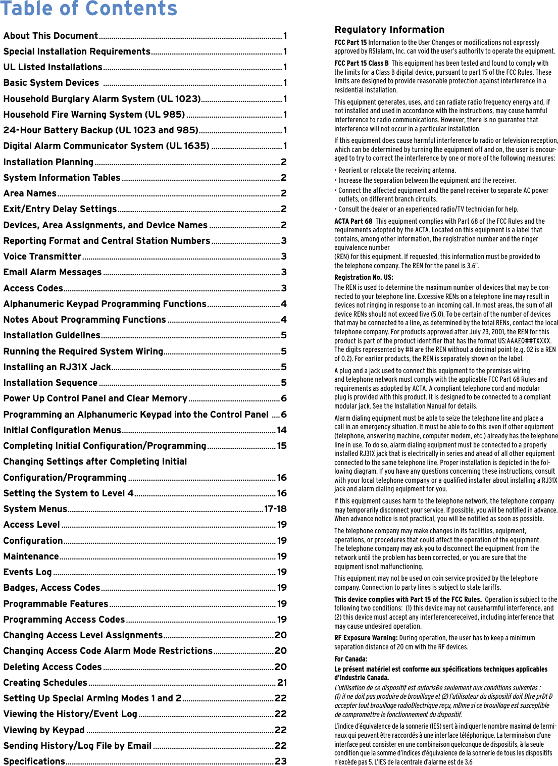
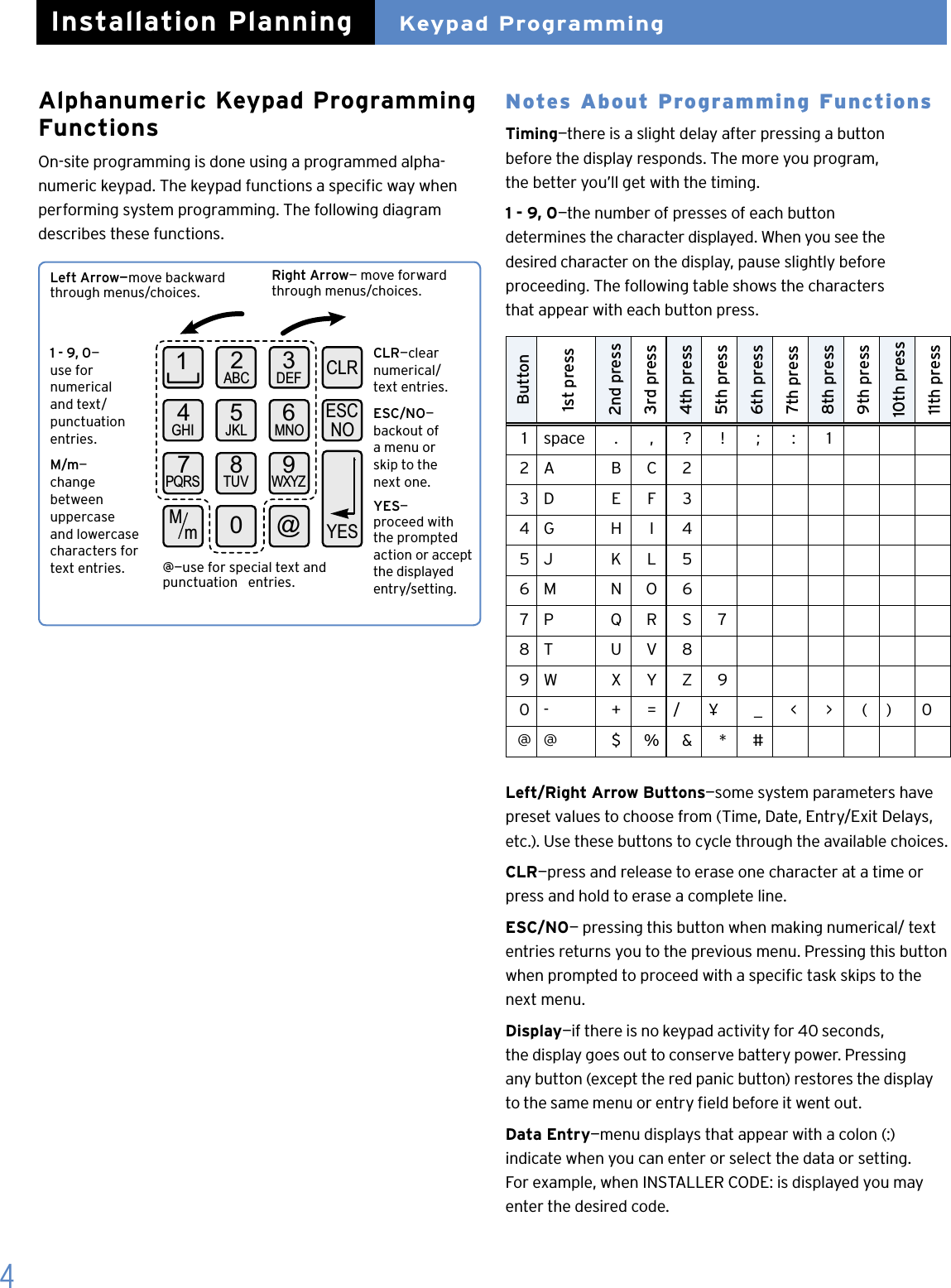
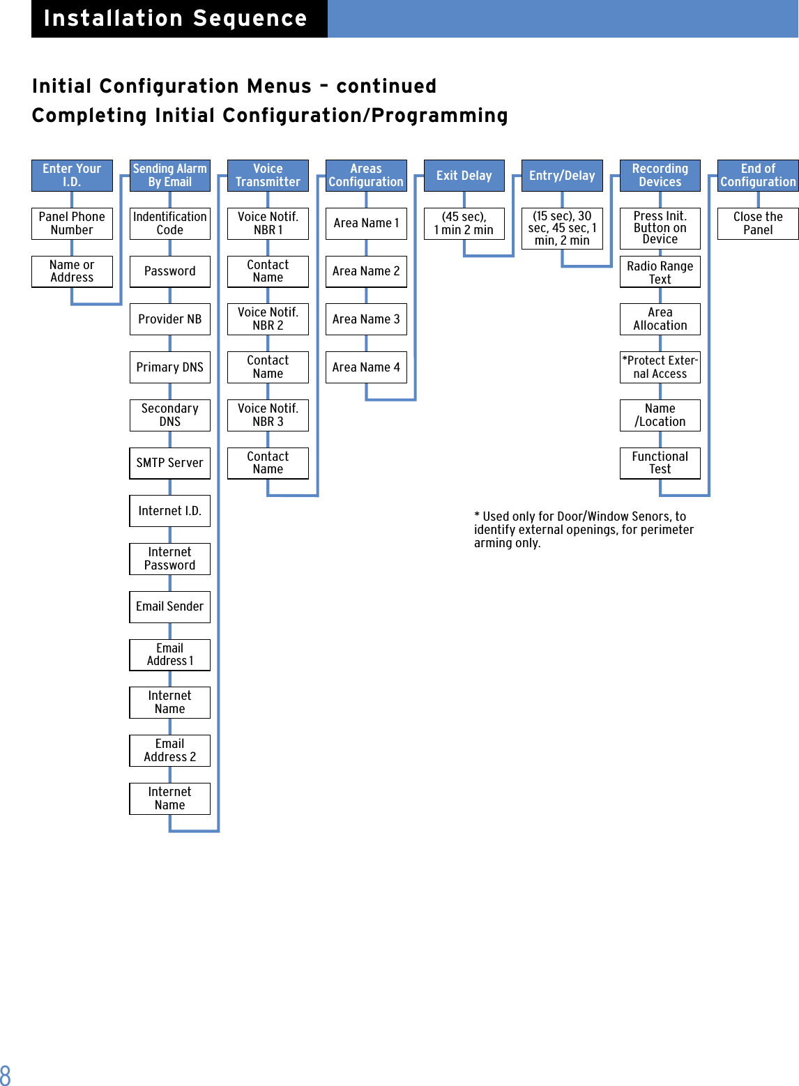
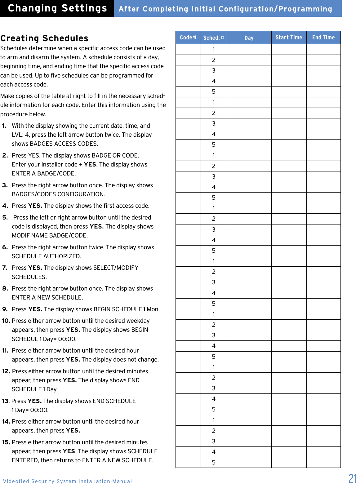
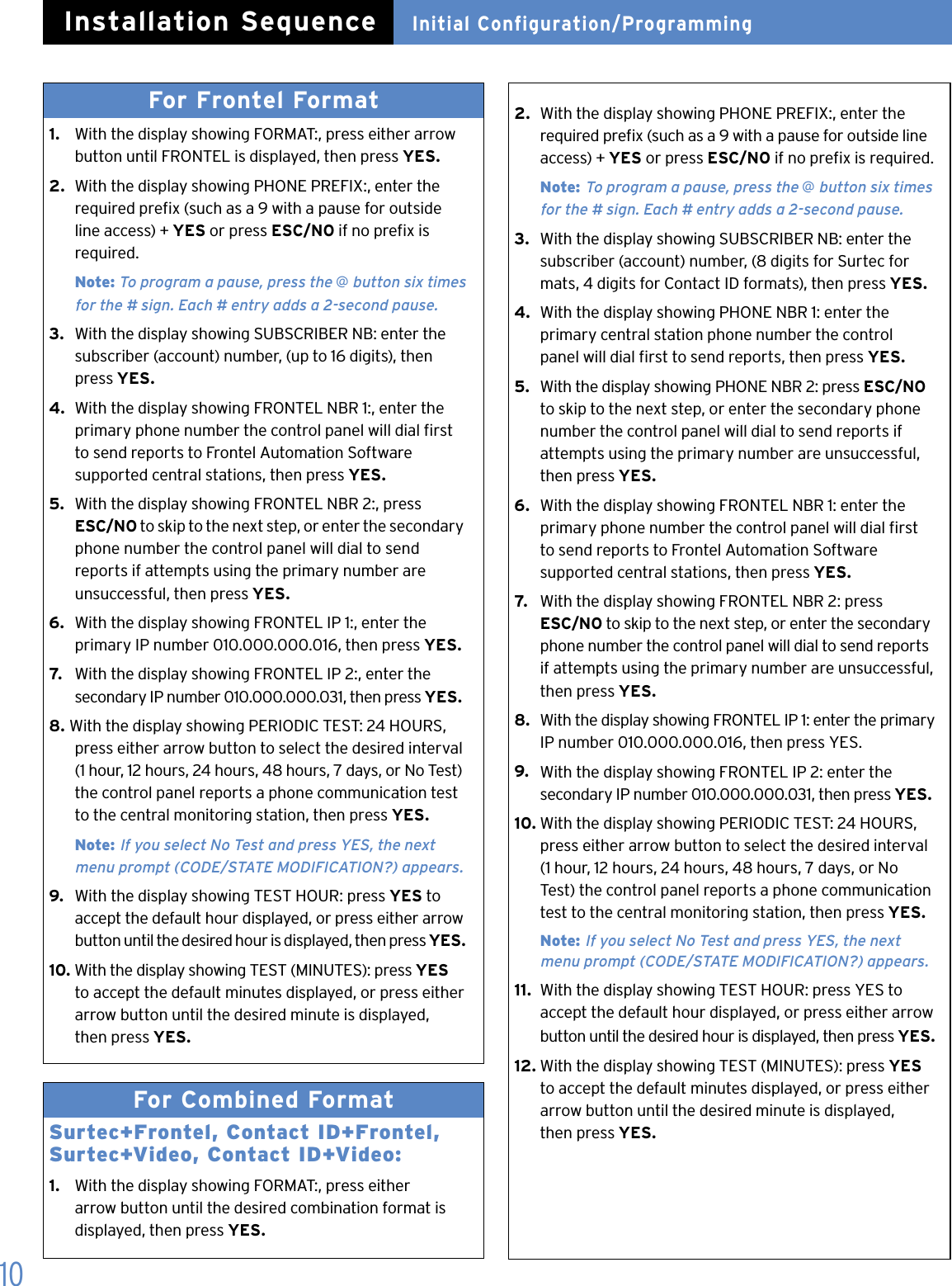
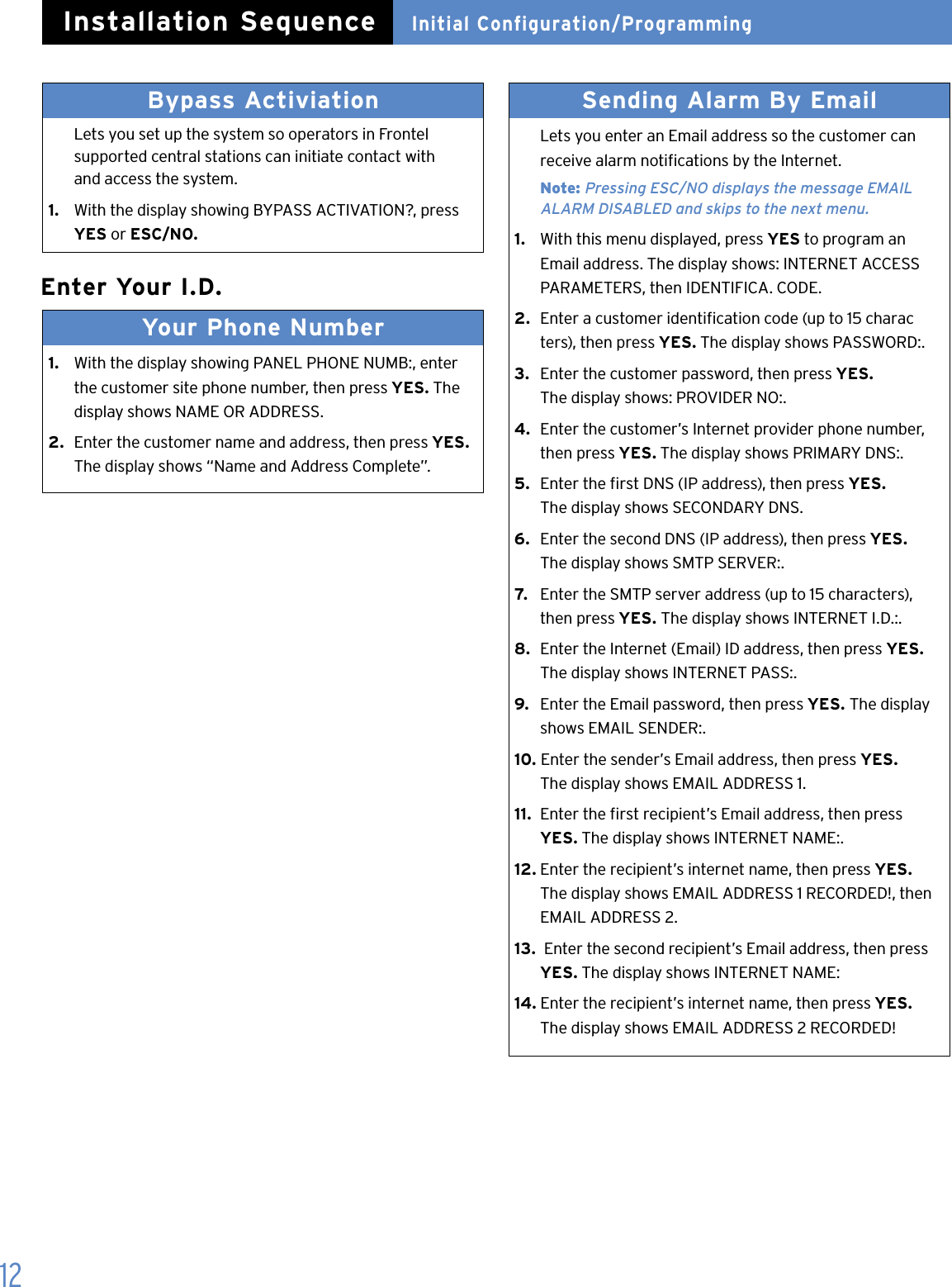
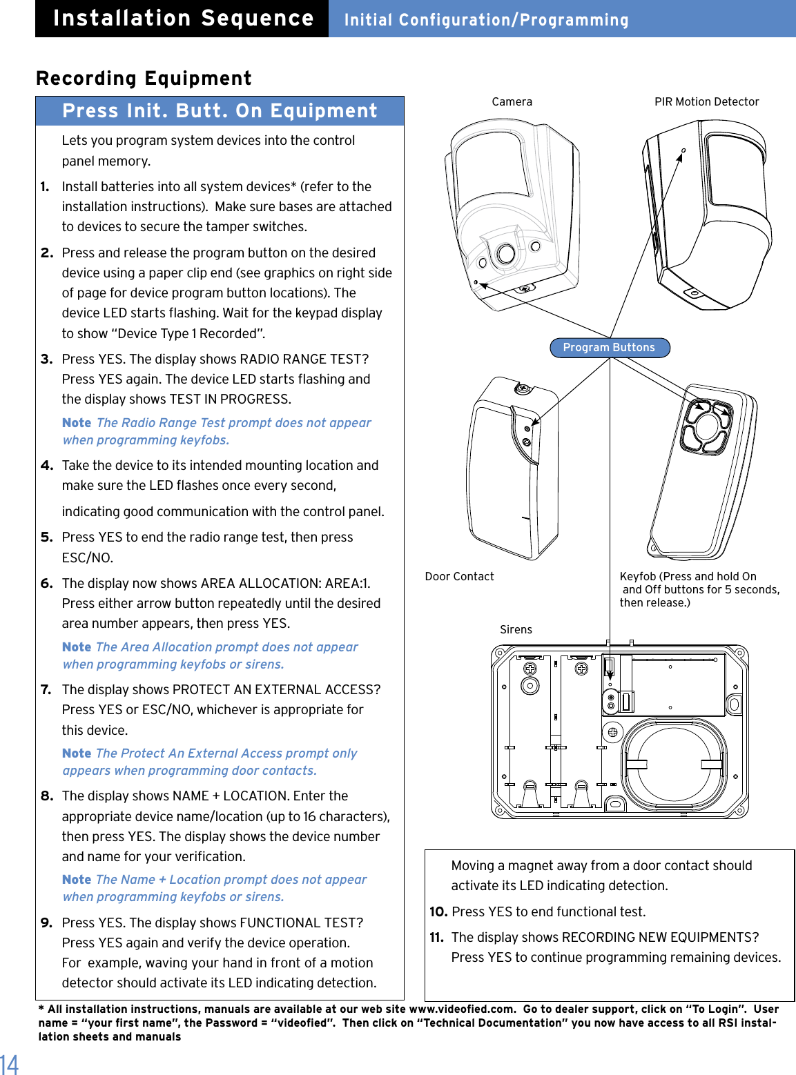
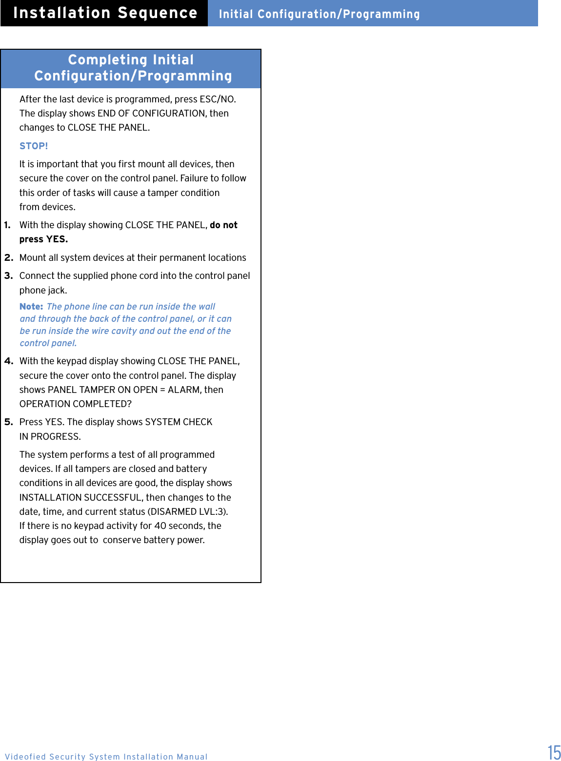
![9Installer CodeLets you program a code that is used for all programming and maintenance functions. The installer code cannot arm/disarm the system. Note: An installer code must be programmed in order to program user access codes.1. With the display showing INSTALLER CODE: enter the desired code, then press YES. The display shows CONFIRM CODE.2. Re-enter the code and press YES. The display shows CODE NAME.3. Enter a name for the installer code using the alphanumeric buttons (up to 16 characters), then press YES. The display shows “Install Entry Complete”. Adjusting Time and DateInitial Configuration/ProgrammingInstallation SequenceData and Time 1. With the display showing DATE (Year):, press the left or right arrow button repeatedly until the correct year number is displayed, then press YES.2. With the display showing DATE (Month):, press the left or right arrow button repeatedly until the correct month number is displayed, then press YES.3. With the display showing DATE (Day):, press the left or right arrow button repeatedly until the correct day number is displayed, then press YES.4. With the display showing DATE (Hour):, press the left or right arrow button repeatedly until the correct hour number is displayed, then press YES.5. With the display showing DATE (Minutes):, press the left or right arrow button repeatedly until the correct minutes number is displayed, then press YES. The display shows the programmed time and date RECORDED. Then display shows “Entry Complete”. Format Lets you set up the system for reporting to a central moni-toring station. The format selection determines how much information must be programmed.For Surtec and Contact ID formats:1. With the display showing FORMAT: press either arrow button until SURTEC or CONTACT ID is displayed, then press YES.2. With the display showing PHONE PREFIX: enter the required prex (such as a 9 with a pause for outside line access) + YES or press ESC/NO if no prex is required. Note: To program a pause, press the @ button six times for the # sign. Each # entry adds a 2-second pause.3. With the display showing Account Number: enter the subscriber (account) number (8 digits for Surtec, 4 digits for Contact ID), then press YES.4. With the display showing PHONE NBR 1: enter the primary central station phone number the control panel will dial rst to send reports, then press YES.5. With the display showing PHONE NBR 2: press ESC/NO to skip to the next step, or enter the secondary phone number the control panel will dial to send reports if attempts using the primary number are unsuccessful, then press YES.6. With the display showing PERIODIC TEST: 24 HOURS, press either arrow button to select the desired interval (1 hour, 12 hours, 24 hours, 48 hours, 7 days, or No Test) the control panel reports a phone communication test to the central monitoring station, then press YES. Note: If you select No Test and press YES, the next menu prompt (CODE/STATE MODIFICATION?) appears.7. With the display showing TEST HOUR: press YES to accept the default hour displayed, or press either arrow button until the desired hour is displayed, then press YES.8. With the display showing TEST (MINUTES): press YES to accept the default minutes displayed, or press either arrow button until the desired minute is displayed, then press YES.Videofied Security System Installation ManualConnected To Monitor Station? [YES = continue, ESC/NO = skip]](https://usermanual.wiki/RSIAlarm/TE00/User-Guide-925930-Page-11.png)
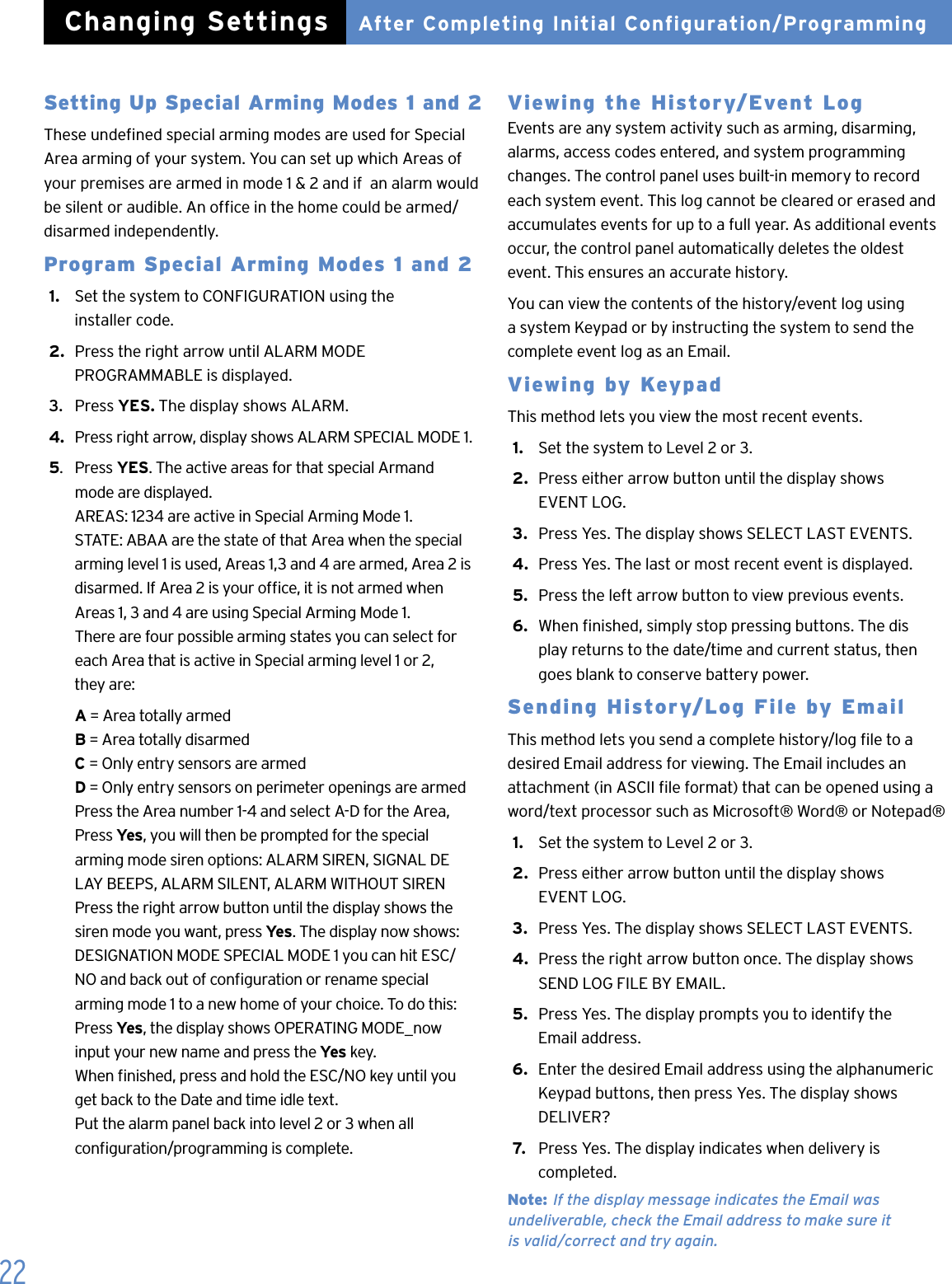
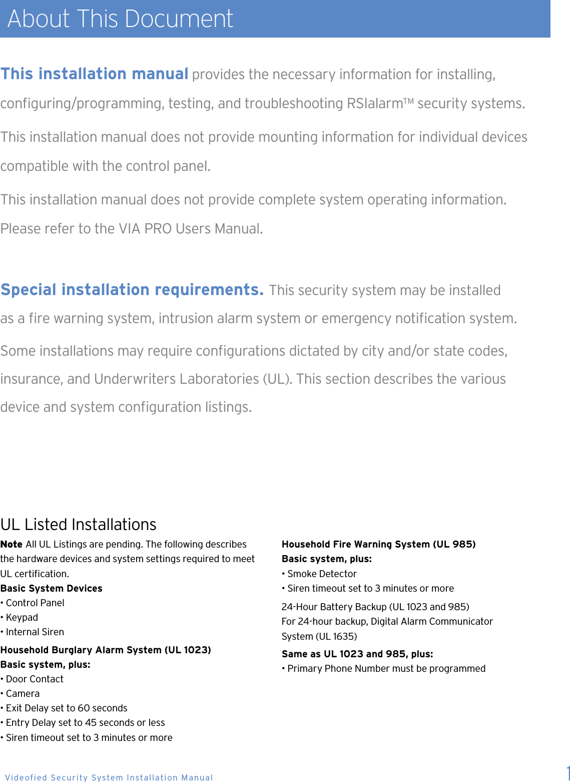
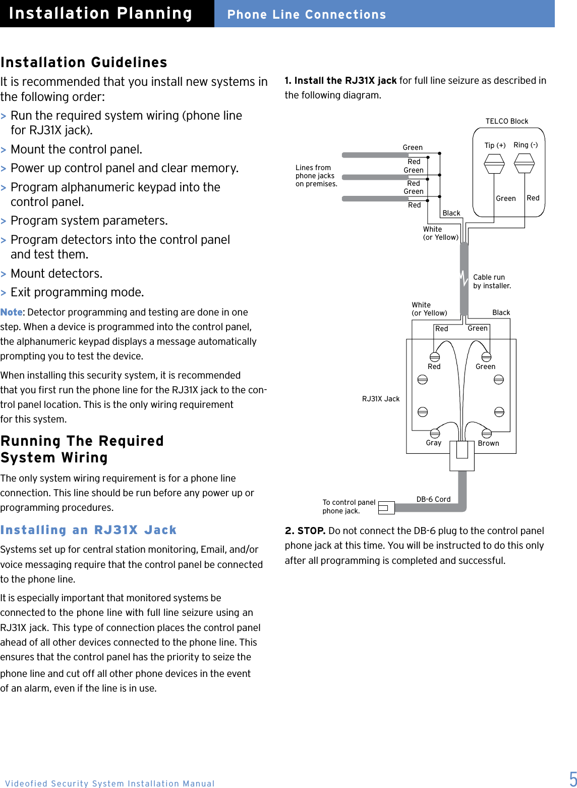
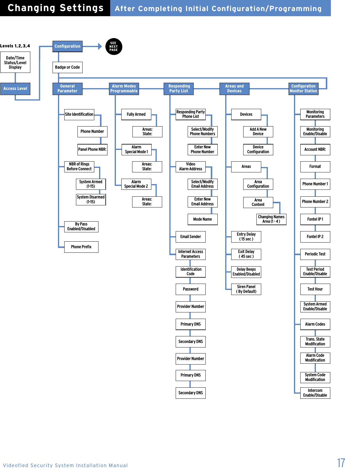
![11Code/State Modification? [YES = continue, ESC/NO = skip]Tran. State Modification Lets you change the control panel default settings for how and/or whether certain conditions are reported to the central station. There are three possible settings for each state: Alarm—alarm reports only Alarm/End—alarm and restore reports No Trans—no report There are 15 states described below with their default setting that can be changed. > DEVICE—Alarm > ALERT —Alarm > INITIALIZATION —No Trans > PANEL BATTERIES—No Trans > AC POWER—No Trans > PHONE LINE FAULT—No Trans > TAMPER—Alarm/End > DEVICE BATT.—No Trans > RADIO JAMMING—No Trans > SUPERVISION—No Trans > PERIODIC TEST—Alarm > WRONG CODES—No Trans > DURESS CODE—No Trans > ALARM MEMORY—No Trans > ARM/DISARM—No Trans1. With the display showing TRANS. STATE MODIFICATION: press Yes. The display shows the rst state/setting DETECTOR ALARM.2. Press YES to change this setting or press either arrow button until the desired state/setting is displayed, then press YES. A colon (:) appears indicating that you may now change the current setting.3. Press either arrow button until the desired setting appears, then press YES. The colon disappears and the the new setting is displayed.4. Repeat steps 2 and 3 for all other setting changes.5. When all desired changes are done, press ESC/NO. The display returns to TRANS. STATE MODIFICATION.6. Press the right arrow button once. The display shows ALARM CODE MODIFICATION. Alarm Code Modification Lets you change the default alarm reporting code of each system device. Note: Although this menu appears at this point in the cycle, pressing YES produces the display message NO EQUIPMENTS RECORDED. After devices (equipment) and all initial system programming are programmed (recorded) into control panel memory, you must start a new programming session to modify these codes.System Code Modification Lets you change the system codes the control panel reports to the central station. There are 16 codes described below with their default settings that can be changed. > ALERT—code 120 > INITIALIZATION—code 305 > BATTERY FAULT—code 302 > BATTERY RESTORE—code 302 > AC POWER—code 301 > PHONE LINE FAULT—code 351 > TAMPER—code 383 > DEVICE BATTERY—code 384 > RADIO JAMMING—code 344 > SUPERVISION—code 355 > PERIODIC TEST—code 602 > WRONG CODES—code 461 > DURESS CODE—code 121 > ALARM MEMORY—code 624 > ARMING—code 400 > DISARMING—code 4001. With the display showing ALARM CODE MODIFICATION, press the right arrow button once. The display shows SYSTEM CODE MODIFICATION.2. Press YES. The display shows ALERT CODE 1203. Press either arrow button until the desired system code is displayed, then press YES. A colon (:) appears indicating that you may now change the current setting.4. Enter the desired 3-digit code, then press YES. The colon disappears and the new setting is displayed.5. Repeat steps 3 and 4 for all other setting changes.6. When all desired changes are done, press ESC/NO. The display returns to SYSTEM CODE MODIFICATION. Initial Configuration/ProgrammingInstallation SequenceVideofied Security System Installation Manual](https://usermanual.wiki/RSIAlarm/TE00/User-Guide-925930-Page-13.png)
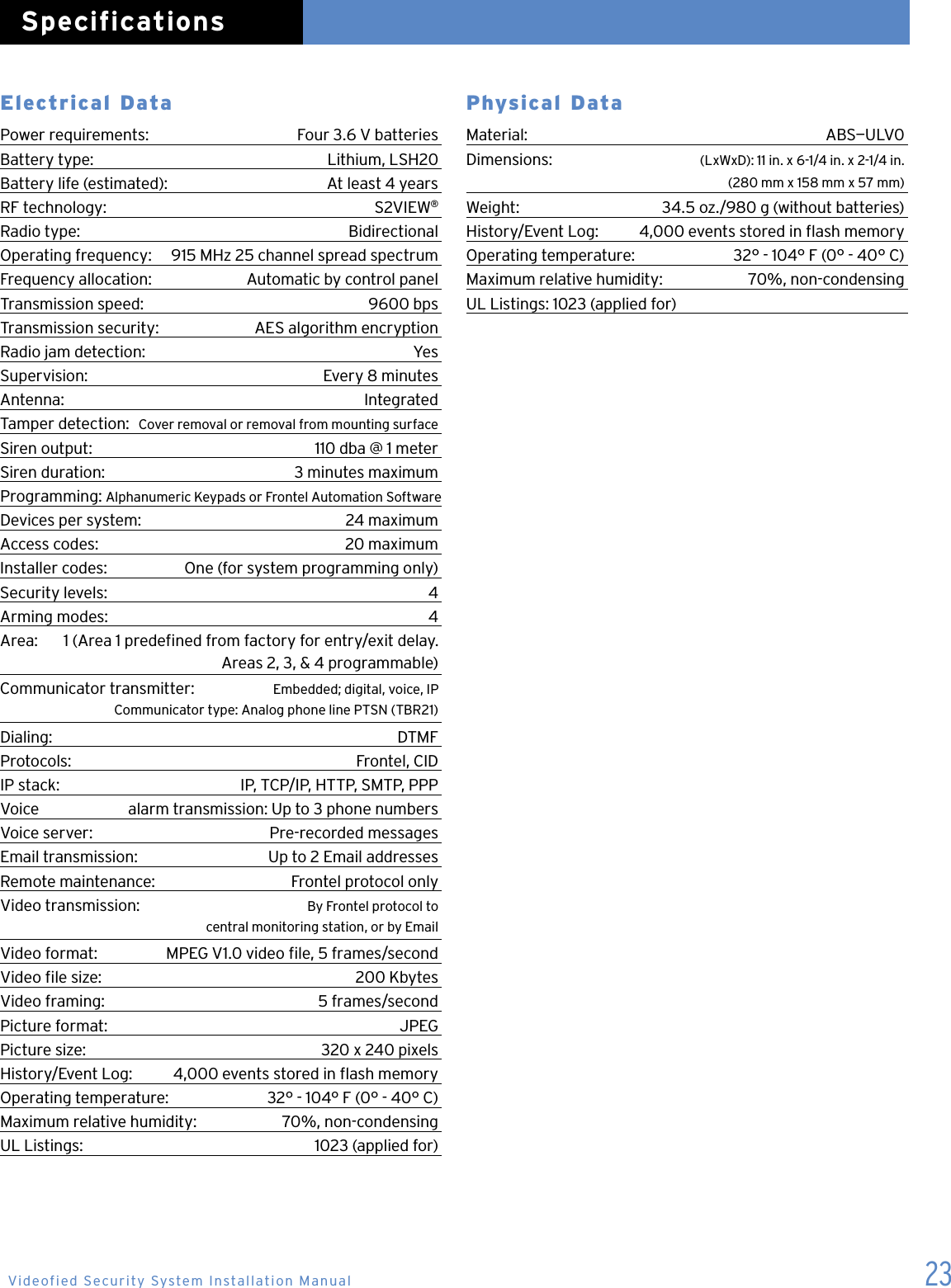
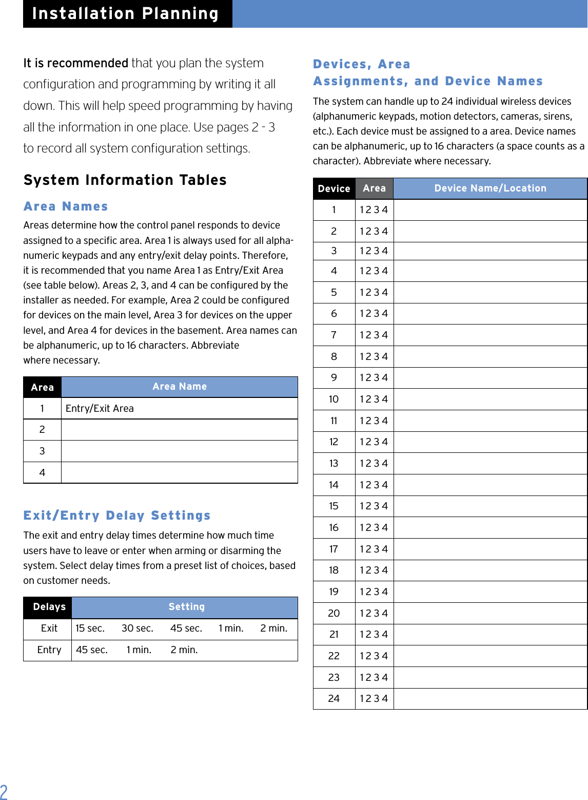
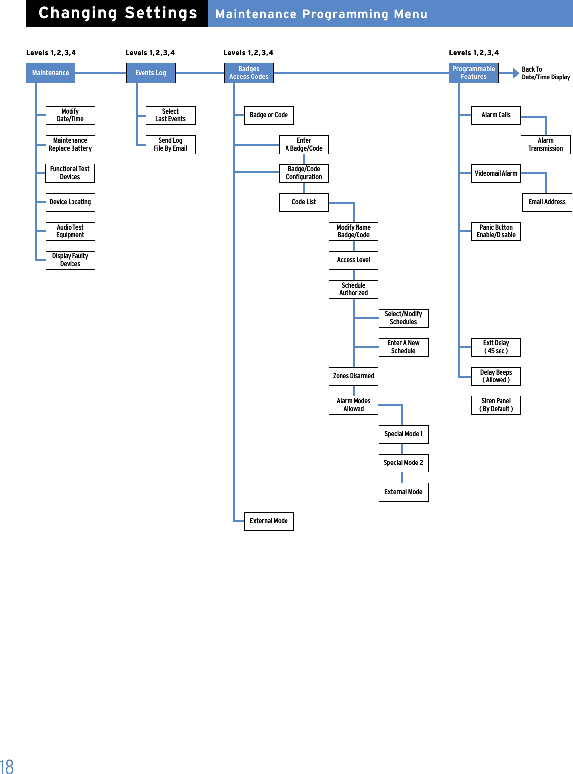
![13Area ConfigurationUsing The Voice Transmitter Lets you set up the system for voice reporting to as many as three customer designated phone numbers. The report includes the device, zone, alarm type, time, and date. During an alarm, the control panel makes three attempts using the rst phone number. If all attempts are unsuccessful, the control panel waits for one minute and makes three more attempts using the second phone number. If these attempts are unsuccessful, the control panel waits for one minute and makes three more attempts using the third phone number. Follow these steps to enter the destination phone numbers, contact /recipient names, passwords, and name assigned to each password. Note: Pressing ESC/NO displays the message VOICE TRANS. DISABLED and skips to the next menu.1. With this menu displayed, press YES to set up the voice transmitter. The display shows VOICENOTIF . PHONE NBR 1:.2. Enter the rst phone number destination, then press YES. The display shows CONTACT NAME.3. Enter the appropriate contact name, then press YES. The display shows “Entry Complete”, then VOICENOTIF . PHONE NBR 2:. Note: If only programming one voice transmitter number, press ESC/ NO to skip programming the next two voice transmitter numbers.4. Enter the second phone number destination, then press YES. The display shows CONTACT NAME:.5. Enter the second appropriate contact name, then press YES. The display shows “Entry Complete”, then VOICENOTIF . PHONE NBR 3:. Note: If only programming two voice transmitter numbers, press ESC/NO to skip programming the third voice transmitter number.6. Enter the third phone number destination, then press YES. The display shows CONTACT NAME:.7. Enter the third appropriate contact name, then press YES. The display shows “Entry Complete”.Area Name 1 Lets you name each of the four areas used for identifying the different areas of the installation. Area 1 is predened from the factory for alphanumeric keypads and any entry/exit delay points. Area 1 should be named appropriately to identify it as the delay area. Areas 2, 3, and 4 have no predened default properties and can be named as required for the installation. For example, Area 2 could be congured and named as Main Level, Area 3 Upper Level, and Area 4 Basement.1. With the display showing AREA NAME 1: enter the desired name, then press YES. The display shows [NAME], AREA 1 RECORDED, then AREA NAME 2.2. Enter the desired area 2 name, then press YES. The display shows [NAME], AREA 2 RECORDED, then AREA NAME 3.3. Enter the desired area 3 name, then press YES. The display shows [NAME], AREA 3 RECORDED, then AREA NAME 4.4. Enter the desired area 4 name, then press YES. The display shows [NAME], AREA 4 RECORDED. Exit Delay Determines the amount of time users have to leave through a delay door without causing an alarm. Note: For UL Listed installations, the Exit Delay must be set to 60 seconds or less. > With the display showing EXIT DELAY: 45 sec, press YES to accept the default setting, or press either arrow button until the desired exit delay time appears (45 sec, 1 min, or 2 min), then press Yes.Entry Delay Determines the amount of time users have to disarm the system upon entry, before an alarm occurs. Note: For UL Listed installations, the Entry Delay must be set to 45 seconds or less. > With the display showing ENTRY DELAY: 15 sec, press YES to accept the default setting, or press either arrow button until the desired entry delay time appears (15 sec, 30 sec, 45 sec, 1 min, or 2 min), then press Yes.Initial Configuration/ProgrammingInstallation SequenceVideofied Security System Installation Manual](https://usermanual.wiki/RSIAlarm/TE00/User-Guide-925930-Page-15.png)
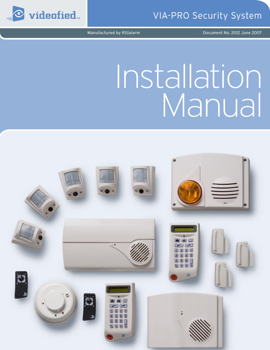
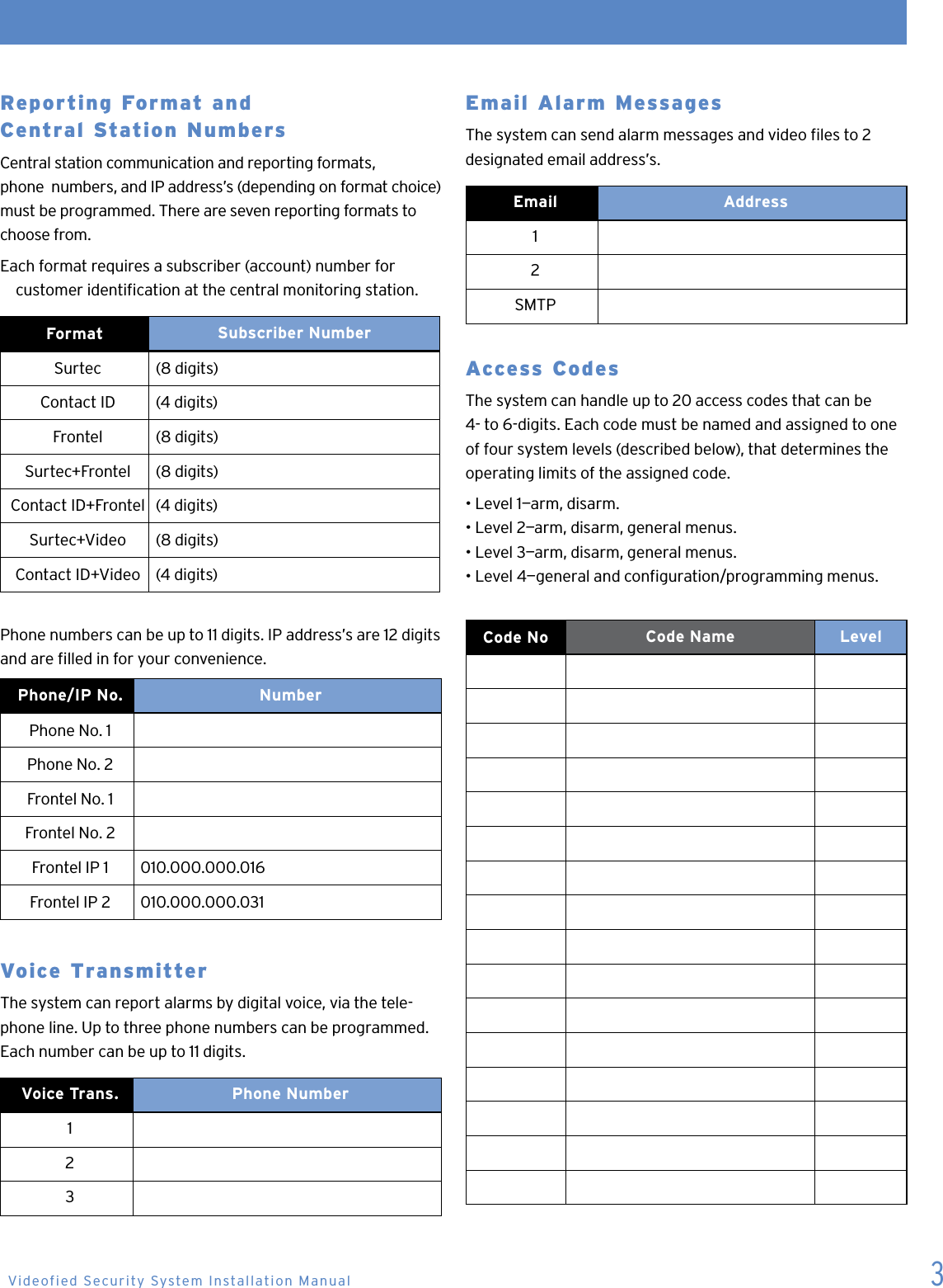
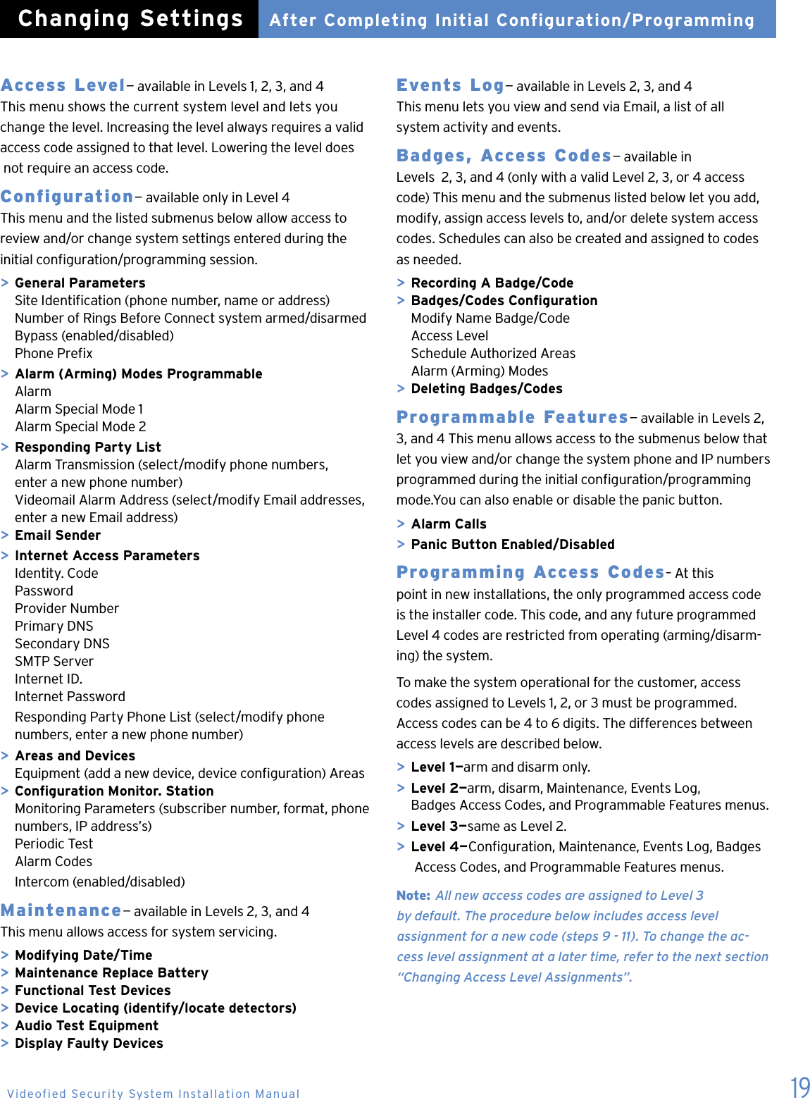
![16Changing Settings After Completing Initial Conguration/Programmin Once the control panel cover is secured in place, removing it causes a tamper alarm. Changing settings made during the initial conguration or adding devices now requires setting the system to Access Level 4, using your installer code. Setting the System to Level 41. With the display showing [DATE/ TIME], DISARMED LEVEL:3, press the right arrow button once. The display shows ACCESS LEVEL 3.2. Press YES. The display now shows a colon (:) between LEVEL and 3 (LEVEL:3).3. Press the right arrow button once to change the level number to 4, then press YES. The display shows BADGE OR CODE.4. Enter your installer code, then press YES. The display shows ACCESS LEVEL 4. You can now access the following menus: > Conguration > Maintenance > Event Log > Badges-Access codes > Programmable FeaturesTo make changes press the arrow keys to go to the desired menu and press YES. Only the Conguration & Badges-Ac-cess Codes menus require an access code to enter to view or change data. Review the system menus on the next few pages to see the programmable options.System Menus The next two pages show the order in which menus now appear with the system in operational mode. There are six main menus available in the operating mode. The system level determines which menus are available, some with their own set of submenus. The main menus and submenus are described afterward. To access these menus, press either arrow button until the desired main menu is displayed, then press YES to proceed.After Completing Initial Configuration/ProgrammingChanging Settings](https://usermanual.wiki/RSIAlarm/TE00/User-Guide-925930-Page-18.png)
![20 1. With the display showing the current date, time, and LVL:4, press the left arrow button twice. The display shows BADGES ACCESS CODES.2. Press YES. The display shows BADGE OR CODE. Enter your installer code + YES. The display shows RECORDING A BADGE/CODE.3. Press YES. The display shows BADGE OR CODE.4. Enter the desired code + YES. The display shows CONFIRM THE CODE.5. Re-enter the code + YES. The display shows CODE NAME:.6. Enter the desired name + YES. The display shows [NAME] ENTRY COMPLETE, then returns to RECORDING A BADGE/CODE.7. Press the right arrow button once. The display shows BADGES/CODES CONFIGURATION.8. Press YES. The display shows MODIF NAME BADGE CODE.9. Press the right arrow button once. The display shows ACCESS LEVEL 3.10. Press YES. The display now shows a colon (:) between LEVEL and 3.11. Press either arrow button until the desired level is displayed, then press YES. The display shows the new level assignment.12. Press ESC/NO three times to return to BADGES ACCESS CODES.13. Repeat steps 2 - 12 for remaining codes.Changing Access Level Assignments You can change the access level assignments as needed any-time, using the following steps.1. With the display showing the current date, time, and LVL: 4, press the left arrow button twice. The display shows BADGES ACCESS CODES.2. Press YES. The display shows BADGE OR CODE. Enter your installer code + YES. The display shows ENTER A BADGE/CODE.3. Press the right arrow button once. The display shows BADGES/CODES CONFIGURATION.4. Press YES. The display shows the rst programmed access code.5. Press either arrow button until the desired code appears, then press YES. The display shows MODIF NAME BADGE/CODE.6. Press the right arrow button once. The display shows ACCESS LEVEL 3.7. Press YES. The display now shows a colon (:) between LEVEL and 3.8. Press either arrow button until the desired level assignment appears, then press YES. The display shows the new level assignment.9. Press ESC/NO.10. Repeat steps 5 - 9 for other level assignment changesChanging Access Code Alarm Mode Restrictions– After programming a new access code, altering alarm (arming) modes for any access code, using the following steps.1. With the display showing date, time and LVL 4, press the left arrow button twice. The display shows BADGES ACCESS CODES.2. Press YES. The display shows BADGE OR CODE. Enter a Level 2 or 3 access code + YES. The display shows ENTER A BADGE/CODE.3. Press the right arrow button once. The display shows BADGES/CODES CONFIGURATION.4. Press YES. The display shows the rst programmed access code.5. Press either arrow button until the desired code appears, then press YES. The display shows MODIFY NAME BADGE/CODE.6. Press the left arrow button once. The display shows ALARM MODES ALLOWED.7. Press YES. The display shows SPECIAL MODE 1 ALLOWED.8. Press either arrow button until the desired mode appears, then press YES. The display shows a colon (:) next to ALLOWED.9. Press either arrow button once. The display changes to DISABLED.10. Press YES. The display shows the new alarm (arming) mode setting without the colon.11. Repeat steps 5 - 10 for other code restriction changes.Deleting Access Codes– Delete access codes as needed anytime, using the following steps.1. With the display showing the current date, time, and LVL: 4, press the left arrow button twice. The display shows BADGES ACCESS CODES.2. Press YES. The display shows BADGE OR CODE. Enter your installer code + YES. The display shows ENTER A BADGE/CODE.3. Press the left arrow button once. The display shows DELETING BADGES/CODES.4. Press YES. The display shows the rst programmed access code.5. Press either arrow button until the desired code appears, then press YES. The display shows DELETING CODE.6. Press YES again. The display shows CODE DELETED.7. Repeat steps 5 - 6 to continue deleting codes.After Completing Initial Configuration/ProgrammingChanging Settings](https://usermanual.wiki/RSIAlarm/TE00/User-Guide-925930-Page-22.png)