RTX CT8015 1.9GHz DECT VoIP and PSTN Gateway User Manual
RTX Hong Kong Ltd. 1.9GHz DECT VoIP and PSTN Gateway Users Manual
UserManual.wiki
>
RTX
>
CT8015 User Manual
Users Manual
Navigation menu
Upload a User Manual
Namespaces
Wiki Guide
HTML
PDF
Info
Views
User Manual
Discussion / Help
Navigation

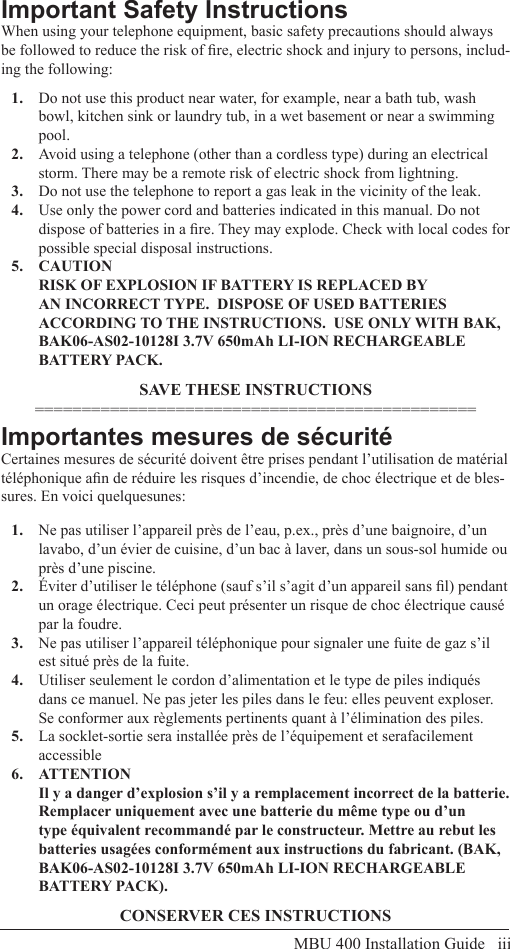
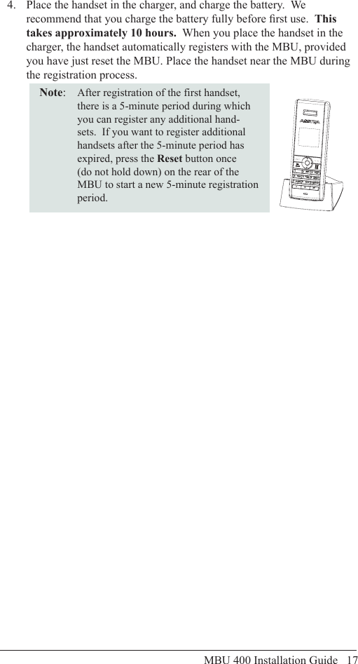
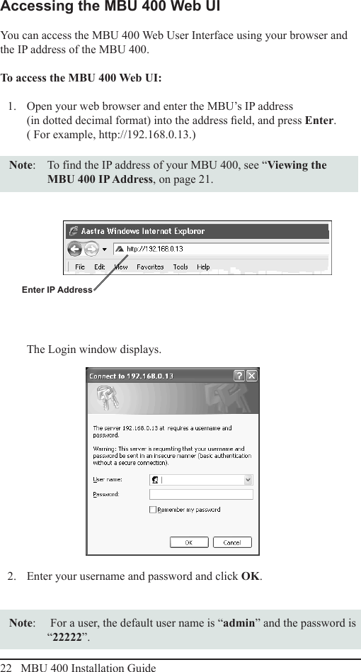
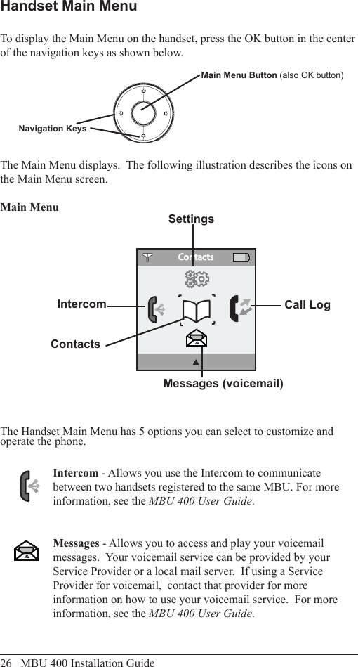
![viii MBU 400 Installation GuideCAUTION: Users should not attempt to make such connections themselves, but should contact the appropriate electric inspection authority, or electrician, as appropriate.‘’The Ringer Equivalence Number is an indication of the maximum number of terminals allowed to be connected to a telephone interface. The termina-tion on an interface may consist of any combination of devices subject only to the requirement that the sum of the Ringer Equivalence Numbers of all the devices does not exceed ve.’’Le présent materiel est conforme aux specications techniques applicables d’Industrie Canada. L’indice d’équivalence de la sonnerie (IES) sert à indiquer le nombre maximal de terminaux qui peuvent être raccordés à une interface téléphonique. La terminaison d’une interface peut consister en une combinaison quelconque de dispositifs, à la seule condition que la somme d’indices d’équivalence de la sonnerie de tous les dispositifs n’excède pas 5.Consumer Informationa) This equipment complies with Part 68 of the FCC rules and the requirements adopted by the ACTA. On the back of this equipment is a label that contains, among other information, a product identier in the format US:T7HIP06B8015. If requested, this number must be provided to the telephone company.b) An applicable certication jacks Universal Service Order Codes (USOC) for the equipment is provided (i.e., RJ11C) in the packaging with each piece of approved terminal equipment. c) A plug and jack used to connect this equipment to the premises wiring and telephone network must comply with the applicable FCC Part 68 rules and requirements adopted by the ACTA. A compliant telephone cord and modular plug is provided with this product. It is designed to be connected to a compatible modular jack that is also compliant. See installation instructions for details.d) The REN is used to determine the number of devices that may be connected to a telephone line. Excessive RENs on a telephone line may result in the devices not ringing in response to an incoming call. In most but not all areas, the sum of RENs should not exceed ve (5.0). To be certain of the number of devices that may be connected to a line, as determined by the total RENs, contact the local telephone company. [For products approved after July 23, 2001, the REN for this product is part of the product identier that has the format US:T7HIP06B8015. The digits represented by ## are the REN without a decimal point (e.g., 06 is a REN of 0.6). For earlier products, the REN is separately shown on the label.]FCC Information](https://usermanual.wiki/RTX/CT8015/User-Guide-1011351-Page-8.png)