RTX X8665 Multicell Base User Manual 2 User Guide V0 1 okx
RTX Hong Kong Ltd. Multicell Base 2 User Guide V0 1 okx
RTX >
User Manual

SMEVOIPS
Y
Proprietary
a
Quickstar
t
Installatio
Trademarks
Y
STEMGUIDE
a
ndConfiden
t
t
guide
n&Configu
4.1
t
ial
T
ration
T
ype
Technic
a
©August
‐
App
a
lReference
D
Version1.0
‐
2018RTXA/
S
rov
a
D
ocument
S
,Denmark
a
l Us
e
e
r G
u
u
id
e
e

SMEVOIPSYSTEMGUIDE4.1
ProprietaryandConfidential
RTXandthecombinationsofitslogothereofaretrademarksofRTXA/S,Denmark.
Otherproductnamesusedinthispublicationareforidentificationpurposesandmaybethetrademarksoftheir
respectivecompanies.
Disclaimer
ThecontentsofthisdocumentareprovidedaboutRTXproducts.RTXmakesnorepresentationswithrespectto
completenessoraccuracyofthecontentsofthispublicationandreservestherighttomakechangestoproduct
descriptions,usage,etc.,atanytimewithoutnotice.Nolicense,whetherexpress,implied,toanyintellectualproperty
rightsaregrantedbythispublication
Confidentiality
Thisdocumentshouldberegardedasconfidential,unauthorizedcopyingisnotallowed
©August‐2018RTXA/S,Denmark,Allrightsreserved
http://www.rtx.dk

SMEVOIPSYSTEMGUIDE4.1
ProprietaryandConfidential
TableofContents
TypeApprovalUserGuideforDBS‐210‐3PC‐NA‐K9...........................................................................................................1
1AboutThisDocument.................................................................................................................................................4
1.1Audience...........................................................................................................................................................4
1.2WhenShouldIReadThisGuide........................................................................................................................4
1.3ImportantAssumptions.....................................................................................................................................4
1.4Abbreviations....................................................................................................................................................4
1.5DocumentHistory.............................................................................................................................................4
1.6DocumentationFeedback.................................................................................................................................4
2Introduction–SystemOverview................................................................................................................................5
2.1HardwareSetup................................................................................................................................................5
2.2ComponentsofSMEVoIPSystem.....................................................................................................................6
2.2.1RTXBaseStations..........................................................................................................................................6
2.2.2SMEVoIPAdministrationServer/Software..................................................................................................6
2.2.3RTXWirelessHandset...................................................................................................................................6
2.3WirelessBands..................................................................................................................................................6
2.4SystemCapacity(inSummary)..........................................................................................................................7
2.5AdvantagesofSMEVoIPSystem.......................................................................................................................7
3InstallationofBaseStations/Repeater.......................................................................................................................8
3.1Package–Contents/DamageInspection...........................................................................................................8
3.2RTXBaseStationMechanics.............................................................................................................................9
3.3RTXBaseUnit–Resetfeature.........................................................................................................................10
3.4InstallingtheBaseStation...............................................................................................................................11
3.4.1MountingtheBaseStations/Repeaters:.....................................................................................................11
3.5FindIPofBaseStation.....................................................................................................................................11
3.5.1UsinghandsetFindIPfeature.....................................................................................................................11
3.5.2UsingbrowserIPDECT.................................................................................................................................11
3.6LogintoBaseSMEConfigurationInterface.....................................................................................................11
4MakingHandsetReady.............................................................................................................................................12
4.1Package–Contents/DamageInspection.........................................................................................................12
4.2BeforeUsingthePhone..................................................................................................................................13

DBS‐210‐3PC‐NA‐K9TYPEAPPROVALUSERGUIDE1.0
4|Page
ProprietaryandConfidential
1 AboutThisDocument
ThisdocumentdescribestheinstallationandconfigurationoftheCiscoVoIPSystem(DBS‐210‐3PC‐NA‐K9base,CP‐
6825‐3PC‐K9,CP‐6825‐3PC‐NA‐K9,CP‐6825‐RGD‐K9,CP‐6825‐RGD‐NA‐K9handset).
1.1 ImportantAssumptions
Thisdocumentwaswrittenwiththefollowingassumptionsinmind:
1) Youunderstandnetworkdeploymentingeneral
2) YouhaveworkingknowledgeofbasicTCP/IP/SIPprotocols,NetworkAddressTranslation,etc...
3) Apropersitesurveyhasbeenperformed,andtheadministratorhaveaccesstotheseplans
1.2 Abbreviations
Forthisdocument,thefollowingabbreviationshold:
DHCP:DynamicHostConfigurationProtocol
DNS: DomainNameServer
HTTP(S): HyperTextTransferProtocol(Secure)
(T)FTP:(Trivial)FileTransferProtocol
IOS: InternetworkingOperatingSystem
PCMA:A‐lawPulseCodeModulation
PCMU:mu‐lawPulseCodeModulation
PoE: PoweroverEthernet
RTP:Real‐timeTransportProtocol
RPORT: ResponsePort(RefertoRFC3581fordetails)
SIP:SessionInitiationProtocol
SME: SmallandMediumscaleEnterprise
VLAN:VirtualLocalAccessNetwork
TOS: TypeofService(policybasedrouting)
URL: UniformResourceLocator
UA: UserAgent
1.3 DocumentHistory
REVISIONAUTHORISSUEDATECOMMENTS
0.1CAP16‐Aug‐2018FirstDraft
1.4 DocumentationFeedback
Wealwaysstrivetoproducethebestandwealsovalueyourcommentsandsuggestionsaboutourdocumentation.If
youhaveanycommentsaboutthisguide,pleaseenterthemthroughtheFeedbacklinkontheRTXwebsite.Wewill
useyourfeedbacktoimprovethedocumentation.
DBS‐210‐3P
C
Proprietary
a
2 Intr
o
Inatypicalt
e
repeaters,p
o
topologyis
u
Thesystemi
1000registe
systemsetu
p
otherthant
h
simultaneou
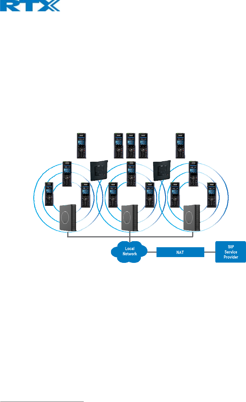
Thefollowin
g
2.1 Har
d
SMEnetwor
k
Base‐station
TheLayer3
r
Thebase‐sta
50mindoor1
tobase‐stati
additionalb
a
Thebase‐sta
usescomple
t
simultaneou
1Measured
w
C
‐NA‐K9TYPE
5|Page
a
ndConfiden
t
o
duction
e
lephonysys
t
o
rtableparts,
u
sed.Thenet
w
seasytoscal
e
redhandsets
p
isillustrate
d
h
eLANcable.
scallsession
s
g
figuregives
d
wareSet
u
k
hardwares
e
(s)areconne
c
r
outerimple
m
tionsaremo
u
(300moutd
o
on(s).Repeat
a
sesmustbe
u
tionantenna
t
eDECTMAC
scalls.
w
ithEuropea
n
APPROVALU
t
ial
–Syste
m
t
em,thenet
w
etc.Thebac
k
w
orkhascent
e
upandsup
p
(RTX8630,R
T
d
below.Base
d
Thesystems
s
.
agraphicalo
v
u
p
e
tupcanbed
e
c
tedviaLaye
r
m
entstheswi
t
u
ntedonwall
o
or).Radioco
v
ersarerange
u
sed.
mechanismi
s
protocollay
e
n
DECTradio
a
SERGUIDE1.
m
Overvi
e
w
orksetupist
k
‐boneofthe
ralizedmonit
p
ortsfrom1t
T
X8830andR
T
d
onPoEinte
r
upportstheI
P
v
erviewofth
e
e
ployedasfo
r
3and/orVL
A
t
chingfuncti
o
sorlamppol
e
v
eragecanb
e
extendersa
n
s
basedonsp
e
randIPmed
i
a
nddepends
0
e
w
heinterconn
e
networkdep
e
oring,andm
a
o249basesi
n
T
X8430).The
S
r
faceeachba
s
P
DECTCAT‐I
Q
e
architectur
e
llows:
A
NAwareRo
u
o
n.
e
ssothatea
c
e
extendedus
n
dcannotbe
u
acediversity
f
i
astreamau
d
onlocalbuil
d
e
ctionbetwe
e
e
ndsonthed
a
intenancesy
n
thesamen
e
S
mallandM
e
s
estationise
Q
repeaterR
T
e
oftheSME
V
u
terdependin
c
hbase‐statio
ingrepeaters
u
sedtosolve
f
eaturewhic
h
ioencodingf
e
d
inglayoutan
d
e
nBase‐stati
o
eployments
c
stem.
e
twork.Furth
e
e
diumScaleE
n
asytoinstall
w
T
X4024withs
u
V
oIPSystem:
gonthedepl
nisseparate
d
thatareinst
a
localcallcap
a
h
improvesco
v
e
aturetopro
v
d
material
o
ns,“fat”rou
t
c
enario,buta
e
ritcansupp
n
terprise(SM
w
ithoutaddi
t
u
pportupto
5
oymentrequ
i
d
fromeacho
t
a
lledwithsa
m
a
cityissues.I
n
v
erage.The
b
v
ideupto10
t
ers,
ringorhub
ortupto
E)VoIP
t
ionalwires
5
channels
i
rements.
t
herbyupto
m
edistance
n
thiscase
b
ase‐stations

DBS‐210‐3PC‐NA‐K9TYPEAPPROVALUSERGUIDE1.0
6|Page
ProprietaryandConfidential
2.2 ComponentsofSMEVoIPSystem
RTXSMEVoIPsystemismadeupof(butnotlimitedto)thefollowingcomponents:
• AtleastoneRTXBaseStationisconnectedoveranIPnetworkandusingDECTasair‐coreinterface.
• RTXIPDECTwirelessHandset.
• RTXSMEVoIPConfigurationInterface;isamanagementinterfaceforSMEVoIPWirelessSolution.ItrunsonallIP
DECTBasestations.EachBasestationhasitsownuniquesettings.
2.2.1 RTXBaseStations
TheBaseStationconvertsIPprotocoltoDECTprotocolandtransmitsthetraffictoandfromtheend‐nodes(i.e.
wirelesshandsets)overachannel.Ithas12availablechannels.
Inamulti‐cellsetup,eachbasestationhas:
• 8channelshaveassociatedDSPresourcesformediastreams.
• Theremaining4channelsarereservedforcontrolsignalingbetweenIPBaseStationsandtheSIP/DECTendnodes
(orphones).
BaseStationsaregroupedintoclusters.WithineachCluster,BaseStationsaresynchronizedtoenableaseamless
handoverwhenausermovesfromonebasestationcoveragetoanother.Forsynchronizationpurposes,itisnot
necessaryforBaseStationstocommunicatedirectlywitheachotherinthesystem.E.g.aBaseStationmayonlyneed
tocommunicatewiththenextinthechain.ItisadvisableforaBaseStationtoidentifymorethanoneBaseStationto
guaranteesynchronizationinthesituationthatoneoftheBaseStationsfails.
The4controlsignalingchannelsareusedtocarrybearersignalsthatenableahandsettoinitiateahandoverprocess.
2.2.2 SMEVoIPAdministrationServer/Software
ThisserverisreferredtoasSMEVoIPConfigurationInterface.
TheSMEVoIPConfigurationInterfaceisawebbasedadministrationpageusedforconfigurationandprogrammingof
thebasestationandrelevantnetworkend‐nodes.E.g.handsetscanberegisteredorde‐registeredfromthesystem
usingthisinterface.
Theconfigurationinterfacecanbeusedasasetuptoolforsoftwareorfirmwaredownloadtobasestations,repeaters
andhandsets.Further,itisusedtocheckrelevantsystemlogsthatcanbeusefultoadministrator.Theselogscanbe
usedtotroubleshootthesystemwhenthesystemfacesunforeseenoperationalissues.
2.2.3 RTXWirelessHandset
Thehandsetisalightweight,ergonomically,andportableunitcompatiblewithWidebandAudio(G.722),DECT,GAP
standard,CAT‐iqaudiocompliant.
Thehandsetincludescolordisplaywithgraphicaluserinterface.Itcanalsoprovidethesubscriberwithmostofthe
featuresavailableforawiredphone,inadditiontoitsroamingandhandovercapabilities.Refertotherelevant
handsetmanualsforfulldetailshandsetfeatures.
2.3 WirelessBands
ThebandssupportedintheSMEVoIParesummarizedasfollows:
Frequencybands:
1880–1930MHz(DECT)
1880–1900MHz(10carriers)Europe/ETSI
1910–1930MHz(10carriers)LATAM
1920–1930MHz(5carriers)US

DBS‐210‐3PC‐NA‐K9TYPEAPPROVALUSERGUIDE1.0
7|Page
ProprietaryandConfidential
2.4 SystemCapacity(inSummary)
SMEnetworkcapacityofrelevantcomponentscanbesummarizedasfollows:
DESCRIPTIONCAPACITY
Min##ofBasesSingleCellSetup1
Max##ofBasesinMulti‐cellSetup(configurable) 50/127/254
Single/MultiCellSetup:Max##ofRepeaters50basesand3repeatersperBase
127basesand1repeaterperBase
254basesand0repeaters
Multi‐cellSetup:TotalMax##ofRepeaters100
Max##ofUsers(SIPregistrations)perBase30
Max##ofUsersperSMEVoIPSystemlimitedto1000
Multi‐cellSetup:Max##ofSynchronizationlevels 24
SingleCellSetup:Max##SimultaneousCalls10perBasestation
Multi‐cellSetup:Max##ofCalls8perBasestation
TotalMax##SimultaneousCalls(Multi‐cellSetup) Limitedto1000
Repeater:Max##ofCalls(Narrowband)5
Repeater:Max##ofCalls(G722)2
QuickDefinitions
SingleCellSetup:SMEtelephonynetworkcomposedofonebasestation
Multi‐cellSetup: Telephonynetworkthatconsistsofmorethanonebasestation
SynchronizationLevel:Istheaircoreinterfacebetweentwobasestations.
2.5 AdvantagesofSMEVoIPSystem
Theyinclude(butnotlimitedto):
1.Simplicity.Integratingfunctionalitiesleadstoreducedmaintenanceandtroubleshooting,andsignificantcost
reductions.
2.Flexibility.Singlenetworkarchitecturecanbeemployedandmanaged.Furthermore,thearchitectureisamenable
todifferentdeploymentscenarios,includingIsolatedbuildingsforin‐buildingcoverage,locationwithco‐located
partners,andlargetomediumscaleenterprisesdeploymentforwidecoverage.
3.Scalability.SMEnetworkarchitecturecaneasilybescaledtotherequiredsizedependingoncustomerrequirement.
4.Performance.Theintegrationofdifferentnetworkfunctionalitiesleadstothecollapseoftheprotocolstackina
singlenetworkelementandtherebyeliminatestransmissiondelaysbetweennetworkelementsandreducesthecall
setuptimeandpacketfragmentationandaggregationdelays.
DBS‐210‐3PC‐NA‐K9TYPEAPPROVALUSERGUIDE1.0
8|Page
ProprietaryandConfidential
3 InstallationofBaseStations/Repeater
Afterplanningthenetwork,nextistodeterminetheproperplacesorlocationtherelevantbasestationswillbe
installed.Therefore,webrieflydescribethehowtoinstallthebasestationinthischapter.
3.1 Package–Contents/DamageInspection
BeforePackageIsOpened:
Examinetheshippingpackageforevidenceofphysicaldamageormishandlingpriortoopening.Ifthereisaproofof
mishandlingpriortoopening,youmustreportittotherelevantsupportcenteroftheregionalrepresentativeor
operator.
ContentsofPackage:
Makesureallrelevantcomponentsareavailableinthepackagebeforeproceedingtothenextstep.
Everyshippedbaseunitpackage/boxcontainsthefollowingitems:
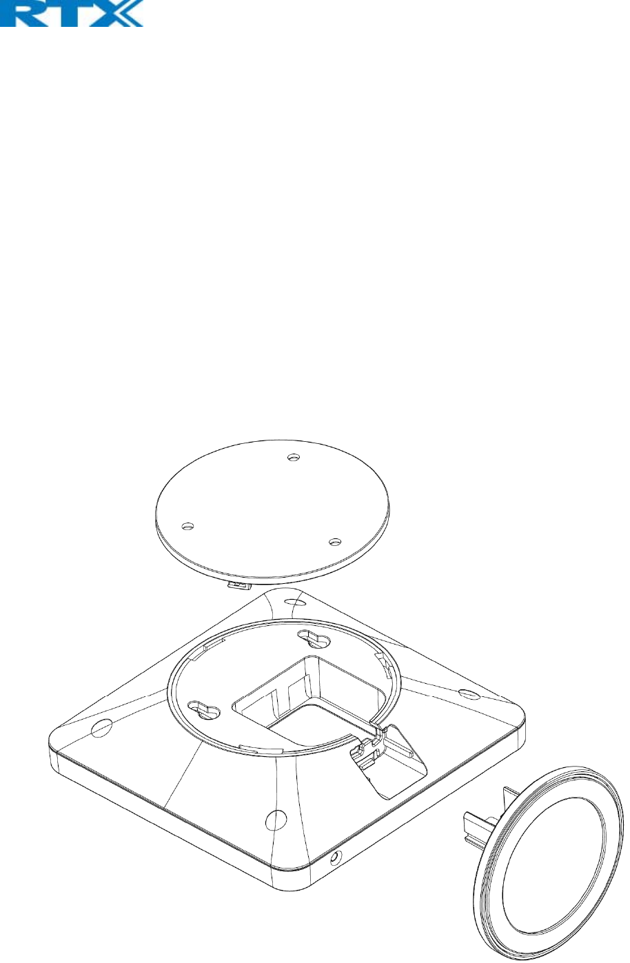
3xmountingscrewsand1xAnchor
1xPlasticWallmount
Baseunit
DBS‐210‐3PC‐NA‐K9TYPEAPPROVALUSERGUIDE1.0
9|Page
ProprietaryandConfidential
DamageInspection:
Thefollowingaretherecommendedprocedureforyoutouseforinspection:
1. Examineallrelevantcomponentsfordamage.
2. Makea“defectiveonarrival–DOA”reportorRMAtotheoperator.Donotmovetheshippingcartonuntil
theoperatorhasexaminedit.Ifpossible,sendpicturesofthedamage.Theoperator/regionalrepresentative
willinitiatethenecessaryproceduretoprocessthisRMA.Theywillguidethenetworkadministratoronhow
toreturnthedamagedpackageifnecessary.
3. Ifnodamageisfound,thenunwrapallthecomponentsanddisposeofemptypackage/carton(s)in
accordancewithcountryspecificenvironmentalregulations.
3.2 RTXBaseStationMechanics
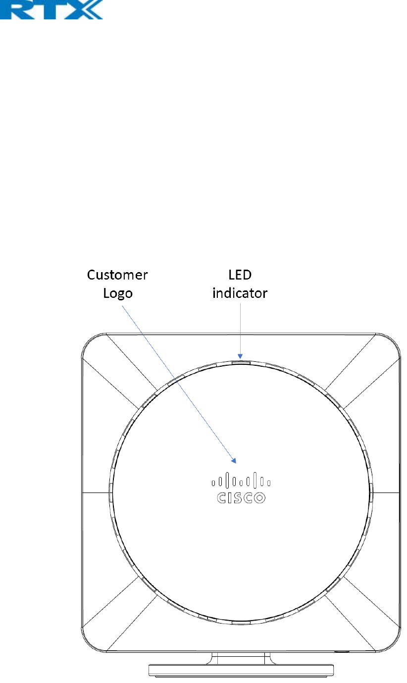
ThebasestationfrontendshowsanLEDindicatorthatsignalsdifferentfunctionalstatesofthebaseunitand
occasionallyoftheoverallnetwork.Theindicatorisoffwhenthebaseunitisnotpowered.
DBS‐210‐3PC‐NA‐K9TYPEAPPROVALUSERGUIDE1.0
10|Page
ProprietaryandConfidential
ThetablebelowsummarizesthevariousLEDstates:
LEDSTATESTATE
UNLITNopowerinunit
UNLIT/SOLIDREDErrorcondition
BLINKINGGREENInitialization
SOLIDREDFactoryresetwarningorlongpressinBSresetbutton
BLINKINGREDFactorysettinginprogress
SOLIDGREENEthernetconnectionavailable(Normaloperation)
BLINKINGREDEthernetconnectnotavailableORhandsetde/registrationfailed
SOLIDREDCriticalerror(canonlybeidentifiedbyRTXEngineers).Symptomsincludeno
system/SIPdebuglogsarelogged,etc.
ORANGEPressresetbuttonofbasestation.
BLINKINGORANGENoIPaddressreceived
3.3 RTXBaseUnit–Resetfeature
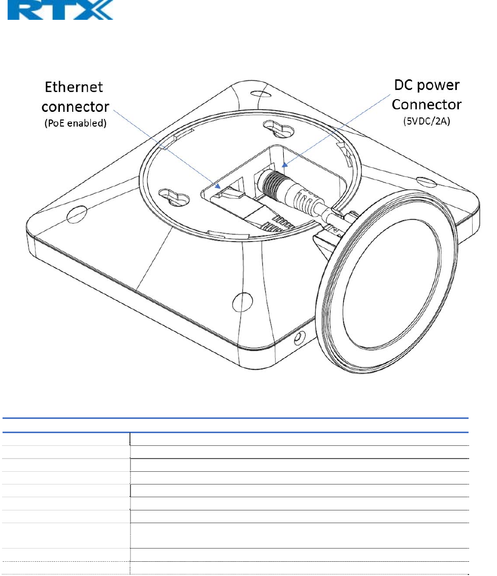
Itispossibletorestartorresetthebasestationunitbypressingaknobattherearsideoftheunit.Alternatively,itcan
beresetfromtheSMEConfigurationInterface.Wedonotrecommendthis;butunpluggingandpluggingtheEthernet
cablebacktothePoEportofthebasestationalsoresetsthebaseunit.
DBS‐210‐3PC‐NA‐K9TYPEAPPROVALUSERGUIDE1.0
11|Page
ProprietaryandConfidential
3.4 FindIPofBaseStation
TofindIPoftheinstalledbasestationtwomethodscanbeused;UsinghandsetFindIPfeatureorbrowserIPDECT
feature.
3.4.1 UsinghandsetFindIPfeature
Onthehandsetpress“Menu”keyfollowedbythekeys:*47*togetthehandsetintofindbasesmenu.Thehandset
willnowscanfor8660bases.Dependingontheamountofpoweredonbaseswithactiveradiosandthedistanceto
thebaseitcantakeuptominutestofindabase.
‐Usethecursordown/uptoselectthebaseMACaddressforthebase
‐ThebaseIPaddresswillbeshowninthedisplay
Thefeatureisalsousedfordeployment.
3.4.2 UsingbrowserIPDECT
Openanystandardbrowserandentertheaddress:
http://ipdect<MAC‐Address‐Base‐Station>
fore.g.http://ipdect00087B00AA10.ThiswillretrievetheHTTPWebServerpagefromthebasestationwithhardware
address00087B00AA10.
ThisfeaturerequiresanavailableDNSserver.
3.5 LogintoBaseSMEConfigurationInterface
1.ConnecttheBasestationtoaprivatenetworkviastandardEthernetcable(CAT‐5).
2.UsetheIPfindmenuinthehandset(Menu*47*)todeterminetheIP‐addressofthebasestationbymatchingthe
MACaddressonthebackofthebasestationwiththeMACaddresslistinthehandset.
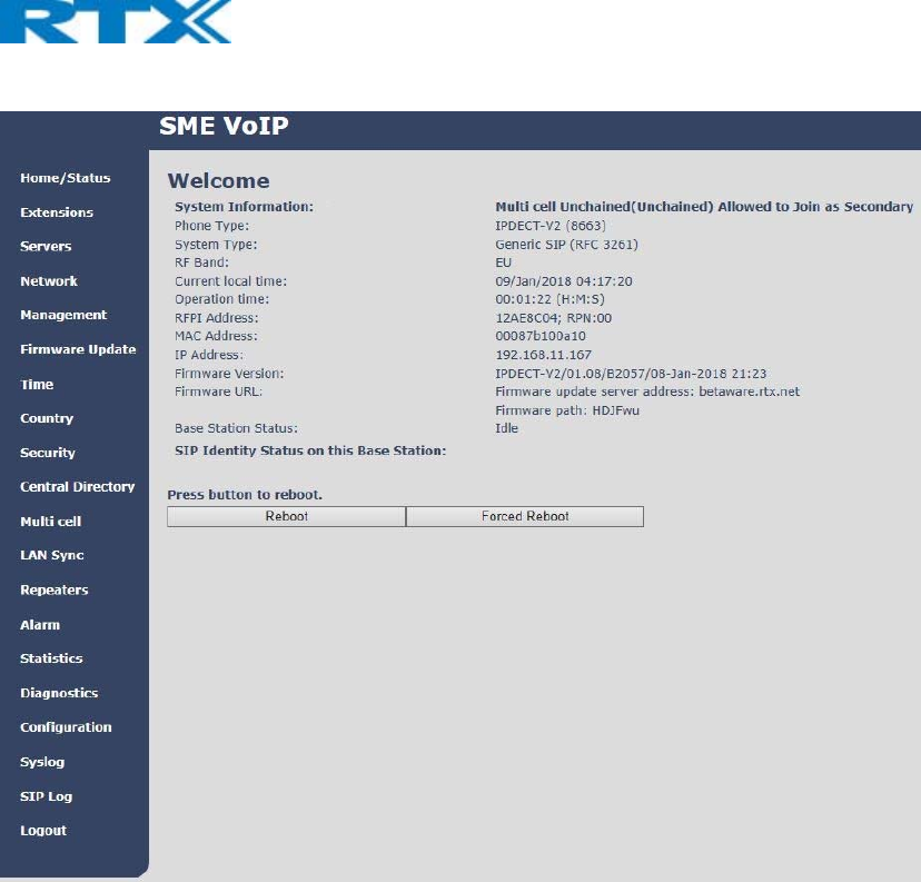
3.OntheLoginpage,enteryourauthenticatingcredentials(i.e.usernameandpassword).Bydefault,theusername
andpasswordareadmin.ClickOKbutton.
4.Onceyouhaveauthenticated,thebrowserwilldisplayfrontendoftheSMEConfigurationInterface.Thefrontend
willshowrelevantinformationofthebasestation.
Screenshot:
DBS‐210‐3PC‐NA‐K9TYPEAPPROVALUSERGUIDE1.0
12|Page
ProprietaryandConfidential
4 MakingHandsetReady
Inthischapter,webrieflydescribehowtopreparethehandsetforuse,install,insertandchargenewbatteries.Please
refertoanaccompanyingHandsetUserGuideformoreinformationofthefeaturesavailableintheHandset.
4.1 Package–Contents/DamageInspection
BeforePackageIsOpened:
Examinetheshippingpackageforevidenceofphysicaldamageormishandlingpriortoopening.Ifthereisaproofof
mishandlingpriortoopening,youmustreportittotherelevantsupportcenteroftheregionalrepresentativeor
operator.
ContentsofPackage:
Makesureallrelevantcomponentsareavailableinthepackagebeforeproceedingtothenextstep.
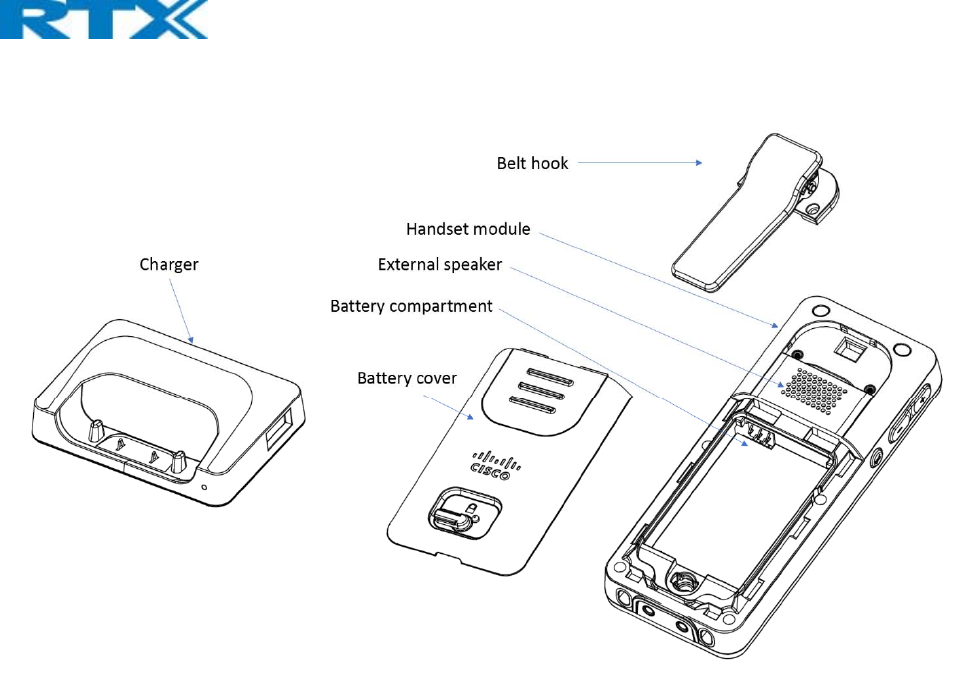
Everyshippedbaseunitpackage/boxcontainsthefollowingitems:
1xHandsethook
1xA/CAdaptor
1xBattery
1xcharger
1xHandsetUnit
1xBatterycover,
1xBelthook
DBS‐210‐3PC‐NA‐K9TYPEAPPROVALUSERGUIDE1.0
13|Page
ProprietaryandConfidential
DamageInspection:
Thefollowingaretherecommendedprocedureforyoutouseforinspection:
1. Examineallrelevantcomponentsfordamage.
2. Makea“defectiveonarrival–DOA”reportorRMAtotheoperator.Donotmovetheshippingcartonuntil
theoperatorhasexaminedit.Theoperator/regionalrepresentativewillinitiatethenecessaryprocedureto
processthisRMA.Theywillguidethenetworkadministratoronhowtoreturnthedamagedpackageif
necessary.
3. Ifnodamageisfound,thenunwrapallthecomponentsanddisposeofemptypackage/carton(s)in
accordancewithcountryspecificenvironmentalregulations.
4.2 BeforeUsingthePhone
Herearethepre‐cautionsusersshouldreadbeforeusingtheHandset:
InstallingtheBattery
1. Neverdisposebatteryinfires,otherwiseitwillexplode.
2. Neverreplacethebatteriesinpotentiallyexplosiveenvironments,e.g.closetoinflammableliquids/gases.
3. ONLYuseapprovedbatteriesandchargersfromthevendororoperator.
4. Donotdisassemble,customize,orshortcircuitthebattery
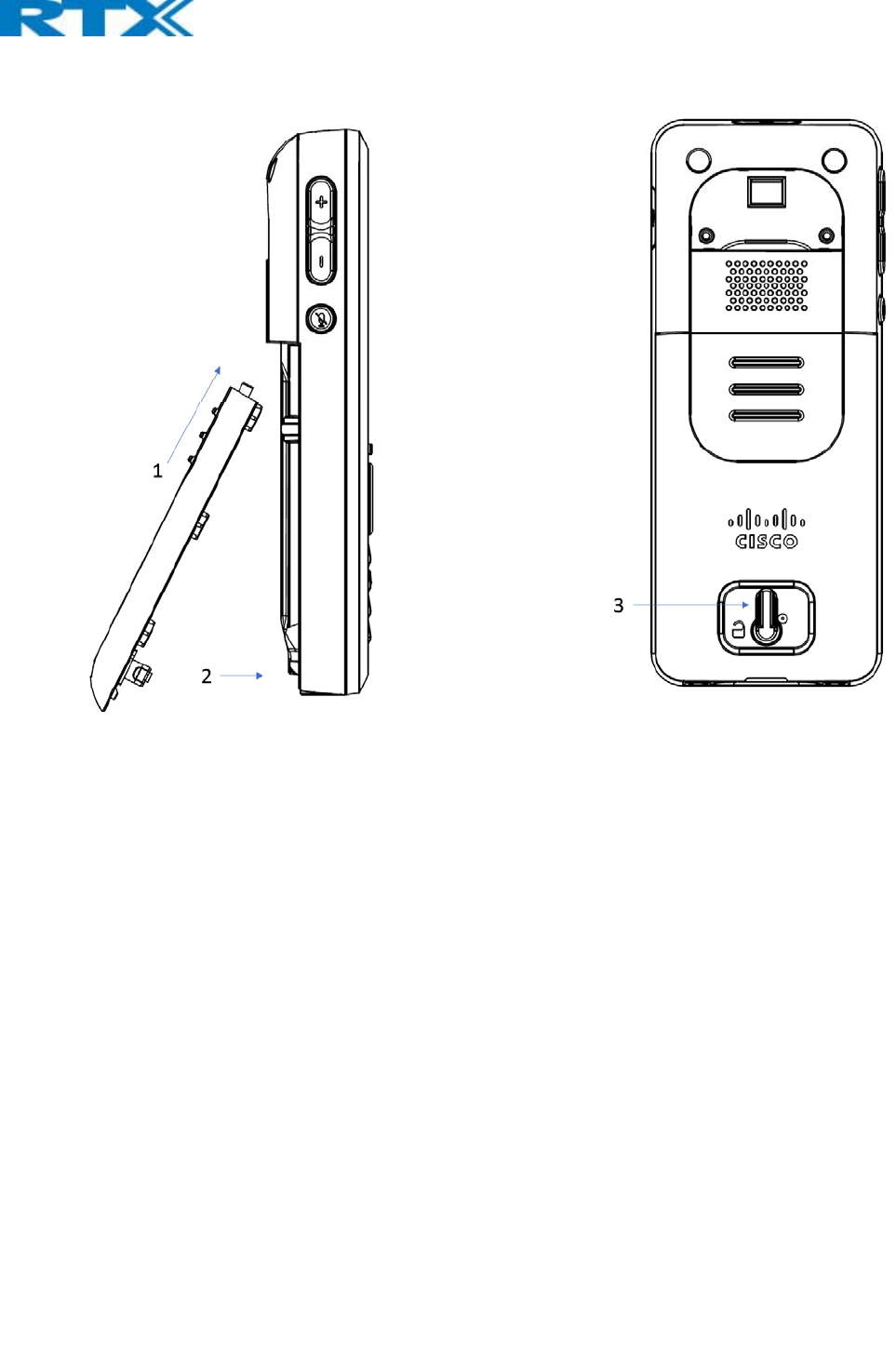
ClosingBackCover
1. Slidethetopofthebatterycoverintothedesignatedslotofthehandset(seestep1inbelowdrawing)
2. Pressthebottomofthebatterycoverontothehandset(seestep2inbelowdrawing)
3. Movethelockpinto“lockedposition”(seestep3inbelowdrawing)
ReplaceBattery
RemoveBackCoverfromHandset.Removetheoldbatteryandreplacewithanewone.
DBS‐210‐3PC‐NA‐K9TYPEAPPROVALUSERGUIDE1.0
14|Page
ProprietaryandConfidential
UsingtheCharger
Eachhandsetischargedusingahandsetcharger.Thechargerisacompactdesktopunitdesignedtochargeand
automaticallymaintainthecorrectbatterychargelevelsandvoltage.
ThechargerHandsetispoweredbyACsupplyfrom110‐240VACthatsupplies5.0VDCat2A.
Whenchargingthebatteryforthefirsttime,itisnecessarytoleavethehandsetinthechargerforatleast10hours
beforethebatteryisfullychargedandthehandsetreadyforuse.
HandsetintheCharger
Forcorrectcharging,ensurethattheroomtemperatureisbetween5°Cand25°C/41°Fand77°F.Donotplacethe
handsetindirectsunlight.Thebatteryhasabuilt‐inheatsensorwhichwillstopchargingifthebatterytemperatureis
toohigh.
Ifthehandsetisturnedoffwhenplacedincharger,onlytheLEDindicatesthecharging.Whenhandsetisturnedoff,
theLEDflashesatalowfrequencywhilechargingandlightsconstantlywhenthechargingisfinished.Therewillbe
responseforincomingcalls.
Ifthehandsetisturnedonwhencharging,thedisplayshowsthechargingstatus.
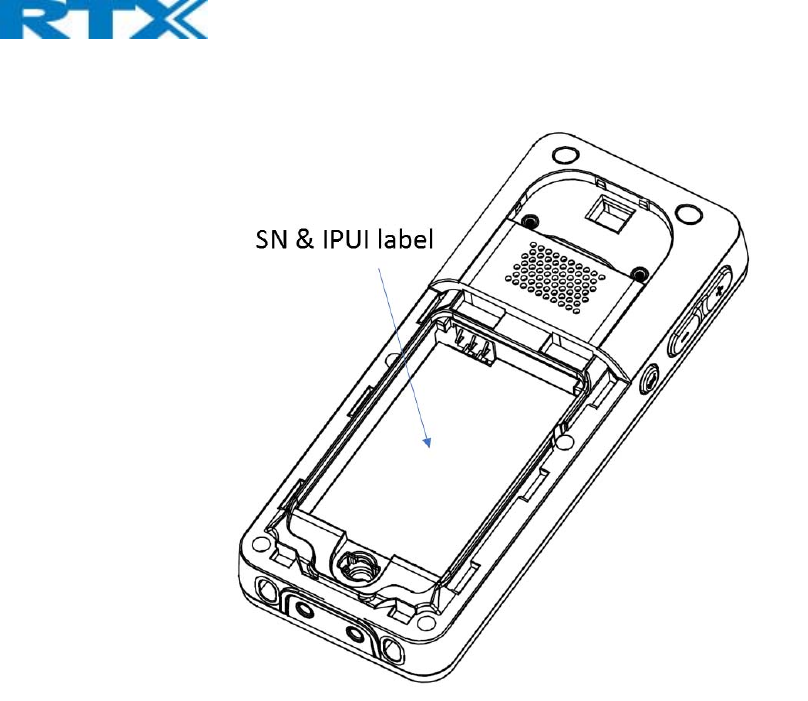
HandsetSerialNumber
Theserialnumber(IPEI/IPUInumber)ofeachhandsetisfoundeitheronalabel,whichisplacedbehindthebattery,or
onthepackaginglabel.First,liftoffhandsetbackcoverandliftthebatteryandreadtheserialnumber.
Theserialnumberisneededtoenableservicetothehandset.Itmustbeprogrammedintothesystemdatabasevia
theSMEVoIPConfigurationinterface.
DBS‐210‐3PC‐NA‐K9TYPEAPPROVALUSERGUIDE1.0
15|Page
ProprietaryandConfidential

FCC Warning:
This device complies with part 15 of the FCC Rules. Operation is subject to the following two conditions:
(1) This device may not cause harmful interference, and (2) this device must accept any interference
received, including interference that may cause undesired operation. Any Changes or modifications not
expressly approved by the party responsible for compliance could void the user's authority to operate the
equipment.
Note: This equipment has been tested and found to comply with the limits for a Class B digital device,
pursuant to part 15 of the FCC Rules. These limits are designed to provide reasonable protection against
harmful interference in a residential installation. This equipment generates, uses and can radiate radio
frequency energy and, if not installed and used in accordance with the instructions, may cause harmful
interference to radio communications. However, there is no guarantee that interference will not occur in a
particular installation. If this equipment does cause harmful interference to radio or television reception,
which can be determined by turning the equipment off and on, the user is encouraged to try to correct the
interference by one or more of the following measures:
—Reorient or relocate the receiving antenna.
—Increase the separation between the equipment and receiver.
—Connect the equipment into an outlet on a circuit different from that to which the receiver is connected.
—Consult the dealer or an experienced radio/TV technician for help.
FCC Exposure to Radio Frequency (RF) Signals
For Handset
This is a radio transmitter and receiver. It is designed and manufactured not to exceed the emission limitsfor
exposure to radio frequency (RF) energy set by the Federal Communications Commission (FCC) of the
U.S.Government. These limits are part of comprehensive guidelines and establish permitted levels of RF
energy for the general population. The guidelines are based on the safety standards previously set by both
U.S. and international standards bodies. These standards include a substantial safety margin designed to
assure the safety of all persons,regardless of age and health. This device and its antenna must not be co-
located or operating in conjunction with any other antenna or transmitter. This product has been shown to be
capable of compliance for localized specific absorption rate (SAR) for uncontrolled environment/general
population exposure limits specified in ANSI/IEEE Std. C95.1-1992 and had been tested in accordance with
the measurement procedures specified in FCC/OET Bulletin 65 Supplement C (2001) and IEEE 1528.
For Base
This equipment complies with FCC radiation exposure limits set forth for an uncontrolled environment. This
equipment should be installed and operated with minimum distance 20cm between the radiator& your body.
This transmitter must not be co-located or operating in conjunction with any other antenna or transmitter.
ISEDC Warning:
This device complies with ISEDC licence-exempt RSS standard(s). Operation is subject to the following two
conditions:
(1) this device may not cause interference, and
(2) this device must accept any interference, including interference that may cause undesired operation of
the device.
Le présent appareil est conforme aux CNR d'ISEDC applicables aux appareils radio exempts de
licence.L'exploitation est autorisée aux deux conditions suivantes :

(1) l'appareil nedoit pas produire de brouillage, et
(2) l'utilisateur de l'appareil doit accepter tout brouillage radioélectrique subi, même si le brouillage est
susceptible d'en compromettre le fonctionnement.
ISEDC Specific Absorption Rate (SAR) information
For Handset
SAR tests are conducted using standard operating positions accepted by the ISEDC with device transmitting
at its highest certified power level in all tested frequency bands, although the SAR is determined at the
highest certified power level, the actual SAR level of the device while operating can be well below the
maximum value. Before a new model device is a available for sale to the public, it must be tested and
certified to the ISEDC that it does not exceed the exposure limit established by the ISEDC, tests for each
device are performed in positions and locations as required by the ISEDC. For body worn operation, this
model device has been tested and meets the ISEDC RF exposure guidelines when used with an accessory
designated for this product or when used with an accessory that contains no metal.
For Base
This equipment complies with ISEDC radiation exposure limits set forth for an uncontrolled environment. This
equipment should be installed and operated with minimum distance 20cm between the radiator& your body.
This transmitter must not be co-located or operating in conjunction with any other antenna or transmitter.
ISEDC Radiation Exposure Statement:
For Handset
SAR l’utilisation des règles sma l’emplacement Le matériel de transmission et fonctionnant dans tous les
essais à la certification, même si la puissance suprême a décidé le niveau, utilisation spécifique peut être
très en deçà de la valeur de référence maximale.Types de matériel sont vendus au public un ancien, d’essai
et de certification de l’exposition, limite maximum sma, chaque document et l’emplacement du matériel
d’essai et conformément au document.Le modèle en physique, matériel d’essai et conforme aux directives
d’exposition des radiofréquences sma quand une annexe désigné pour ce produit lors de leur utilisation ou
des pièces de rechange ne contiennent pas de métal.
For Base
Cet équipement est conforme aux limites d'exposition aux radiations ISEDC définies pour un environnement non
contrôlé. Cet équipement doit être installé et utilisé avec une distance minimale de 20 cm entre le radiateur et votre
corps.
Cet émetteur ne doit pas être situé ou fonctionner conjointement avec une autre antenne ou un autre émetteur.