RYOBI Jointer/Planer Manual L0908693
User Manual: RYOBI RYOBI Jointer/Planer Manual RYOBI Jointer/Planer Owner's Manual, RYOBI Jointer/Planer installation guides
Open the PDF directly: View PDF ![]() .
.
Page Count: 22

OPERATO
LATE JOI
_1-1
DOUBLE iNSULATED
UAL
Your new tool has been engineered and manufactured to Ryobi's high standard for dependability, ease of operation, and
operator safety. When properly cared for, it will give you years of rugged, trouble-free performance.
[,_ wARN_NG:T_reduc_t_ri_k_fi_jury_th_us_rmustreada_du_d_rsta_dth_p_rat_r_sma_ualb_f_reusi_g ]thisproduct. _
Thank you for buying a Ryobi Product.
[] Introduction.....................................................................................................................................................................2
[] GeneralSafetyRules..................................................................................................................................................3-4
[] SpecificSafetyRules......................................................................................................................................................4
[] Symbols...........................................................................................................................................................................5
[] Electrical..........................................................................................................................................................................6
[] Features......................................................................................................................................................................7-8
[] Adjustments..............................................................................................................................................................9-10
[] Operation.................................................................................................................................................................11-16
[] Maintenance............................................................................................................................................................17-19
[] Accessories...................................................................................................................................................................19
[] Troubleshooting............................................................................................................................................................20
[] Serviceinformation.......................................................................................................................................................22
Spiinejoineryis oneof thestrongestmethodsofjoineryusedinwoodworking.Whenglueisproperlyappliedto aspline
andto thejointareaof thewoodpiecesbeingconnected,a largesurfaceareareceivestheadhesionpropertiesofthe
glue.Thisformsaverystrongjoint.
Traditionalspiinejoineryrequirescuttingslotswitha routerortablesaw.Small,thinstripsofwoodmustthenbecuttofit
insidetheslotsandactassplines.
Newermethodsofsplinejoineryuseaplateorbiscuitjoinertocutprecisematingovalslotsinadjoiningboards.Yournew
platejoinerisafast,simple,andaccurateplungecuttingtoolthatcanbeusedforthispurpose.Itcanbeusedtocutslots
inhardwood,softwood,plywood,particleboard,andotherpressedwoods.
Footballshapedwafers,calledbiscuits,arethenplacedinsidethe slotswithglueandusedto helplineupadjoining
surfaces.Whena waterbasedglueis used,the biscuitsswellinthejoint,makinganextremelystrongandfirmbond.
Whiteglue,yellowglue,carpentersglue,hideglue,andaiiphaticresinglueareexamplesof waterbasedglues.This
bondingtechniquehastraditionallybeenlimitedto makingedge-to-edgejoints.However,withtheuseofyournewplate
joiner,biscuitscannowbeeasilyusedtoconnectbutt,miter,andT-joints.Biscuitjoiningcanbeasstrongasmortiseand
tenon,tongueandgroove,standardspline,anddoweledjoints.Inmostcasesthematerialaroundthebiscuitwillbreak
beforethebiscuititselfwillbreak.A greatersurfaceareaisexposedtoglueina biscuitjoint,makingtheseamsstronger.
WARNING"
Do not attempt to use this tool until you have read
thoroughly and understand completely the
operator's manual. Pay close attention to the safety
rules, including Dangers, Warnings, and Cautions.
If you use this tool properly and only for what it is
intended, you will enjoy years of safe, reliable
service.
Look for this symbol to point out important safety precautions. It
means attention!!! Your safety is involved.
WARNING:
The operation of any tool can result in foreign objects being thrown into your eyes, which can
result in severe eye damage. Before beginning operation, always wear safety goggles or safety
glasses with side shields and a full face shield when needed. We recommend Wide Vision Safety
Mask for use over eyeglasses or standard safety glasses with side shields. Always wear eye
protection which is marked to comply with ANSI Z87.1.
Page 2

WARNING:
Read and understand all instructions. Failure to fol-
low all instructions listed below, may result in electric
shock, fire and/or serious personal injury.
SAVE THESE iNSTRUCTIONS
WORK AREA
[] Keep your work area clean and well lit. Cluttered
benches and dark areas invite accidents.
[] Do not operate power tools in explosive atmospheres,
such as in the presence of flammable liquids, gases,
or dust. Power tools create sparks which may ignite the
dust or fumes.
Keep bystanders, children, and visitors away while
operating a power tool. Distractions can cause you to
lose control.
ELECTRICAL SAFETY
[] Double insulated tools are equipped with a polarized
plug (one blade is wider than the other). This plug
will fit in apolarized outlet only one way. If the plug
does not fit fully in the outlet, reverse the plug. If it
still does not fit, contact a qualified electrician to in-
stall a polarized outlet. Do not change the plug in any
way. Double insulation [] eliminates the need for the
three-wire grounded power cord and grounded power
supply system.
[] Avoid body contact with grounded surfaces such as
pipes, radiators, ranges, and refrigerators. There is
an increased risk of electric shock ifyour body is grounded.
[] Don't expose power tools to rain or wet conditions.
Water entering a power tool will increase the risk of elec-
tric shock.
[] Do not abuse the cord. Never use the cord to carry
the tools or pull the plug from an outlet. Keep cord
away from heat, oil, sharp edges, or moving parts.
Replace damaged cords immediately. Damaged cords
increase the risk of electric shock.
When operating a power tool outside, use an outdoor
extension cord marked "W-A" or "W". These cords are
rated for outdoor use and reduce the risk of electric shock.
PERSONAL SAFETY
[] Stay alert, watch what you are doing and use com-
mon sense when operating a power tool. Do not use
tool while tired or under the influence of drugs, alco-
hol, or medication. A moment of inattention while oper-
ating power tools may result in serious personal injury.
[] Dress properly. Do not wear loose clothing or jew-
elry. Contain long hair. Keep your hair, clothing, and
gloves away from moving parts. Loose clothes, jew-
elry, or long hair can be caught in moving parts.
[] Avoid accidental starting. Be sure switch is off be-
fore plugging in. Carrying tools with your finger on the
switch or plugging in tools that have the switch on invites
accidents.
[] Remove adjusting keys or wrenches before turning
the tool on. A wrench or a key that is left attached to a
rotating part of the tool may result in personal injury.
[] Do not overreach. Keep proper footing and balance
at all times. Proper footing and balance enables better
control of the tool in unexpected situations.
[] Use safety equipment. Always wear eye protection.
Dust mask, nonskid safety shoes, hard hat, or hearing
protection must be used for appropriate conditions.
[] Do not wear loose clothing or jewelry. Contain long
hair. Loose clothes, jewelry, or long hair can be drawn
into air vents.
[] Do not use on a ladder or unstable support. Stable
footing on a solid surface enables better control of the
tool in unexpected situations.
TOOL USE AND CARE
[] Use clamps or other practical way to secure and sup-
port the workpiece to a stable platform. Holding the
work by hand or against your body is unstable and may
lead to loss of control.
[] Do not force tool. Use the correct tool for your appli-
cation. The correct tool will do the job better and safer at
the rate for which it is designed.
[] Do not use tool if switch does not turn it on or off.
Any tool that cannot be controlled with the switch is dan-
gerous and must be repaired.
[] Disconnect the plug from power source before mak-
ing any adjustments, changing accessories, or stor-
ing the tool. Such preventive safety measures reduce
the risk of starting the tool accidentally.
[] Store idle tools out of the reach of children and other
untrained persons. Tools are dangerous in the hands of
untrained users.
[] Maintain tools with care. Keep cutting tools sharp and
clean. Properly maintained tools with sharp cutting edges
are less likely to bind and are easier to control.
[] Check for misalignment or binding of moving parts,
breakage of parts, and any other condition that may
affect the tool's operation. If damaged, have the tool
serviced before using. Many accidents are caused by
poorly maintained tools.
[] Use only accessories that are recommended by the
manufacturer for your model. Accessories that may be
suitable for one tool, may become hazardous when used
on another tool.
[] Keep the tool and its handle dry, clean and free from
oil and grease. Always use a clean cloth when cleaning.
Never use brake fluids, gasoline, petroleum-based prod-
ucts, or any strong solvents to clean your tool. Following
this rule will reduce the risk of loss of control and deterio-
ration of the enclosure plastic.
Page 3

SERVICE []
[] Tool service must be performed only by qualified re-
pair personnel. Service or maintenance performed by
unqualified personnel may result in a risk of injury.
When servicing a tool, use only identical replacement
parts. Follow instructions in the Maintenance section
of this manual. Use of unauthorized parts or failure to
follow Maintenance Instructions may create a risk of shock
or injury.
[] Hold tool by insulated gripping surfaces when per-
forming an operation where the cutting tool may
contact hidden wiring or its own cord. Contact with a
"live" wire will make exposed metal parts of the cutting
tool "live" and shock the operator.
ADDITIONAL SAFETY RULES
[] Know your power tool. Read operator's manual care-
fully. Learn its applications and limitations, as well
as the specific potential hazards related to this tool.
Following this rule will reduce the risk of electric shock,
fire, or serious injury.
[] Always wear safety glasses. Everyday eyeglasses
have only impact-resistant lenses; they are NOT
safety glasses. Following this rule will reduce the risk of
serious personal injury.
[] Protect your lungs. Wear a face or dust mask if the
operation is dusty. Following this rule will reduce the
risk of serious personal injury.
[] Protect your hearing. Wear hearing protection dur-
ing extended periods of operation. Following this rule
will reduce the risk of serious personal injury.
[] Inspect tool cords periodically and, if damaged, have
repaired at your nearest Authorized Service Center.
Constantly stay aware of cord location. Following this
rule will reduce the risk of electric shock or fire.
[] Check damaged parts. Before further use of the tool,
a guard or other part that is damaged should be care=
fully checked to determine that it will operate prop-
erly and perform its intended function. Check for
alignment of moving parts, binding of moving parts,
breakage of parts, mounting, and any other condi-
tions that may affect its operation. Aguard or other
part that is damaged should be properly repaired or
replaced by an authorized service center. Following
this rule will reduce the risk of shock, fire, or serious in-
jury.
[] Do not abuse cord. Never carry the tool by the cord
or yank it to disconnect it from the receptacle. Keep
cord away from heat, oil, and sharp edges. Following
this rule will reduce the risk of electric shock or fire.
[] Make sure your extension cord is in good condition.
When using an extension cord, be sure to use one
heavy enough to carry the current your product will
draw. A wire gage size (A.W.G.) of at least 14 is rec-
ommended for an extension cord 50 feet or less in
length. A cord exceeding 100 feet is not recom-
mended. If in doubt, use the next heavier gage. The
smaller the gage number, the heavier the cord. An un-
dersized cord will cause a drop in line voltage resulting in
loss of power and overheating.
[] Inspect for and remove all nails from lumber before
using this tool. Following this rule will reduce the risk of
serious personal injury.
[] Drugs, alcohol, medication. Do not operate tool while
under the influence of drugs, alcohol, or any medica-
tion. Following this rule will reduce the risk of electric
shock, fire, or serious personal injury.
[] Save these instructions. Refer to them frequently and
use them to instruct others who may use this tool. If you
loan someone this tool, loan them these instructions also.
WARNING:
Some dust created by power sanding, sawing, grinding,
drilling, and other construction activities contains chemi-
cals known to cause cancer, birth defects or other repro-
ductive harm. Some examples of these chemicals are:
• lead from lead-based paints,
• crystalline silica from bricks and cement and
other masonry products, and
• arsenic and chromium from chemically-treated
lumber.
Your risk from these exposures varies, depending on
how often you do this type of work. To reduce your
exposure to these chemicals: work in a well ventilated
area, and work with approved safety equipment, such as
those dust masks that are specially designed to filter out
microscopic particles.
SAVE THESE INSTRUCTIONS
Page 4
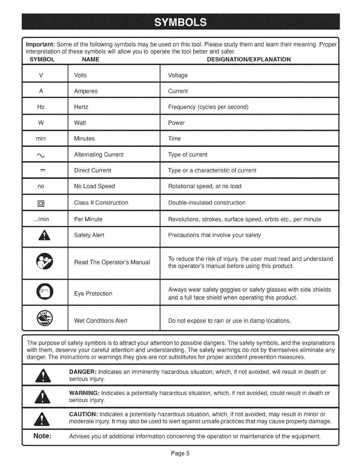
Important:Someofthefollowingsymbolsmaybeusedonthistool.Pleasestudythemandlearntheirmeaning.Proper
interpretationofthesesymbolswillallowyoutooperatethetoolbetterandsafer.
SYMBOL
V
A
Hz
W
min
no
[]
.../min
A
0
@
NAME
Volts
Amperes
Hertz
Watt
Minutes
Alternating Current
Direct Current
No Load Speed
Class II Construction
Per Minute
Safety Alert
Read The Operator's Manual
Eye Protection
Wet Conditions Alert
DESIGNATION/EXPLANATION
Voltage
Current
Frequency (cycles per second)
Power
Time
Type of current
Type or a characteristic of current
Rotational speed, at no load
Double-insulated construction
Revolutions, strokes, surface speed, orbits etc., per minute
Precautions that involve your safety
To reduce the risk of injury, the user must read and understand
the operator's manual before using this product.
Always wear safety goggles or safety glasses with side shields
and a full face shield when operating this product.
Do not expose to rain or use in damp locations.
The purpose of safety symbols is to attract your attention to possible dangers. The safety symbols, and the explanations
with them, deserve your careful attention and understanding. The safety warnings do not by themselves eliminate any
danger. The instructions or warnings they give are not substitutes for proper accident prevention measures.
,&
,&
Note:
DANGER: Indicates an imminently hazardous situation, which, if not avoided, will result in death or
serious injury.
WARNING: Indicates a potentially hazardous situation, which, if not avoided, could result in death or
serious injury.
CAUTION: Indicates a potentially hazardous situation, which, if not avoided, may result in minor or
moderate injury. It may also be used to alert against unsafe practices that may cause property damage.
Advises you of additional information concerning the operation or maintenance of the equipment.
................................................................................................................
Page 5
DOUBLE INSULATION
Your Ryobi power tool is double insulated. This means you
are separated from the tool's electrical system by two complete
sets of electrical insulation. This extra layer of insulation is
intended to protect the user from electrical shock due to a
break in the wiring insulation. All exposed metal parts are
isolated from the internal metal motor components with
protecting insulation. Double insulated tools do not need to
be grounded.
Important: Servicing of a tool with double
insulation requires extreme care and knowledge
of the system and should be performed only by
a qualified technician. For service, we suggest
you return the tool to your nearest authorized
service center for repair. When servicing, use
original factory replacement parts.
WARNING:
The double insulated system is intended to protect the
user from shock resulting from a break in the tool's
internal wiring. Observe all normal safety precautions
related to avoiding electrical shock.
ELECTRICAL CONNECTION
This tool has a precision-built electric motor. It should be
connected to a power supply that is 120 volts, 60 HZ, AC only
(normal household current). Do not operate this tool on direct
current (DC). A substantial voltage drop will cause a loss of
power and the motor will overheat. If our tool does not
operate when plugged into an outlet, double-check the
power supply.
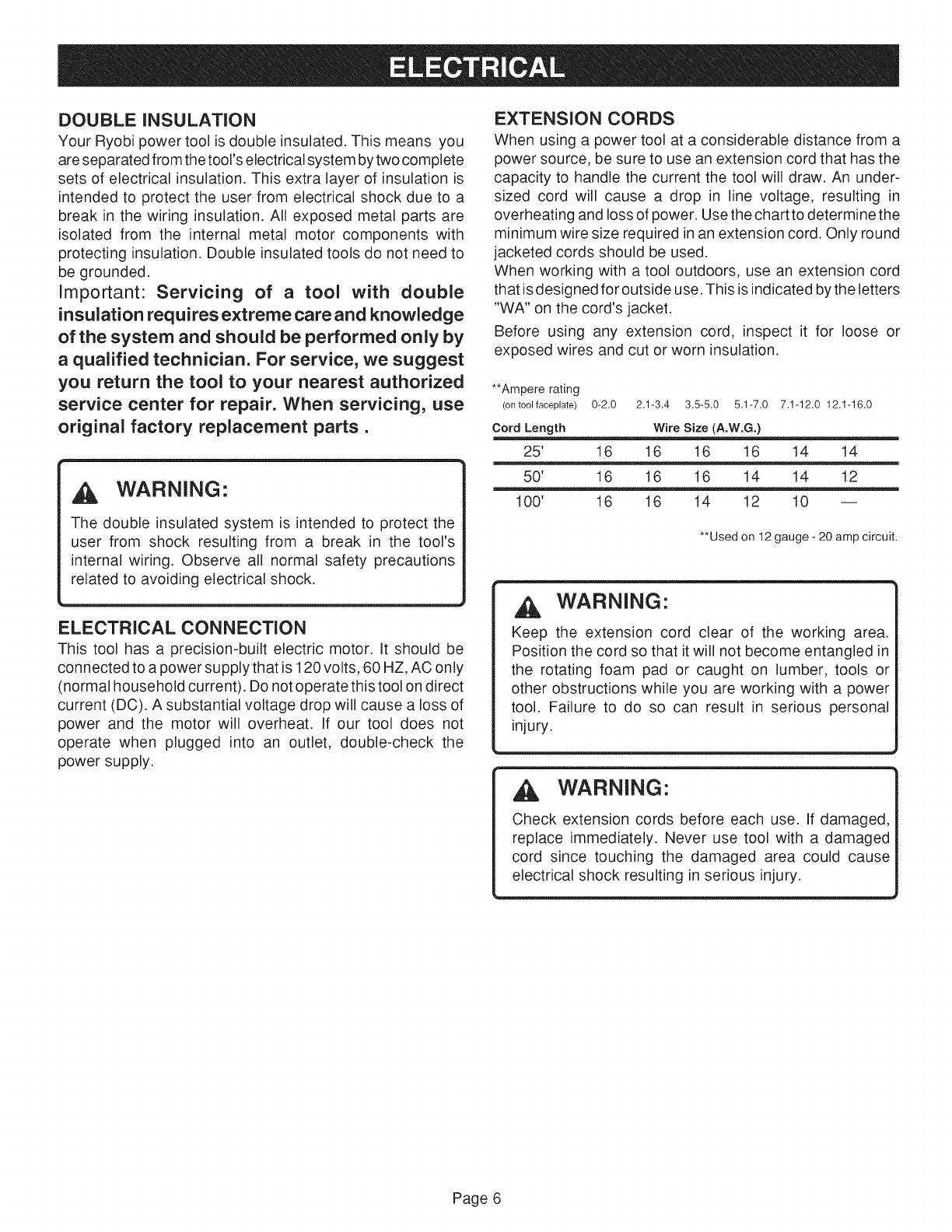
EXTENSION CORDS
When using a power tool at a considerable distance from a
power source, be sure to use an extension cord that has the
capacity to handle the current the tool will draw. An under-
sized cord will cause a drop in line voltage, resulting in
overheating and loss of power. Use the chart to determi ne the
minimum wire size required in an extension cord. Only round
jacketed cords should be used.
When working with a tool outdoors, use an extension cord
that is designed for outside use. This is indicated by the letters
"WA" on the cord's jacket.
Before using any extension cord, inspect it for loose or
exposed wires and cut or worn insulation.
**Ampere rating
(ontool faceplate) 0-2.0 2.1-3.4 3.5-5.0 5.1-7.0 7.1-12.0 12.1-16.0
Cord Length Wire Size (A.W.G.)
25' 16 16 16 16 14 14
50' 16 16 16 14 14 12
100' 16 16 14 12 10 --
**Used on 12 gauge - 20 amp circuit.
WARNING"
Keep the extension cord clear of the working area.
Position the cord so that it will not become entangled in
the rotating foam pad or caught on lumber, tools or
other obstructions while you are working with a power
tool. Failure to do so can result in serious personal
injury.
,_, WARNING"
Check extension cords before each use. If damaged,
replace immediately. Never use tool with a damaged
cord since touching the damaged area could cause
electrical shock resulting in serious injury.
Page 6
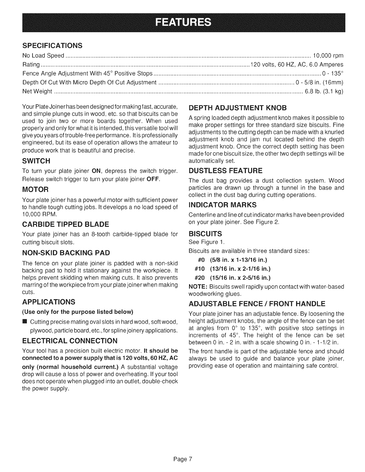
SPECIFICATIONS
No Load Speed .................................................................................................................................................... 10,000 rpm
Rating .............................................................................................................................. 120 volts, 60 HZ, AC, 6.0 Amperes
Fence Angle Adjustment With 45 ° Positive Stops ..................................................................................................... 0 - 135°
Depth Of Cut With Micro Depth Of Cut Adjustment .................................................................................. 0 - 5/8 in. (16mm)
Net Weight ...................................................................................................................................................... 6.8 lb. (3.1 kg)
Your Plate Joiner has been designed for making fast, accurate,
and simple plunge cuts in wood, etc. so that biscuits can be
used to join two or more boards together. When used
properly and only for what it is intended, this versatile tool will
give you years of trouble-free performance. It isprofessionally
engineered, but its ease of operation allows the amateur to
produce work that is beautiful and precise.
SWITCH
To turn your plate joiner ON, depress the switch trigger.
Release switch trigger to turn your plate joiner OFF.
MOTOR
Your plate joiner has a powerful motor with sufficient power
to handle tough cutting jobs. It develops a no load speed of
10,000 RPM.
CARBIDE TIPPED BLADE
Your plate joiner has an 8-tooth carbide-tipped blade for
cutting biscuit slots.
NON-SKID BACKING PAD
The fence on your plate joiner is padded with a non-skid
backing pad to hold it stationary against the workpiece. It
helps prevent skidding when making cuts. It also prevents
marring of the workpiece from your plate joinerwhen making
cuts.
APPLICATIONS
(Use only for the purpose listed below)
m Cutting precise mating oval slots in hard wood, soft wood,
plywood, particle board, etc., for spline joinery applications.
ELECTRICAL CONNECTION
Your tool has a precision built electric motor. It should be
connected to a power supply that is 120 volts, 60 HZ, AC
only (normal household current.) A substantial voltage
drop will cause a loss of power and overheating. If your tool
does not operate when plugged into an outlet, double-check
the power supply.
DEPTH ADJUSTMENT KNOB
A spring loaded depth adjustment knob makes it possible to
make proper settings for three standard size biscuits. Fine
adjustments to the cutting depth can be made with a knurled
adjustment knob and jam nut located behind the depth
adjustment knob. Once the correct depth setting has been
made for one biscuit size, the other two depth settings will be
automatically set.
DUSTLESS FEATURE
The dust bag provides a dust collection system. Wood
particles are drawn up through a tunnel in the base and
collect in the dust bag during cutting operations.
INDICATOR MARKS
Centerline and line of cut indicator marks have been provided
on your plate joiner. See Figure 2.
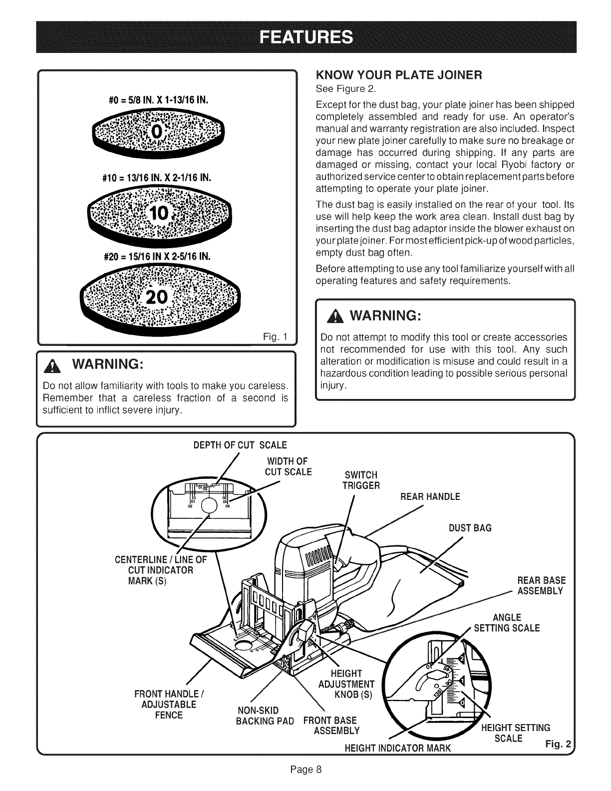
BISCUITS
See Figure 1.
Biscuits are available in three standard sizes:
#0 (5/8 in. x 1-13/16 in.)
#10 (13/16 in. x 2-1/16 in.)
#20 (15/16 in. x 2-5/16 in.)
NOTE: Biscuits swell rapidly upon contact with water-based
woodworking glues.
ADJUSTABLE FENCE /FRONT HANDLE
Your plate joiner has an adjustable fence. By loosening the
height adjustment knobs, the angle of the fence can be set
at angles from 0 ° to 135 ° , with positive stop settings in
increments of 45° . The height of the fence can be set
between 0 in. - 2 in. with a scale showing 0 in. - 1-1/2 in.
The front handle is part of the adjustable fence and should
always be used to guide and balance your plate joiner,
providing ease of operation and maintaining safe control.
Page 7
#0 = 5/8 IN, X 1-13/16 IN.
#10 = 13/16 IN. X 2-1/16 IN.
#20 = 15/16 IN X 2-5/16 IN.
Fig. 1
WARNING"
Do not allow familiarity with tools to make you careless.
Remember that a careless fraction of a second is
sufficient to inflict severe injury.
DEPTHOF CUT SCALE
WIDTHOF
CUTSCALE
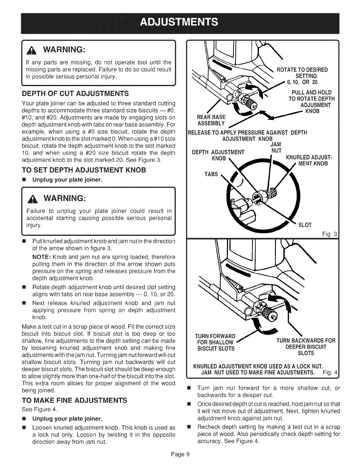
KNOW YOUR PLATE JOINER
See Figure 2.
Except for the dust bag, your plate joiner has been shipped
completely assembled and ready for use. An operator's
manual and warranty registration are also included. Inspect
your new plate joiner carefully to make sure no breakage or
damage has occurred during shipping. If any parts are
damaged or missing, contact your local Ryobi factory or
authorized service center to obtain replacement parts before
attempting to operate your plate joiner.
The dust bag is easily installed on the rear of your tool. Its
use will help keep the work area clean. Install dust bag by
inserting the dust bag adaptor inside the blower exhaust on
your plate joiner. For most efficient pick-up of wood particles,
empty dust bag often.
Before attempting to use any tool familiarize yourself with all
operating features and safety requirements.
WARNING:
Do not attempt to modify this tool or create accessories
not recommended for use with this tool. Any such
alteration or modification is misuse and could result in a
hazardous condition leading to possible serious personal
injury.
SWITCH
TRIGGER
REAR HANDLE
DUSTBAG
CENTERLINE/LINEOF
CUTiNDICATOR
MARK(S)
REARBASE
ASSEMBLY
ANGLE
SETTINGSCALE
FRONTHANDLE/
ADJUSTABLE
FENCE
HEIGHT
ADJUSTMENT
KNOB(S)
NON-SKID
BACKINGPAD FRONTBASE
ASSEMBLY HEIGHTSETTING
SCALE
HEIGHTINDICATORMARK Fig. 2
Page 8
WARNING:
If any parts are missing, do not operate tool until the
missing parts are replaced. Failure to do so could result
in possible serious personal injury.
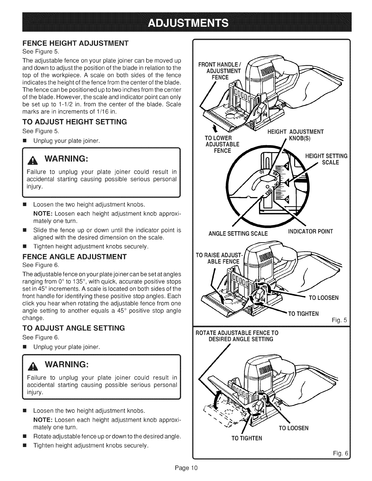
DEPTH OF CUT ADJUSTMENTS
Your plate joiner can be adjusted to three standard cutting
depths to accommodate three standard size biscuits -- #0,
#10, and #20. Adjustments are made by engaging slots on
depth adjustment knob with tabs on rear base assembly. For
example, when using a #0 size biscuit, rotate the depth
adjustment knob to the slot marked 0. When using a#10 size
biscuit, rotate the depth adjustment knob to the slot marked
10, and when using a #20 size biscuit rotate the depth
adjustment knob to the slot marked 20. See Figure 3.
TO SET DEPTH ADJUSTMENT KNOB
[] Unplug your plate joiner.
WARNING:
Failure to unplug your plate joiner could result in
accidental starting causing possible serious personal
injury.
[] Pull knuded adjustment knob and jam nut in the direction
of the arrow shown in figure 3.
NOTE: Knob and jam nut are spring loaded, therefore
pulling them in the direction of the arrow shown puts
pressure on the spring and releases pressure from the
depth adjustment knob.
[] Rotate depth adjustment knob until desired slot setting
aligns with tabs on rear base assembly -- 0, 10, or 20.
[] Next release knurled adjustment knob and jam nut
applying pressure from spring on depth adjustment
knob.
Make a test cut in a scrap piece of wood. Fit the correct size
biscuit into biscuit slot. If biscuit slot is too deep or too
shallow, fine adjustments to the depth setting can be made
by loosening knurled adjustment knob and making fine
adjustments with the jam nut. Turning jam nut forward will cut
shallow biscuit slots. Turning jam nut backwards will cut
deeper biscuit slots. The biscuit slot should be deep enough
to allow slightly more than one-half of the biscuit into the slot.
This extra room allows for proper alignment of the wood
being joined.
TO MAKE FiNE ADJUSTMENTS
See Figure 4.
[] Unplug your plate joiner.
[] Loosen knurled adjustment knob. This knob is used as
a lock nut only. Loosen by twisting it in the opposite
direction away from jam nut.
TATETOOESRE0
____'- PULL AND HOLD
RELEASETO APPLYPRESSUREAGAINST DEPTH
ADJUSTMENT KNOB
JAM
DEPTH ADJUSTMENT NUT
KNOB KNURLEDADJUST-
MENTKNOB
TABS
:SLOT
Fig. 3
FORSHALLOW
BISCUITSLOTS
TURNBACKWARDSFOR
DEEPERBISCUIT
SLOTS
KNURLEDADJUSTMENTKNOB USEDAS A LOCKNUT.
JAM NUTUSEDTO MAKE FiNEADJUSTMENTS. Fig. 4
[] Turn jam nut forward for a more shallow cut, or
backwards for a deeper cut.
[] Once desired depth of cut is reached, hold jam nut so that
it will not move out of adjustment. Next, tighten knuded
adjustment knob against jam nut.
[] Recheck depth setting by making a test cut in a scrap
piece of wood. Also periodically check depth setting for
accuracy. See Figure 4.
Page 9
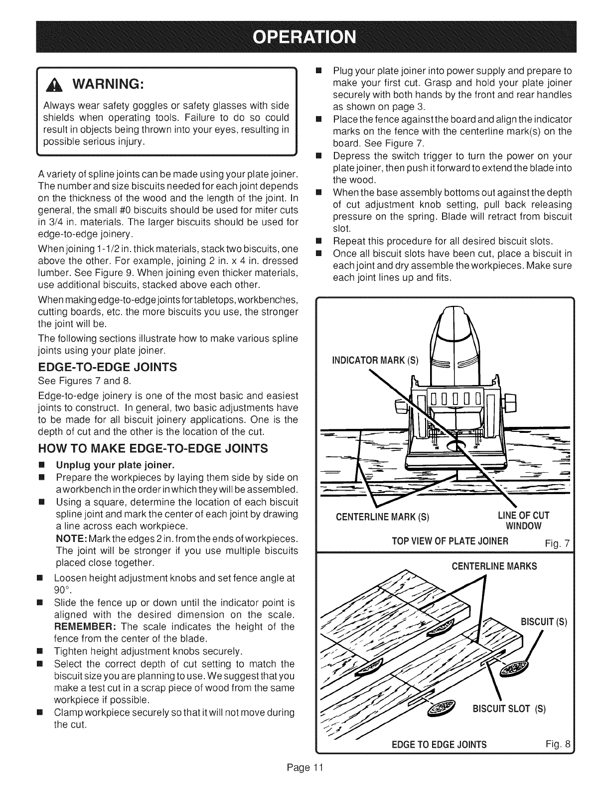
FENCE HEIGHT ADJUSTMENT
See Figure 5.
The adjustable fence on your plate joiner can be moved up
and down to adjust the position of the blade in relation to the
top of the workpiece. A scale on both sides of the fence
indicates the height of the fence from the center of the blade.
The fence can be positioned up to two inches from the center
of the blade. However, the scale and indicator point can only
be set up to 1-1/2 in. from the center of the blade. Scale
marks are in increments of 1/16 in.
TO ADJUST HEIGHT SETTING
See Figure 5.
[] Unplug your plate joiner.
WARNING:
Failure to unplug your plate joiner could result in
accidental starting causing possible serious personal
injury.
[] Loosen the two height adjustment knobs.
NOTE: Loosen each height adjustment knob approxi-
mately one turn.
[] Slide the fence up or down until the indicator point is
aligned with the desired dimension on the scale.
[] Tighten height adjustment knobs securely.
FENCE ANGLE ADJUSTMENT
See Figure 6.
The adjustable fence on your plate joiner can be set at angles
ranging from 0° to 135°, with quick, accurate positive stops
set in 45° increments. A scale is located on both sides of the
front handle for identifying these positive stop angles. Each
click you hear when rotating the adjustable fence from one
angle setting to another equals a 45 ° positive stop angle
change.
TO ADJUST ANGLE SETTING
See Figure 6.
[] Unp)ug your p)atejoiner.
WARNING"
Failure to unplug your plate joiner could result in
accidental starting causing possible serious personal
injury.
[] Loosen the two height adjustment knobs.
NOTE: Loosen each height adjustment knob approxi-
mately one turn.
[] Rotate adjustable fence up or down to the desired angle.
[] Tighten height adjustment knobs securely.
FRONTHANDLE/
ADJUSTMENT
FENCE
TO LOWER
ADJUSTABLE
FENCE
HEIGHTADJUSTMENT
KNOB(S)
HEIGHTSETTING
SCALE
ANGLE SETTINGSCALE INDICATORPOINT
TO RAISEADJUST-
ABLE FENCE
ROTATEADJUSTABLEFENCETO
DESIREDANGLE SETTING
TO LOOSEN
TOTIGHTEN
Fig. 5
TO TIGHTEN
TO LOOSEN
Fig. 6
Page10
WARNING:
Always wear safety goggles or safety glasses with side
shields when operating tools. Failure to do so could
result in objects being thrown into your eyes, resulting in
possible serious injury.
A variety of spline joints can be made using your plate joiner.
The number and size biscuits needed for each joint depends
on the thickness of the wood and the length of the joint. In
general, the small #0 biscuits should be used for miter cuts
in 3/4 in. materials. The larger biscuits should be used for
edge-to-edge joinery.
When joining 1-1/2 in. thick materials, stack two biscuits, one
above the other. For example, joining 2 in. x 4 in. dressed
lumber. See Figure 9. When joining even thicker materials,
use additional biscuits, stacked above each other.
When making edge-to-edge joints for tabletops, workbenches,
cutting boards, etc. the more biscuits you use, the stronger
the joint will be.
The following sections illustrate how to make various spline
joints using your plate joiner.
EDGE=TO-EDGE JOINTS
See Figures 7 and 8.
Edge-to-edge joinery is one of the most basic and easiest
joints to construct. In general, two basic adjustments have
to be made for all biscuit joinery applications. One is the
depth of cut and the other is the location of the cut.
HOW TO MAKE EDGE-TO-EDGE JOINTS
[] Unplug your plate joiner.
[] Prepare the workpieces by laying them side by side on
aworkbench inthe order inwhich they will be assembled.
[] Using a square, determine the location of each biscuit
spline joint and mark the center of each joint by drawing
a line across each workpiece.
NOTE: Markthe edges 2 in.from the ends of workpieces.
The joint will be stronger if you use multiple biscuits
placed close together.
[] Loosen height adjustment knobs and set fence angle at
90 °.
[] Slide the fence up or down until the indicator point is
aligned with the desired dimension on the scale.
REMEMBER: The scale indicates the height of the
fence from the center of the blade.
[] Tighten height adjustment knobs securely.
[] Select the correct depth of cut setting to match the
biscuit size you are planning to use. We suggest that you
make a test cut in a scrap piece of wood from the same
workpiece if possible.
[] Clamp workpiece securely so that it will not move during
the cut.
[] Plug your plate joiner into power supply and prepare to
make your first cut. Grasp and hold your plate joiner
securely with both hands by the front and rear handles
as shown on page 3.
[] Place the fence against the board and align the indicator
marks on the fence with the centerline mark(s) on the
board. See Figure 7.
[] Depress the switch trigger to turn the power on your
plate joiner, then push it forward to extend the blade into
the wood.
[] When the base assembly bottoms out against the depth
of cut adjustment knob setting, pull back releasing
pressure on the spring. Blade will retract from biscuit
slot.
[] Repeat this procedure for all desired biscuit slots.
[] Once all biscuit slots have been cut, place a biscuit in
each joint and dry assemble the workpieces. Make sure
each joint lines up and fits.
J
CENTERLINEMARK(S) LINEOF CUT
WINDOW
TOPVIEWOF PLATEJOINER Fig. 7
CENTERLINEMARKS
IT(S)
_ BISCUITSLOT (S)
EDGETO EDGEJOINTS Fig. 8
Page 11
[] Finally,disassembletheworkpiecesandplaceabeadof
glueineachslot.Also,spreada beadofglueoverthe
entiresurfaceof the joint.Reinsertthe biscuitsand
assembletheworkpieces.SeeFigure8.
[] Clampworkpiecestogetheruntilthegluesetsup.
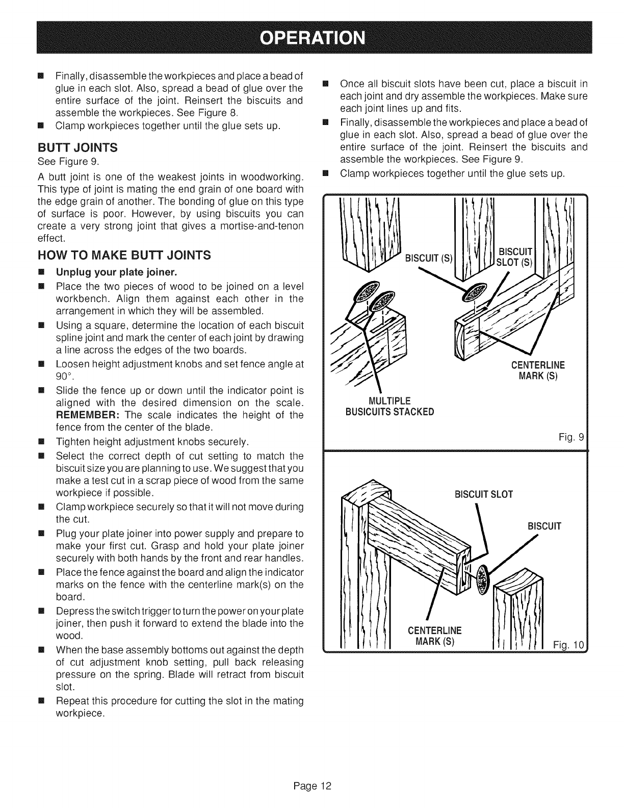
BUTT JOINTS
See Figure 9.
A butt joint is one of the weakest joints in woodworking.
This type of joint is mating the end grain of one board with
the edge grain of another. The bonding of glue on this type
of surface is poor. However, by using biscuits you can
create a very strong joint that gives a mortise-and-tenon
effect.
HOW TO MAKE BUTT JOINTS
[] Unplug your plate joiner.
[] Place the two pieces of wood to be joined on a level
workbench. Align them against each other in the
arrangement in which they will be assembled.
[] Using a square, determine the location of each biscuit
spline joint and mark the center of each joint by drawing
a line across the edges of the two boards.
[] Loosen height adjustment knobs and set fence angle at
90° .
[] Slide the fence up or down until the indicator point is
aligned with the desired dimension on the scale.
REMEMBER: The scale indicates the height of the
fence from the center of the blade.
[] Tighten height adjustment knobs securely.
[] Select the correct depth of cut setting to match the
biscuit size you are planning to use. We suggest that you
make a test cut in a scrap piece of wood from the same
workpiece if possible.
[] Clamp workpiece securely so that it will not move during
the cut.
[] Plug your plate joiner into power supply and prepare to
make your first cut. Grasp and hold your plate joiner
securely with both hands by the front and rear handles.
[] Place the fence against the board and align the indicator
marks on the fence with the centerline mark(s) on the
board.
[] Depressthe switch triggertoturn the power on your plate
joiner, then push it forward to extend the blade into the
wood.
[] When the base assembly bottoms out against the depth
of cut adjustment knob setting, pull back releasing
pressure on the spring. Blade will retract from biscuit
slot.
[] Repeat this procedure for cutting the slot in the mating
workpiece.
[] Once all biscuit slots have been cut, place a biscuit in
each joint and dry assemble the workpieces. Make sure
each joint lines up and fits.
[] Finally, disassemble the workpieces and place a bead of
glue in each slot. Also, spread a bead of glue over the
entire surface of the joint. Reinsert the biscuits and
assemble the workpieces. See Figure 9.
[] Clamp workpieces together until the glue sets up.
BISCUIT(S)
MULTIPLE
BUSICUITSSTACKED
BISCUIT
SLOT (S)
CENTERLINE
MARK(S)
Fig. 9
BISCUITSLOT
BISCUIT
CENTERLINE
MARK(S) Fig. 10
Page 12
OFFSET BUTT JOINTS
See Figure 10.
The rails of a table or workbench are often offset from the
front of the table legs. When offsets are required, it is
necessary to cut the slots in the rails first, then re-adjust the
fence to cut the slots in the legs.
Keeping this one exception in mind, the procedure for cutting
offset butt joints is identical to the procedure for cutting butt
joints.
For example -- If a 1/4 in. offset is desired, you would mark
the centedines for cutting a butt joint as mentioned in the
procedures for cutting butt joints, and cut the slots inthe ends
of the rails. Next you would raise the fence 1/4 in. to the
desired offset and cut the slots in the legs.
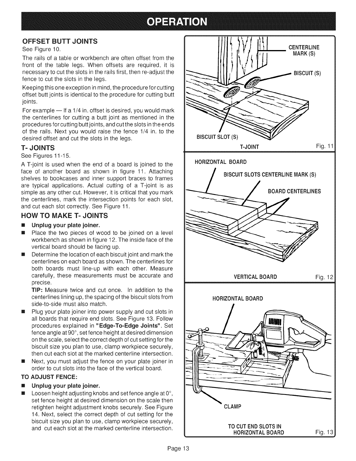
T- JOINTS
See Figures 11-15.
A T-joint is used when the end of a board is joined to the
face of another board as shown in figure 11. Attaching
shelves to bookcases and inner support braces to frames
are typical applications. Actual cutting of a T-joint is as
simple as any other cut. However, it is critical that you mark
the centedines, mark the intersection points for each slot,
and cut each slot correctly. See Figure 11.
HOW TO MAKE T- JOINTS
[] Unplug your plate joiner.
[] Place the two pieces of wood to be joined on a level
workbench as shown in figure 12. The inside face of the
vertical board should be facing up.
[] Determine the location of each biscuit joint and markthe
centerlines on each board as shown. The centerlines for
both boards must line-up with each other. Measure
carefully, these measurements must be accurate and
precise.
TIP: Measure twice and cut once. In addition to the
centerlines liningup, the spacing of the biscuit slots from
side-to-side must also match.
[] Plug your plate joiner into power supply and cut slots in
all boards that require end slots. See Figure 13, Follow
procedures explained in "Edge-To-Edge Joints". Set
fence angle at 90°, set fence height at desired dimension
on the scale, select the correct depth of cut setting for the
biscuit size you plan to use, clamp workpiece securely,
then cut each slot at the marked centerline intersection.
[] Next, you must adjust the fence on your plate joiner in
order to cut slots into the face of the vertical board.
TO ADJUST FENCE:
[]
[]
Unplug your plate joiner.
Loosen height adjusting knobs and set fence angle at 0°,
set fence height at desired dimension on the scale then
retighten height adjustment knobs securely. See Figure
14, Next, select the correct depth of cut setting for the
biscuit size you plan to use, clamp workpiece securely,
and cut each slot at the marked centedine intersection.
CENTERUNE
MARK(S)
BISCUIT(S)
BISCUITSLOT(S)
T-JOINT Fig. 11
HORIZONTALBOARD
BISCUITSLOTSCENTERUNEMARK(S)
BOARDCENTERUNES
VERTICALBOARD Fig. 12
HORIZONTALBOARD
CLAMP
TO CUTENDSLOTSIN
HOREONTALBOARD Fig. 13
Page13
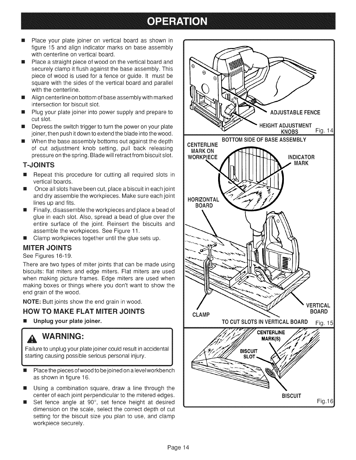
[] Placeyourplatejoineronverticalboardas shownin
figure15andalignindicatormarksonbaseassembly
withcenterlineonverticalboard.
[] Placea straightpieceofwoodontheverticalboardand
securelyclampit flushagainstthebaseassembly.This
pieceofwoodis usedfora fenceorguide.It mustbe
squarewiththesidesof theverticalboardandparallel
withthecenterline.
[] Aligncenterlineonbottomofbaseassemblywithmarked
intersectionforbiscuitslot.
[] Plugyourplatejoinerintopowersupplyandprepareto
cutslot.
[] Depresstheswitchtriggertoturnthepoweronyourplate
joiner,thenpushitdowntoextendthebladeintothewood.
[] Whenthebaseassemblybottomsoutagainstthedepth
of cut adjustmentknob setting,pull back releasing
pressureonthespring.Bladewillretractfrombiscuitslot.
T-JOINTS
[] Repeat this procedure for cutting all required slots in
vertical boards.
[] Once all slots have been cut, place a biscuit in each joint
and dry assemble the workpieces. Make sure each joint
lines up and fits.
[] Finally, disassemble the workpieces and place a bead of
glue in each slot. Also, spread a bead of glue over the
entire surface of the joint. Reinsert the biscuits and
assemble the workpieces. See Figure 11.
[] Clamp workpieces together until the glue sets up.
MITER JOINTS
See Figures 16-19.
There are two types of miter joints that can be made using
biscuits: flat miters and edge miters. Flat miters are used
when making picture frames. Edge miters are used when
making boxes or things where you don't want to show the
end grain of the wood.
NOTE: Butt joints show the end grain in wood.
HOW TO MAKE FLAT MITER JOINTS
[] Unplug your plate joiner.
,A WARNING:
Failure to unplug your plate joiner could result inaccidental
starting causing possible serious personal injury.
[]
[]
[]
Place the pieces of wood to be joined on a level workbench
as shown in figure 16.
Using a combination square, draw a line through the
center of each joint perpendicular to the mitered edges.
Set fence angle at 90 °, set fence height at desired
dimension on the scale, select the correct depth of cut
setting for the biscuit size you plan to use, and clamp
workpiece securely.
ADJUSTABLEFENCE
HEIGHTADJUSTMENT
KNOBS Fig. 1
BOTTOMSIDEOF BASEASSEMBLY
CENTERLINE
MARKON
WORKPIECE I
HORIZONTAL
BOARD
INDICATOR
MARK
VERTICAL
CLAMP BOARD
TO CUTSLOTSIN VERTICALBOARD Fig. 15
BISCUIT Fig.16
Page14
[] Alignindicatormarkonfencewiththecenterlineonthe
workpiece.
[] Plugyourplatejoinerintopowersupplyandprepareto
cutslot.
[] Depresstheswitchtriggertoturnthepoweronyourplate
joiner,thenpushit forwardtoextendthebladeintothe
wood.
[] Whenthebaseassemblybottomsoutagainstthedepth
of cut adjustmentknobsetting,pull backreleasing
pressureonthespring.Bladewillretractfrombiscuitslot.
[] Repeatthis procedurefor cuttingmatingslotand all
requiredmiterjointslots.
[] Onceallslotshavebeencut,placeabiscuitineachjoint
anddryassembletheworkpieces.Makesureeachjoint
linesupandfits.
[] Finally,disassembletheworkpiecesandplaceabeadof
glueineachslot.Also,spreada beadof glueoverthe
entiresurfaceof thejoint. Reinsertthe biscuitsand
assembletheworkpieces.SeeFigure16.
[] Clampworkpiecestogetheruntilthegluesetsup.
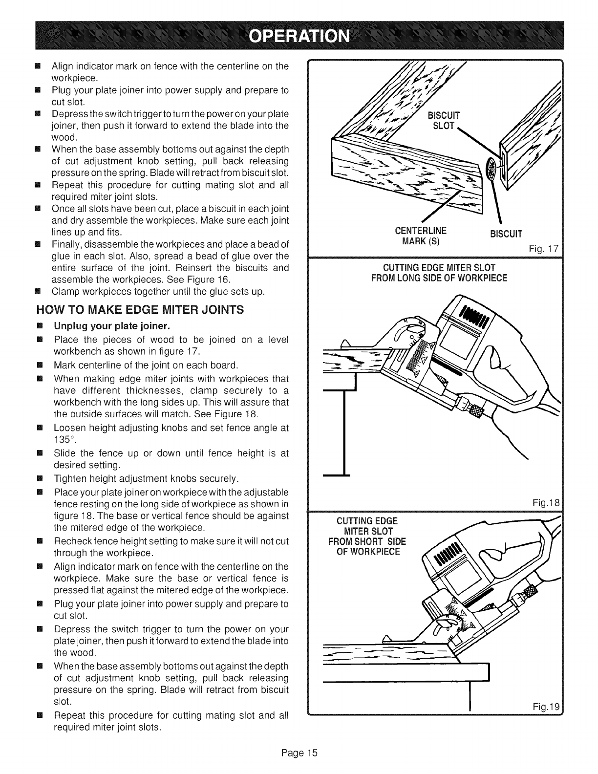
HOW TO MAKE EDGE MITER JOINTS
[] Unplug your plate joiner.
[] Place the pieces of wood to be joined on a level
workbench as shown in figure 17.
[] Mark centerline of the joint on each board.
[] When making edge miter joints with workpieces that
have different thicknesses, clamp securely to a
workbench with the long sides up. This will assure that
the outside surfaces will match. See Figure 18.
[] Loosen height adjusting knobs and set fence angle at
135 °.
[] Slide the fence up or down until fence height is at
desired setting.
[] Tighten height adjustment knobs securely.
[] Place your plate joiner on workpiece with the adjustable
fence resting on the long side of workpiece as shown in
figure 18. The base or vertical fence should be against
the mitered edge of the workpiece.
[] Recheck fence height setting to make sure it will not cut
through the workpiece.
[] Align indicator mark on fence with the centerline on the
workpiece. Make sure the base or vertical fence is
pressed flat against the mitered edge of the workpiece.
[] Plug your plate joiner into power supply and prepare to
cut slot.
[] Depress the switch trigger to turn the power on your
plate joiner, then push it forward to extend the blade into
the wood.
[] When the base assembly bottoms out against the depth
of cut adjustment knob setting, pull back releasing
pressure on the spring. Blade will retract from biscuit
slot.
[] Repeat this procedure for cutting mating slot and all
required miter joint slots.
CENTERLINE BISCUIT
MARK(S)
CUTTINGEDGEMITERSLOT
FROMLONGSIDEOF WORKPIECE
Fig. 17
\
CUTTINGEDGE
MITERSLOT
FROMSHORT SIDE
OF WORKPIECE
Fig.18
Page 15
[] Onceallslotshavebeencut,placeabiscuitineachjoint
anddryassembletheworkpieces.Makesureeachjoint
linesupandfits.
[] Finally,disassembleworkpiecesandplacea beadof
glueineachslot.Also,spreada beadof glueoverthe
entiresurfaceof thejoint.Reinsertthe biscuitsand
assembleworkpieces.SeeFigure17.
[] Clampworkpiecestogetheruntilthegluesetsup.
Iftheworkpiecesarethesamethickness,clampsecurelyto
a workbenchwiththeshortsidesup.SeeFigure19.Set
fenceangleat45°. Placeyourplatejoinerontheworkpiece
withtheadjustablefencerestingon theshortsideof the
workpieceandthebaseorverticalfenceagainstthemitered
edgeof the workpiece.Followsteps9-17aboveto cut
requiredslots.
REMEMBER:Beforecuttingslots,makesurebladewillnot
cut throughtheworkpieceandthat boththeverticaland
horizontalfencesarepressedflatagainstthemiterededge
andfaceoftheworkpiece.
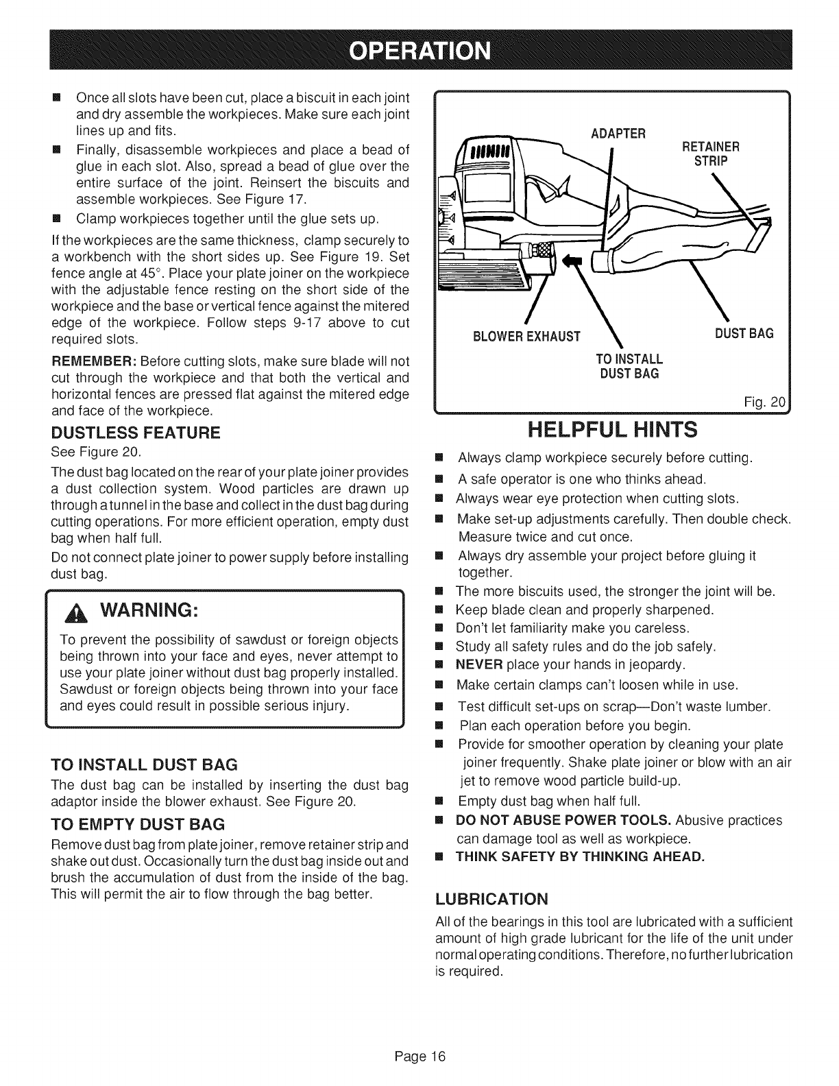
DUSTLESS FEATURE
See Figure 20.
The dust bag located on the rear of your plate joiner provides
a dust collection system. Wood particles are drawn up
through atunnel in the base and collect in the dust bag during
cutting operations. For more efficient operation, empty dust
bag when half full.
Do not connect plate joiner to power supply before installing
dust bag.
WARNING:
To prevent the possibiNity of sawdust or foreign objects
being thrown into your face and eyes, never attempt to
use your plate joiner without dust bag properly installed.
Sawdust or foreign objects being thrown into your face
and eyes could result in possible serious injury.
TO INSTALL DUST BAG
The dust bag can be installed by inserting the dust bag
adaptor inside the blower exhaust. See Figure 20.
TO EMPTY DUST BAG
Remove dust bag from plate joiner, remove retainer strip and
shake out dust. Occasionally turn the dust bag inside out and
brush the accumulation of dust from the inside of the bag.
This will permit the air to flow through the bag better.
ADAPTER
BLOWEREXHAUST DUSTBAG
TO iNSTALL
DUSTBAG
_..___ Fig. 20
HELPFUL HINTS
[] Always clamp workpiece securely before cutting.
[] A safe operator is one who thinks ahead.
[] Always wear eye protection when cutting slots.
[] Make set-up adjustments carefully. Then double check.
Measure twice and cut once.
[] Always dry assemble your project before gluing it
together.
[] The more biscuits used, the stronger the joint will be.
[] Keep blade clean and properly sharpened.
[] Don't let familiarity make you careless.
[] Study all safety rules and do the job safely.
[] NEVER place your hands in jeopardy.
[] Make certain clamps can't loosen while in use.
[] Test difficult set-ups on scrap--Don't waste lumber.
[] Plan each operation before you begin.
[] Provide for smoother operation by cleaning your plate
joiner frequently. Shake plate joiner or blow with an air
jet to remove wood particle build-up.
[] Empty dust bag when half full.
[] DO NOT ABUSE POWER TOOLS. Abusive practices
can damage tool as well as workpiece.
[] THINK SAFETY BY THINKING AHEAD.
LUBRICATION
All of the bearings in this tool are lubricated with a sufficient
amount of high grade lubricant for the life of the unit under
normal operating conditions. Therefore, no further lubrication
is required.
Page 16
WARNING:
When servicing, use only identical Ryobi replacement
parts. Use of any other part may create a hazard or
cause product damage.
CLEANING BASE ASSEMBLY /DUST BAG
TUNNEL
See Figures 21-23.
After extended use, wood particles and resin may build up
inside the base assembly of your plate joiner and clog the
path for wood particles going into dust bag. Wood particles
packing up in this area, not only defeats the dustless feature
of your plate joiner, it also makes cutting biscuit slots more
difficult.
HOW TO CLEAN BASE ASSEMBLY
[] Unplug your plate joiner.
WARNING:
Failure to unplug your plate joiner could result inaccidental
starting causing possible serious personal injury.
[] Remove dust bag.
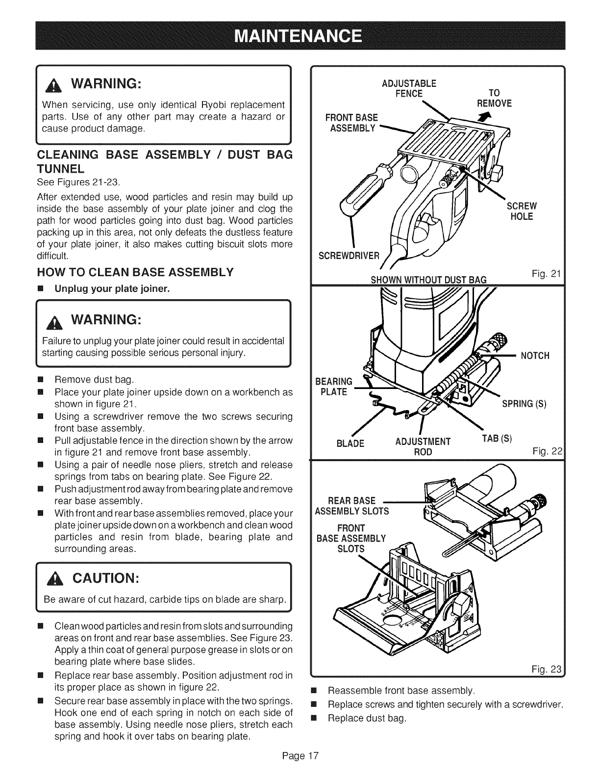
[] Place your plate joiner upside down on a workbench as
shown in figure 21.
[] Using a screwdriver remove the two screws securing
front base assembly.
[] Pull adjustable fence in the direction shown by the arrow
in figure 21 and remove front base assembly.
[] Using a pair of needle nose pliers, stretch and release
springs from tabs on bearing plate. See Figure 22.
[] Push adjustment rod away from bearing plate and remove
rear base assembly.
[] With front and rear base assemblies removed, place your
plate joiner upside down on aworkbench and clean wood
particles and resin from blade, bearing plate and
surrounding areas.
CAUTION"
Be aware of cut hazard, carbide tips on blade are sharp.
[] Clean wood particles and resin from slots and surrounding
areas on front and rear base assemblies. See Figure 23.
Apply a thin coat of general purpose grease in slots or on
bearing plate where base slides.
[] Replace rear base assembly. Position adjustment rod in
its proper place as shown in figure 22.
[] Secure rear base assembly in place with the two springs.
Hook one end of each spring in notch on each side of
base assembly. Using needle nose pliers, stretch each
spring and hook it over tabs on bearing plate.
ADJUSTABLE
FENCE TO
REMOVE
F ONTBASE
SHOWNWITHOUTDUSTBAG Fig. 21
Page 17
NOTCH
BEARING
PLATE
SPRING(S)
BLADE ADJUSTMENT TAB (S)
ROD Fig. 22
REARBASE
ASSEMBLYSLOTS
FRONT
BASEASSEMBLY
SLOTS
Fig. 23
[] Reassemble front base assembly.
[] Replace screws and tighten securely with a screwdriver.
[] Replace dust bag.
BLADE REPLACEMENT
See Figures 24-27.
After extended use, the blade on your plate joiner may
become dull and need replacing. If you accidentally hit a
nail or other blunt object, itwill break the carbide tips on the
blade. These situations also require replacing the blade.
HOW TO REPLACE THE BLADE
[] Unplug your plate joiner.
WARNING:
Failure to unplug your plate joiner could result inaccidental
starting causing possible serious personal injury.
[] Remove dust bag.
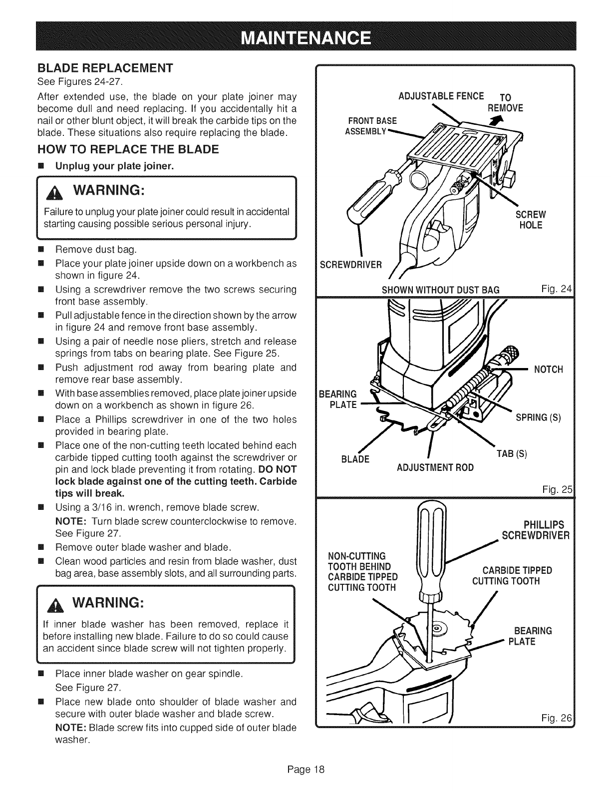
[] Place your plate joiner upside down on a workbench as
shown in figure 24.
[] Using a screwdriver remove the two screws securing
front base assembly.
[] Pull adjustable fence in the direction shown by the arrow
in figure 24 and remove front base assembly.
[] Using a pair of needle nose pliers, stretch and release
springs from tabs on bearing plate. See Figure 25.
[] Push adjustment rod away from bearing plate and
remove rear base assembly.
[] With base assemblies removed, place plate joiner upside
down on a workbench as shown in figure 26.
[] Place a Phillips screwdriver in one of the two holes
provided in bearing plate.
[] Place one of the non-cutting teeth located behind each
carbide tipped cutting tooth against the screwdriver or
pin and lock blade preventing it from rotating. DO NOT
lock blade against one of the cutting teeth. Carbide
tips will break.
[] Using a 3/16 in. wrench, remove blade screw.
NOTE: Turn blade screw counterclockwise to remove.
See Figure 27.
[] Remove outer blade washer and blade.
[] Clean wood particles and resin from blade washer, dust
bag area, base assembly slots, and all surrounding parts.
WARNING:
If inner blade washer has been removed, replace it
before installing new blade. Failure to do so could cause
an accident since blade screw will not tighten properly.
[]
[]
Place inner blade washer on gear spindle.
See Figure 27.
Place new blade onto shoulder of blade washer and
secure with outer blade washer and blade screw.
NOTE: Blade screw fits into cupped side of outer blade
washer.
ADJUSTABLEFENCE TO
REMOVE
FRONTBASE
ASS
t SCREW
HOLE
SCREWDRIVER
SHOWNWITHOUTDUSTBAG Fig. 24
NOTCH
BEARING
PLATE
SPRING(S)
BLADE ADJUSTMENTROD
TAB(s)
Fig. 25
PHiLLiPS
// SCREWDRIVER
CUTTINGTOOTH CUTTINGTOOTH
BEARING
_ PLATE
II /1 Fig. 26
Page 18
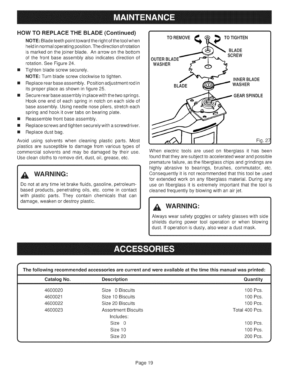
HOW TO REPLACE THE BLADE (Continued)
NOTE: Blade teeth point toward the right of the tool when
held in normal operating position. The direction of rotation
is marked on the joiner blade. An arrow on the bottom
of the front base assembly also indicates direction of
rotation. See Figure 24.
[] Tighten blade screw securely.
NOTE: Turn blade screw clockwise to tighten.
[] Replace rear base assembly. Position adjustment rod in
its proper place as shown in figure 25.
[] Secure rear base assembly in place with the two springs.
Hook one end of each spring in notch on each side of
base assembly. Using needle nose pliers, stretch each
spring and hook it over tabs on bearing plate.
[] Reassemble front base assembly.
[] Replace screws and tighten securelywith a screwdriver.
[] Replace dust bag.
Avoid using solvents when cleaning plastic parts. Most
plastics are susceptible to damage from various types of
commercial solvents and may be damaged by their use.
Use clean cloths to remove dirt, dust, oil, grease, etc.
WARNING:
Do not at any time let brake fluids, gasoline, petroleum-
based products, penetrating oils, etc. come in contact
with plastic parts. They contain chemicals that can
damage, weaken or destroy plastic.
TO REMOVE _ TO TIGHTEN
BLADE
SCREW
OUTERBLADE
WASHER
BLADE
INNERBLADE
WASHER
GEARSPINDLE
Fig. 2_
When electric tools are used on fiberglass it has been
found that they are subject to accelerated wear and possible
premature failure, as the fiberglass chips and grindings are
highly abrasive to bearings, brushes, commutator, etc.
Consequently it is not recommended that this tool be used
for extended work on any fiberglass material. During any
use on fiberglass it is extremely important that the tool is
cleaned frequently by blowing with an air jet.
WARNING"
Always wear safety goggles or safety glasses with side
shields during power tool operation or when blowing
dust. If operation is dusty, also wear a dust mask.
The following recommended accessories are current and were available at the time this manual was printed:
Catalog No. Description Quantity
4600020
4600021
4600022
4600023
Size 0 Biscuits 100 Pcs.
Size 10 Biscuits 100 Pcs.
Size 20 Biscuits 100 Pcs.
Assortment Biscuits Total 400 Pcs.
Includes:
Size 0 100 Pcs.
Size 10 100 Pcs.
Size 20 200 Pcs.
Page 19
i so.o ,o° i
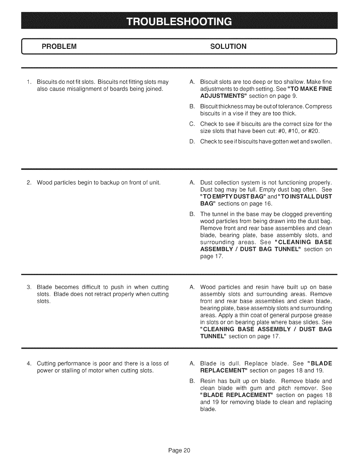
1. Biscuits do not fit slots. Biscuits not fitting slots may A.
also cause misalignment of boards being joined.
a.
C.
Biscuit slots are too deep or too shallow. Make fine
adjustments to depth setting. See "TO MAKE FINE
ADJUSTMENTS" section on page 9.
Biscuit thickness may be out of tolerance. Compress
biscuits in a vise if they are too thick.
Check to see if biscuits are the correct size for the
size slots that have been cut: #0, #10, or #20.
D. Check to see if biscuits have gotten wet and swollen.
2. Wood particles begin to backup on front of unit. A.
a.
Dust collection system is not functioning properly.
Dust bag may be full. Empty dust bag often. See
"TO EMPTY DUST BAG" and "TO INSTALL DUST
BAG" sections on page 16.
The tunnel in the base may be clogged preventing
wood particles from being drawn into the dust bag.
Remove front and rear base assemblies and clean
blade, bearing plate, base assembly slots, and
surrounding areas. See "CLEANING BASE
ASSEMBLY /DUST BAG TUNNEL" section on
page 17.
.Blade
slots.
slots.
becomes difficult to push in when cutting
Blade does not retract properly when cutting
A. Wood particles and resin have built up on base
assembly slots and surrounding areas. Remove
front and rear base assemblies and clean blade,
bearing plate, base assembly slots and surrounding
areas. Apply a thin coat of general purpose grease
in slots or on bearing plate where base slides. See
"CLEANING BASE ASSEMBLY /DUST BAG
TUNNEL" section on page 17.
.Cutting performance is poor and there is a loss of
power or stalling of motor when cutting slots.
A.
a.
Blade is dull. Replace blade. See "BLADE
REPLACEMENT" section on pages 18 and 19.
Resin has built up on blade. Remove blade and
clean blade with gum and pitch remover. See
"BLADE REPLACEMENT" section on pages 18
and 19 for removing blade to clean and replacing
blade.
Page 20

Page21

OPERATOR'S
PLATE J
J ;1-1
DOUBLE iNSULATED
UAL
, SERVICE
Now that you have purchased your tool, should a need ever exist for repair parts or service,
simply contact your nearest Ryobi Authorized Service Center. Be sure to provide all pertinent
facts when you call or visit. Please call 1-800-525-2579 for your nearest Ryobi Authorized
Service Center. You can also check our web site at www.ryobitools.com for a complete list
of Authorized Service Centers.
, MODEL NO.
The model number of your tool will be found on a plate attached to the motor housing. Please
record the model number and serial number in the space provided below.
• MODEL NUMBER JM81-1
• SERIAL NUMBER
RYOB! TECHNOLOGIES, INC.
1428 Pearman Dairy Road Anderson SC 29625
Post Office Box 1207, Anderson SC 29622-1207
Phone 1-800-525-2579
www.ryobitools.com
972000-983
