Racom RA400-400 UHF NARROWBAND RADIOMODEM User Manual navod RipEX new a
Racom UHF NARROWBAND RADIOMODEM navod RipEX new a
UserManual.wiki
>
Racom
>
RA400 400 User Manual
Users Manual
Navigation menu
Upload a User Manual
Namespaces
Wiki Guide
HTML
PDF
Info
Views
User Manual
Discussion / Help
Navigation
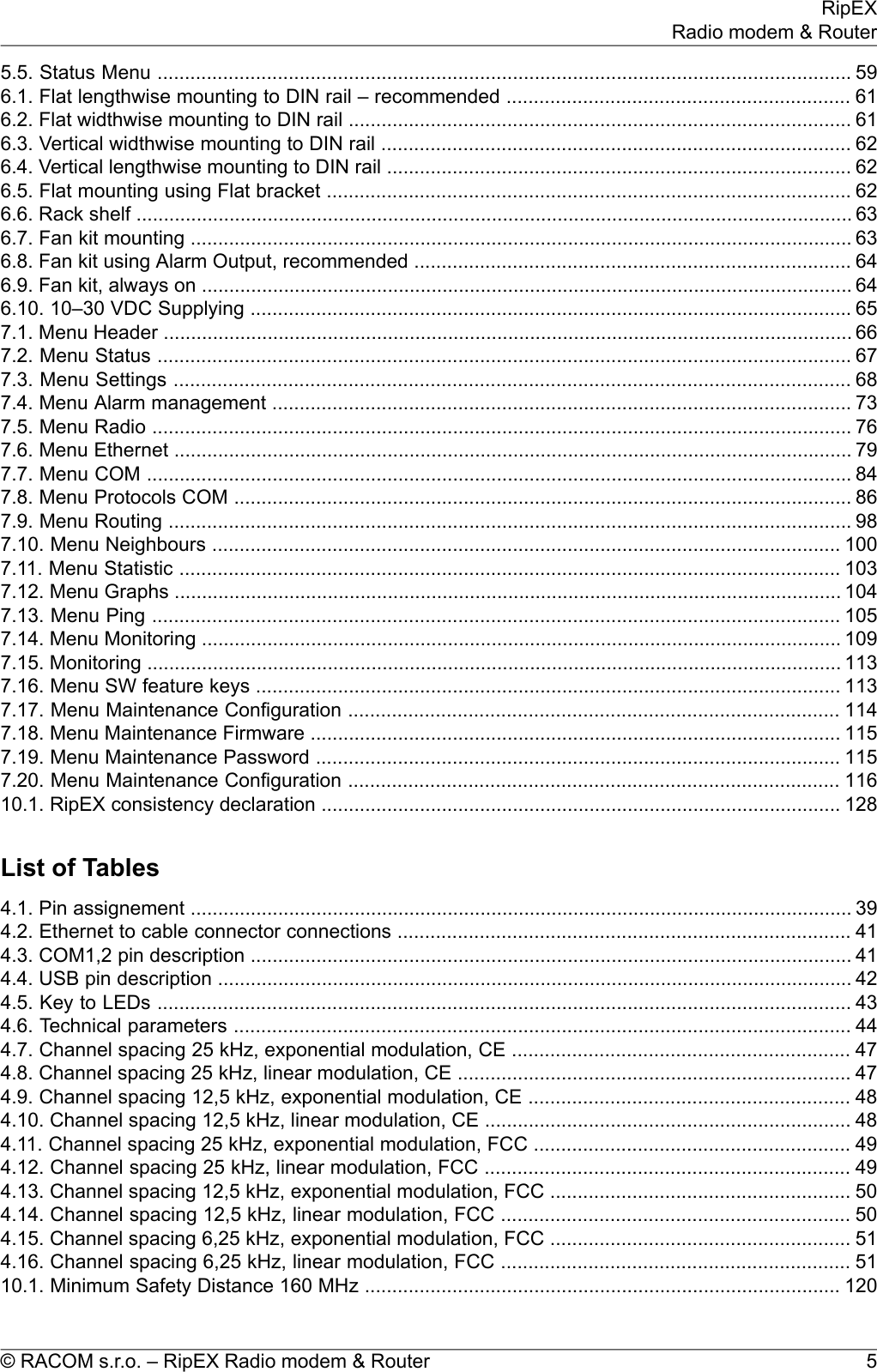

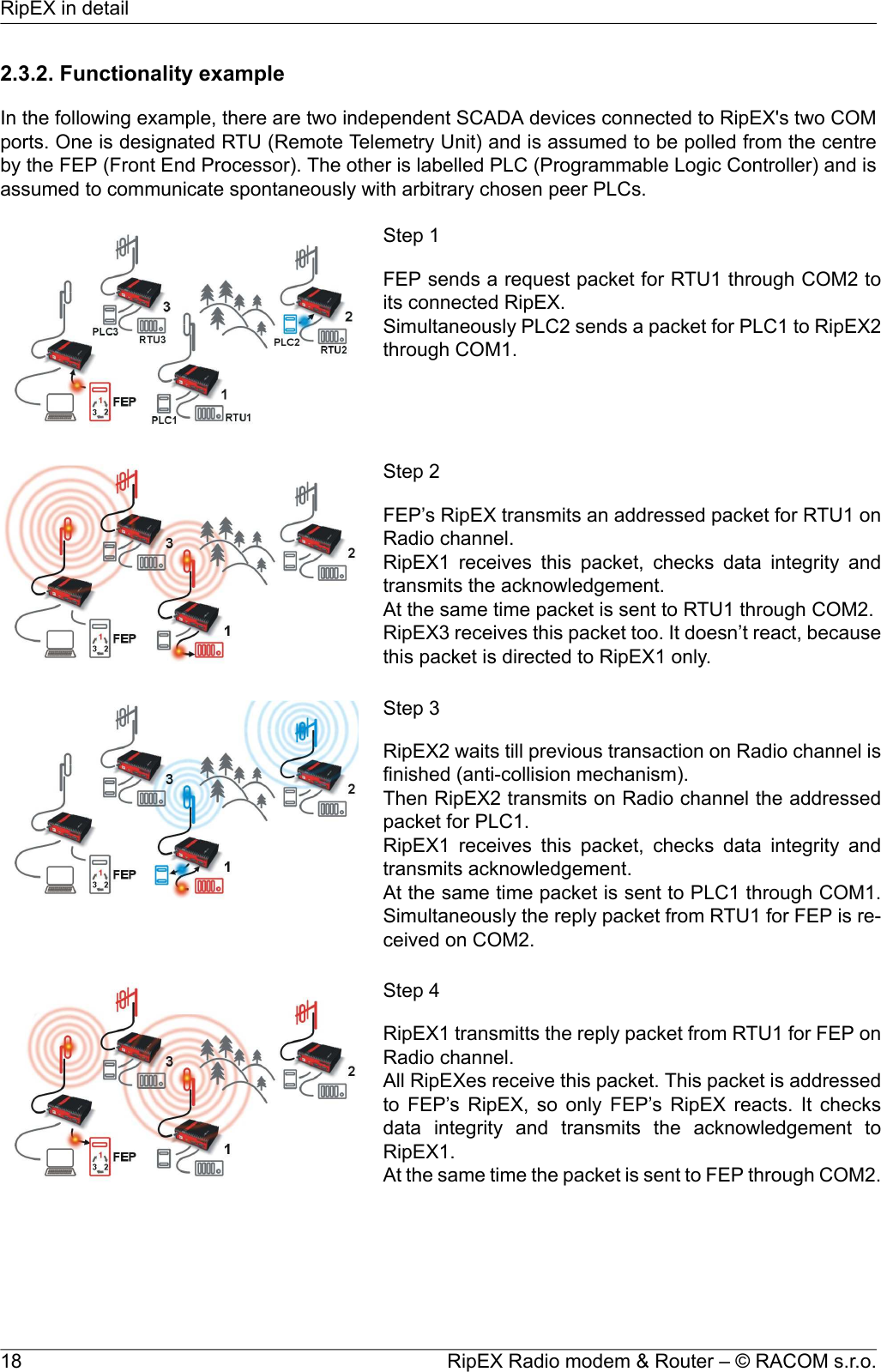
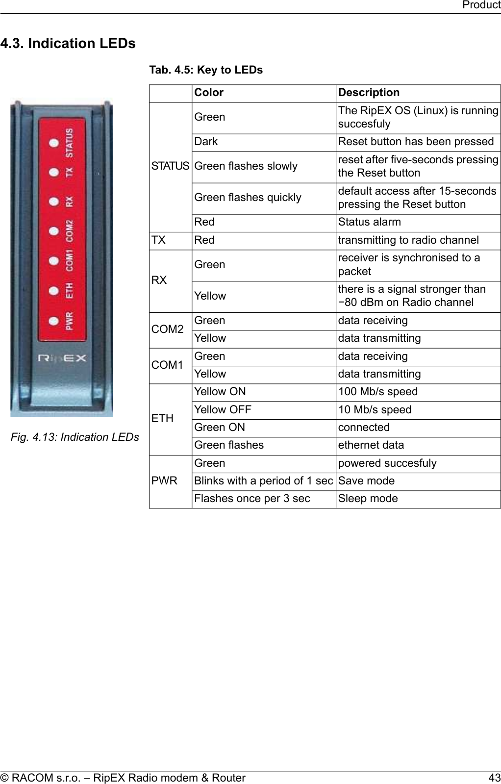
![2.6.1. LogsThere are ‘Neighbours’ and Statistic logs in RipEX. For both logs there is a history of 20 log filesavailable, so the total history of saved values is 20 days (assuming the default value of 1440 min. isused as the Log save period).NeighboursThe ‘Neighbours’ log provides information about neighbouring units (RipEX’s which can be accesseddirectly over the radio channel, i.e. without a repeater). Every RipEX on the network regularly broadcastsits status, the set of so called “Watched values”: the probability of packet loss when transmitting dataover the radio channel, current supply voltage, internal temperature, measured RF output power, theVoltage Standing Wave Ratio on the antenna feed line and the total number of packets received from/ transmitted to ETH, COM1, COM2 interfaces. In addition, the RipEX that records this data in its logalso keeps track of how many times it listened to its neighbouring unit as well as of the RSS and DQrecorded. See Adv. Conf., Diagnostic for more.StatisticThe ‘Statistic’ log provides information about the volume of data traffic on all interfaces: radio, ETH,COM1, COM2. It offers detailed information about the number of transmitted packets, their size andthe throughput per second. Moreover, a detailed division into user and service packets is available forthe radio channel. See chapter Adv. Conf., Diagnostic for more.2.6.2. GraphsAn independent database periodically stores the Watched values (see 'Neighbours' log above) fromup to five neighbouring RipEX's and from the local one, there including most important values from theStatistic log. All these values can be displayed as graphs.The graphs are available in summary and detailed versions. Detailed logging is triggered on when athreshold value has been reached for the specific item to enable a more detailed investigation into theunits’ operation when an alarm event occurs. Each graph can display two different elements at once,including their set thresholds. Each of the values may originate from a different RipEX unit.See chapter Adv. Conf., Graphs for more.2.6.3. SNMPRipEX implements an SNMP client ver. 1. The values provided by RipEX are shown in the MIB table.RipEX also allows generating SNMP traps when thresholds have been reached for the monitored values:RSScom, DQcom, TXLost[%], Ucc, Temp, PWR, VSWR, ETH[Rx/Tx], COM1[Rx/Tx], COM2[Rx/Tx],HW Alarm Input.See chapter RipEX App notes, SNMP for RACOM RipEX1for more.2.6.4. PingTo diagnose the individual radio links RipEX is equipped with an enhanced Ping tool. In addition to thestandard info such as the number of sent and received packets or the round trip time, it provides the1http://www.racom.eu/eng/products/m/ripex/app/snmp.htmlRipEX Radio modem & Router – © RACOM s.r.o.24RipEX in detail](https://usermanual.wiki/Racom/RA400-400/User-Guide-1712998-Page-24.png)
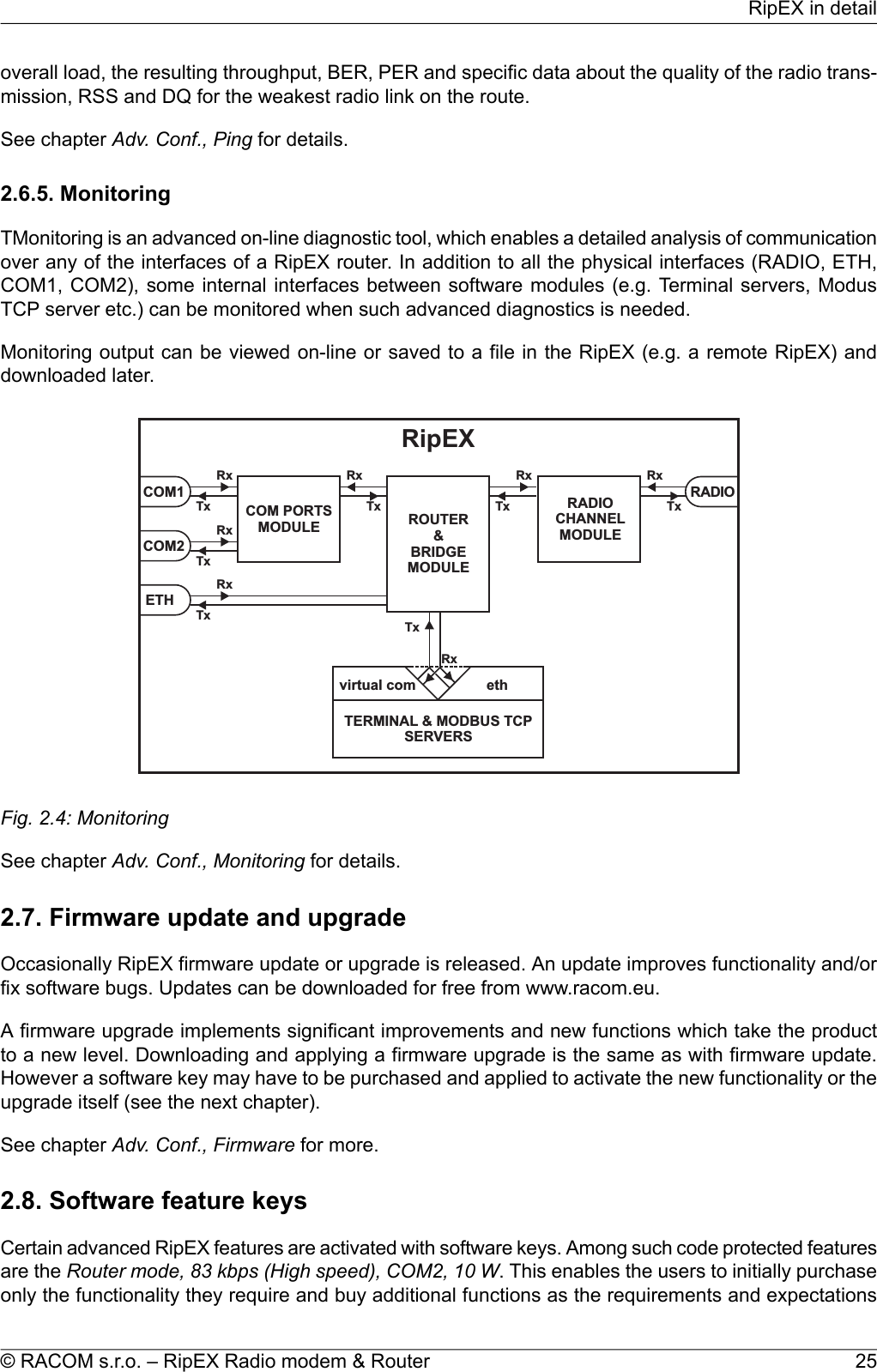
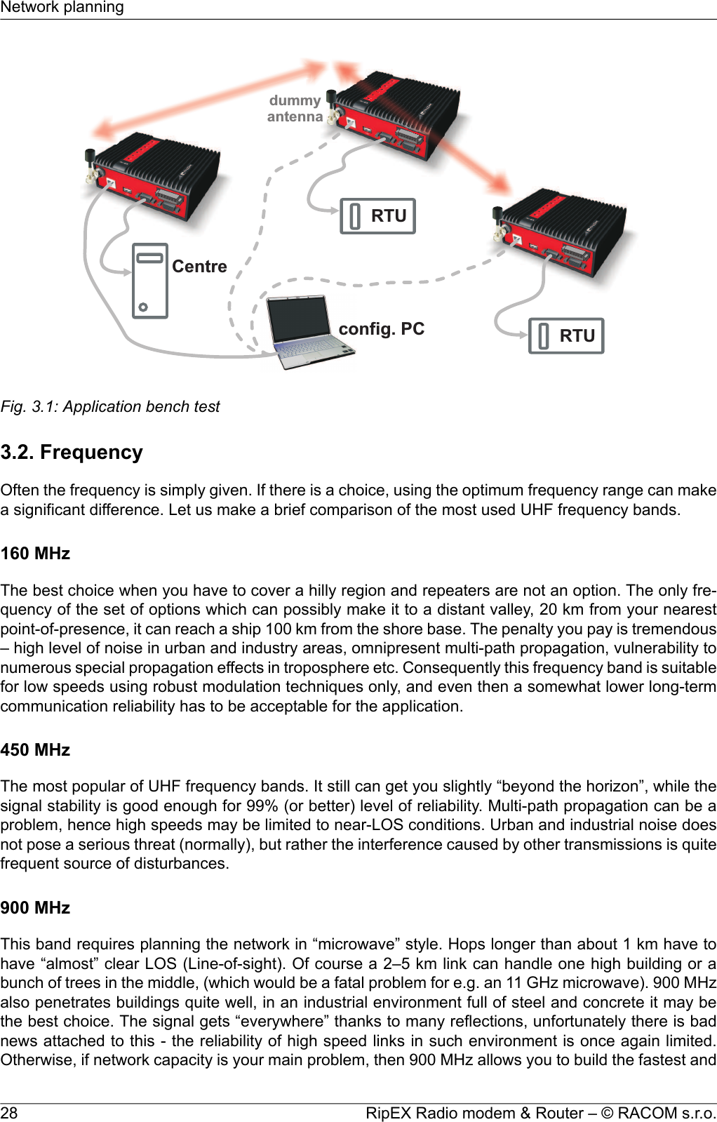
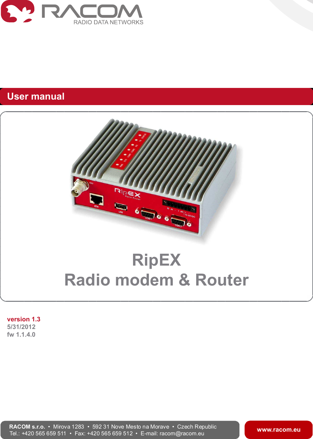
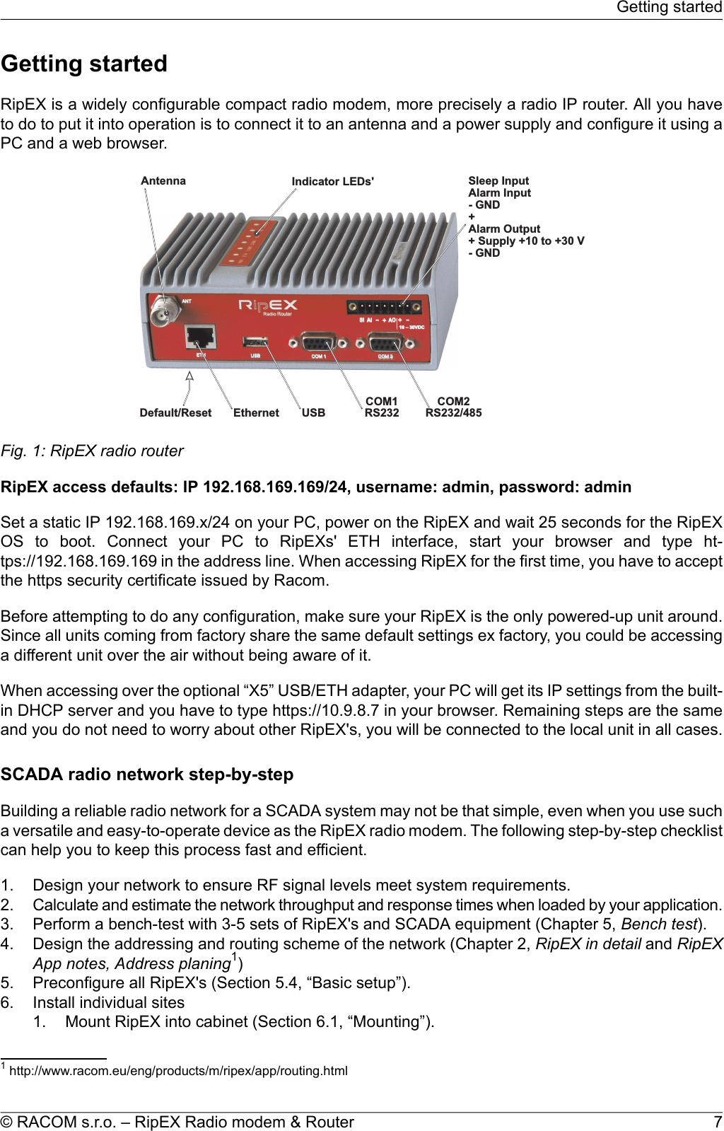
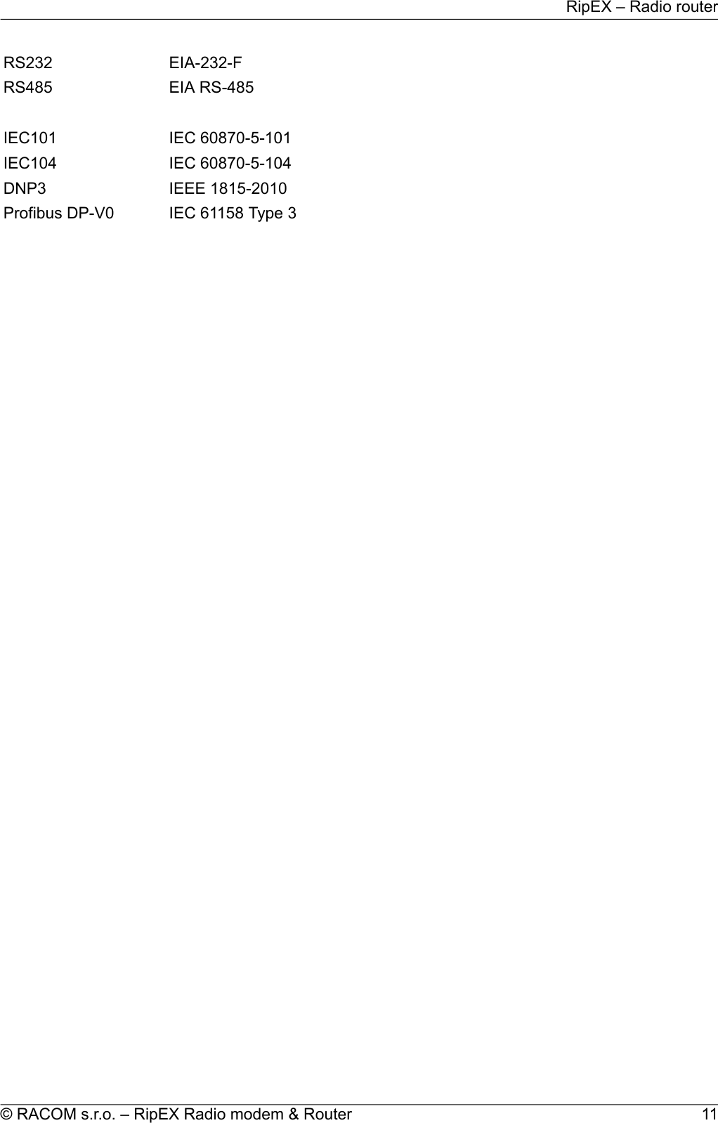
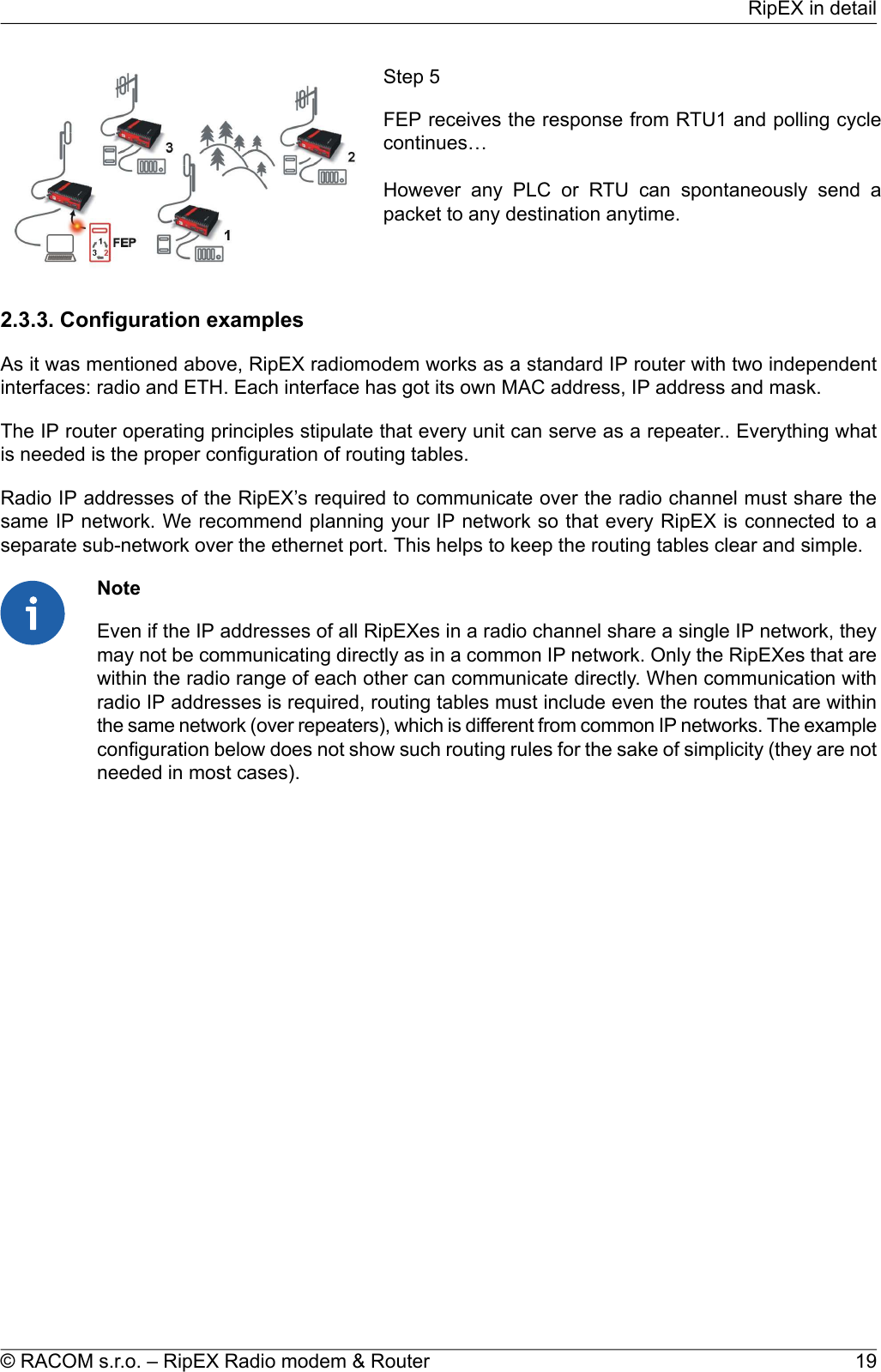
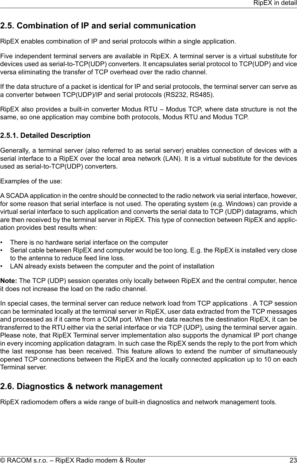
![most reliable links. The price you pay (compared to lower frequency bands) is really the price – morerepeaters and higher towers increase the initial cost. Long term reliable performance is the reward.The three frequency bands discussed illustrate the simple basic rules – the higher the frequency, thecloser to LOS the signal has to travel. That limits the distance over the Earth's surface – there is noother fundamental reason why shorter wavelengths could not be used for long distance communication.On the other hand, the higher the frequency, the more reliable the radio link is. The conclusion is thenvery simple – use the highest frequency band you can.3.3. Signal budgetFor every radio hop which may be used in the network, the signal level at the respective receiver inputhas to be calculated and assessed against requirements. The fundamental requirements are two – thedata rate, which is dictated by total throughput and response times required by the application, and theavailability, which is again derived from the required reliability of the application. The data rate translatesto receiver sensitivity and the availability (e.g. 99,9 % percent of time) results in size of the fade margin.The basic rule of signal budget says, that the difference between the signal level at the receiver inputand the guaranteed receiver sensitivity for the given data rate has to be greater than the fade marginrequired:RX signal [dBm] – RX sensitivity [dBm] >= Fade margin [dB]To calculate the RX signal level, we follow the RF signal path:TXoutputRXinputfeedlinelossfeedlinelosspathlossTXantennagainRXantennagain+ +Fig. 3.2: Signal pathexample:RX signal [dBm] =dBm (TX output 1 W)+30.0+ TX output [dBm]dB (20m cable RG-213 U, 400 MHz)-2.5- TX antenna feeder loss [dB]dBi (half-wave dipole, 0 dBd)+2.1+TX antenna gain [dBi]dB calculated from field measurement)-125.0- Path loss [dB]dB (7-al Yagi antenna, 7.6 dBd)+9.7+ RX antenna gain [dBi]dB (10 m cable RG-58 CU, 400 MHz)-3.1- RX antenna feeder loss [dB]dBm Received Signal Strength (RSS)= -88.8The available TX output power and guaranteed RX sensitivity level for the given data rate have to bedeclared by the radio manufacturer. RipEX values can be found in Table 4.6, “Technical parameters”.29© RACOM s.r.o. – RipEX Radio modem & RouterNetwork planning](https://usermanual.wiki/Racom/RA400-400/User-Guide-1712998-Page-29.png)
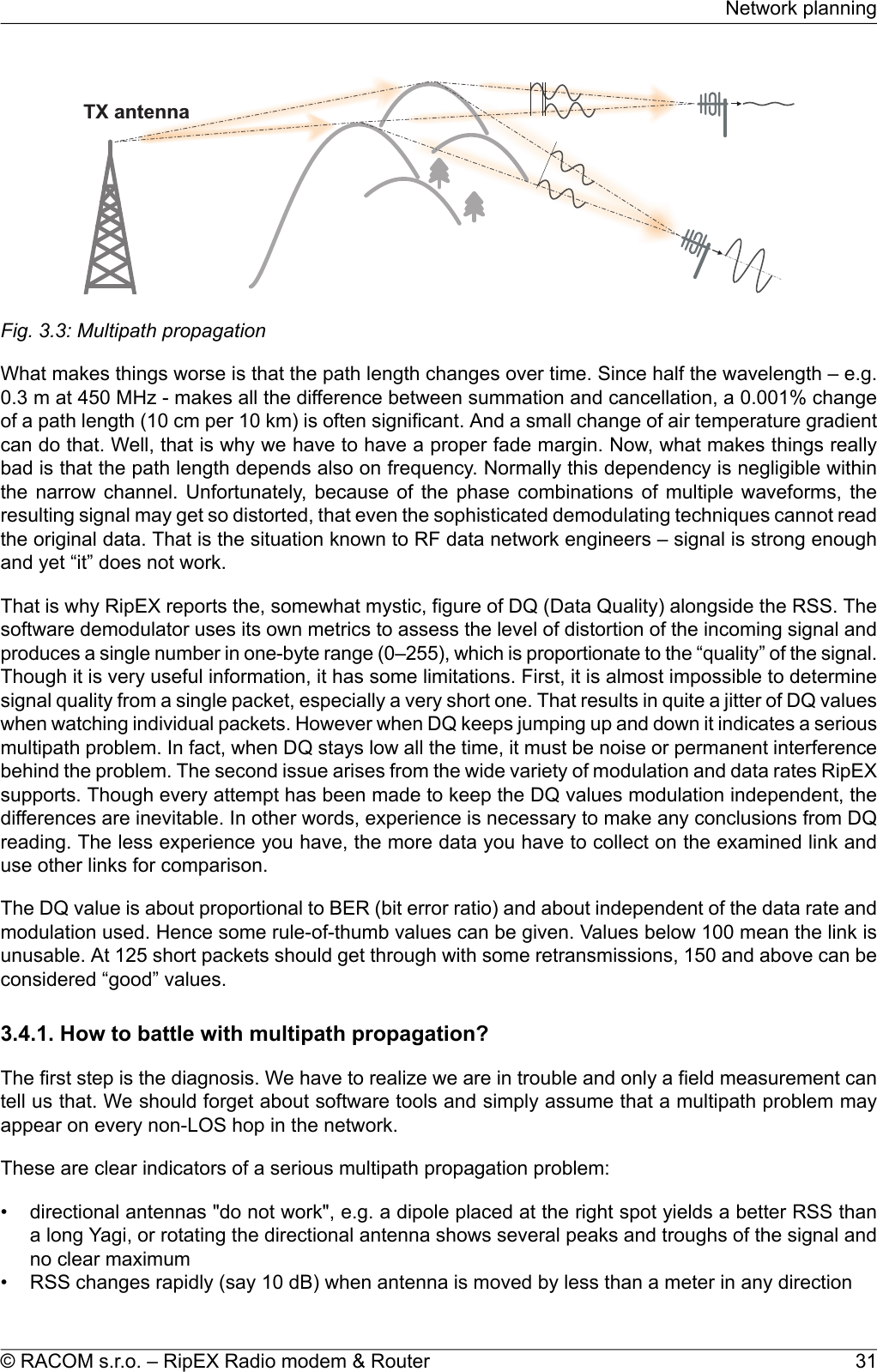
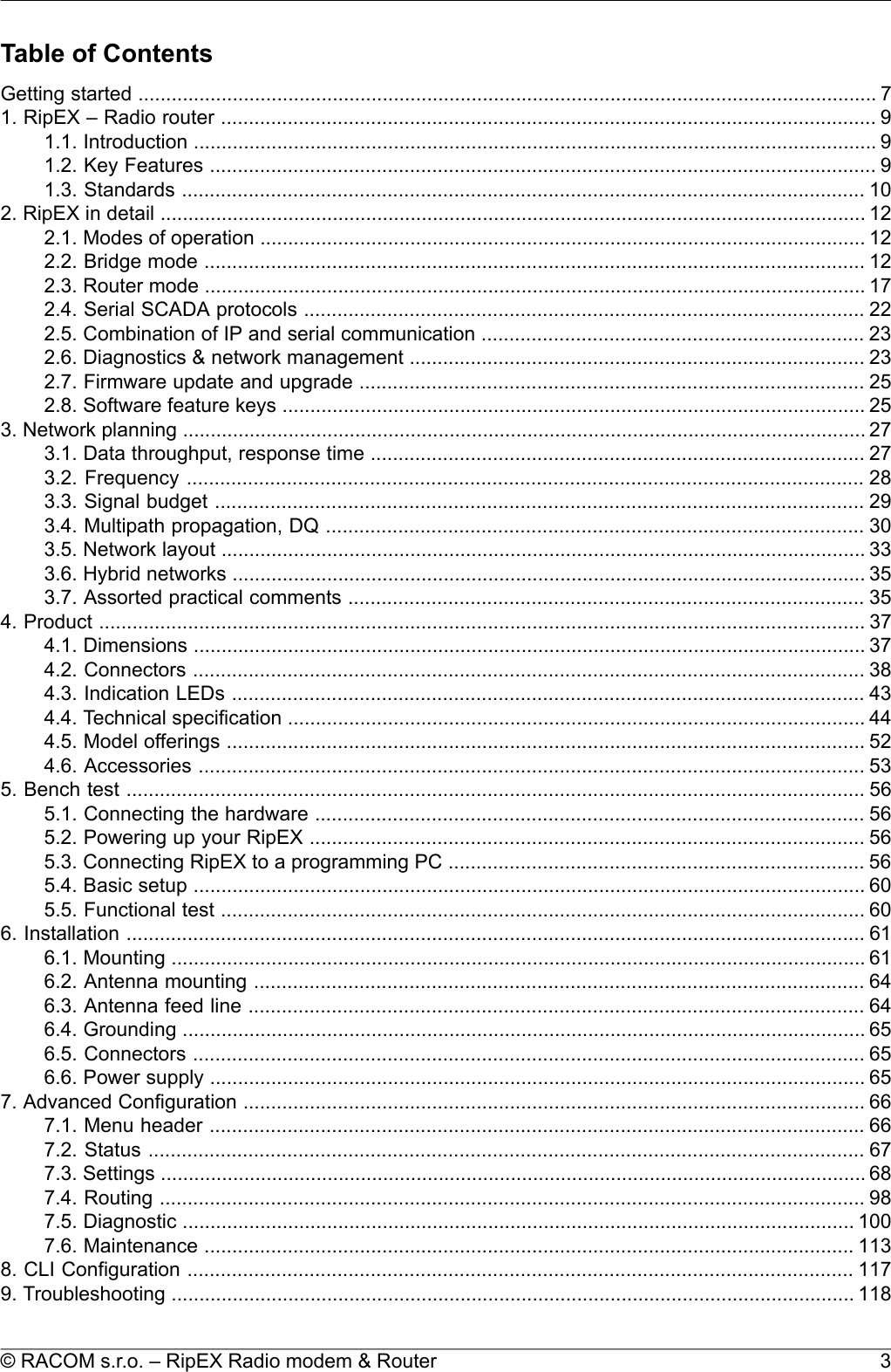
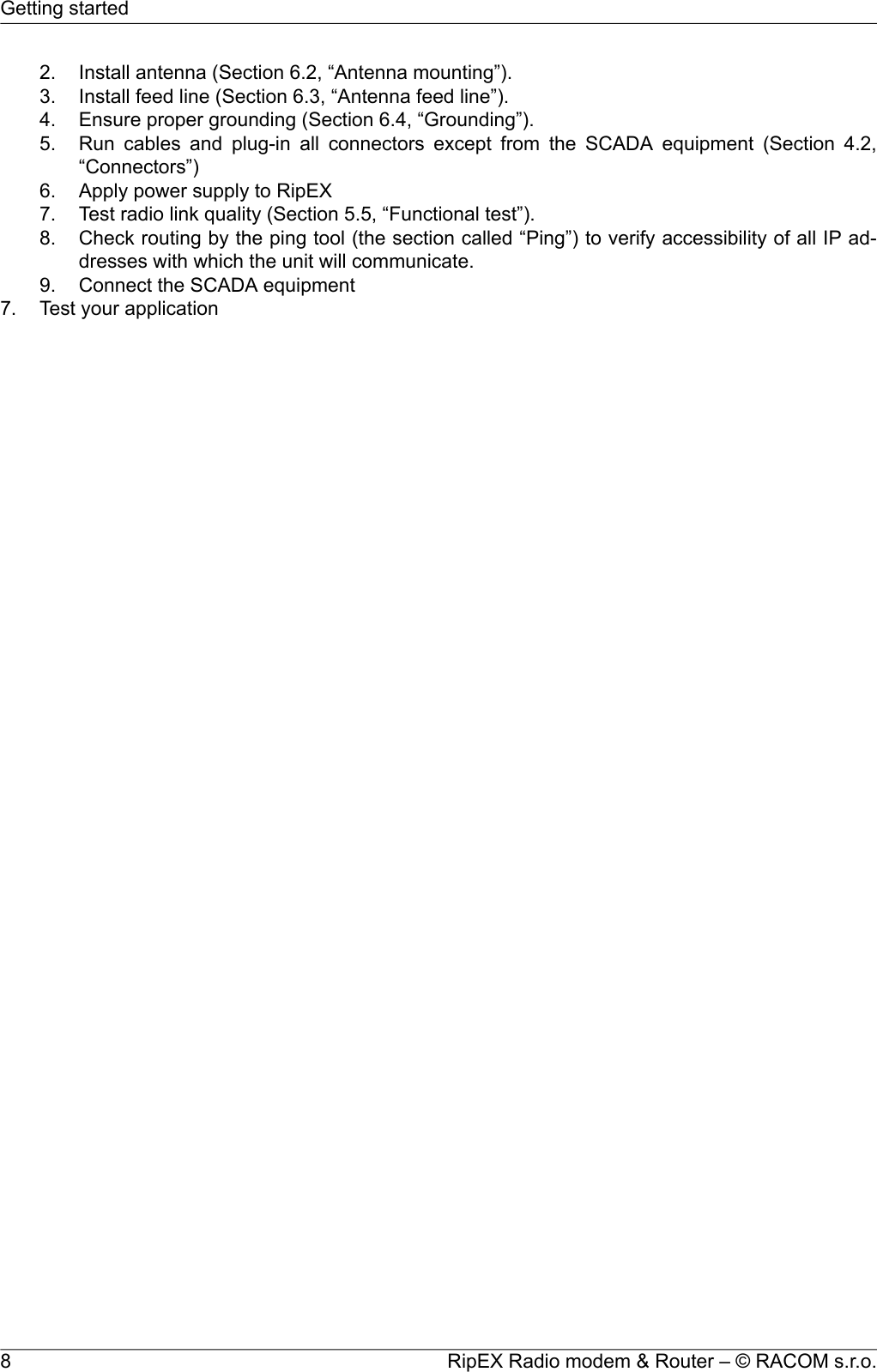
![Antenna gains and directivity diagrams have to be supplied by the antenna manufacturer. Note thatantenna gains against isotropic radiator (dBi) are used in the calculation. The figures of feeder cableloss per meter should be also known. Note that coaxial cable parameters may change considerablywith time, especially when exposed to an outdoor environment. It is recommended to add a 50-100 %margin for ageing to the calculated feeder loss.3.3.1. Path loss and fade marginThe path loss is the key element in the signal budget. Not only does it form the bulk of the total loss,the time variations of path loss are the reason why a fade margin has to be added. In reality, very oftenthe fade margin is the single technical figure which expresses the trade-off between cost and perform-ance of the network. The decision to incorporate a particular long radio hop in a network, despite thatits fade margin indicates 90 % availability at best, is sometimes dictated by the lack of investment in ahigher tower or another repeater. Note that RipEXs Auto-speed feature allows the use of a lower datarate over specific hops in the network, without the need to reduce the rate and consequently thethroughput in the whole network. Lower data rate means lower (= better) value of receiver sensitivity,hence the fade margin of the respective hop improves. See the respective Application note to learnmore on the Auto-speed feature.When the signal path profile allows for LOS between the TX and RX antennas, the standard formulafor free-space signal loss (below) gives reliable results:Path loss [dB] = 20 * log10 (distance [km]) + 20 * log10 (frequency [MHz]) + 32.5In the real world the path loss is always greater. UHF radio waves can penetrate obstacles (buildings,vegetation), can be reflected from flat objects, can bend over round objects, can disperse behind sharpedges – there are numerous ways how a radio signal can propagate in non-LOS conditions. The addi-tional loss when these propagation modes are involved (mostly combined) is very difficult to calculate.There are sophisticated methods used in RF design software tools which can calculate the path lossand its variations (statistical properties) over a computer model of terrain. Their accuracy is unfortunatelyvery limited. The more obstacles on the path, the less reliable is the result. Such a tool can be veryuseful in the initial phase of network planning, e.g. to do the first network layout for the estimate of totalthroughput, however field measurements of every non-LOS radio hop should be done before the finalnetwork layout is designed.Determining the fade margin value is even more difficult. Nevertheless the software tools mentionedcan give some guidance, since they can calculate the statistical properties of the signal. Generally thefade margin (for given availability) is proportional to the difference between the real path loss and theLOS path loss over the same distance. Then it is about inversely proportional to frequency (in the UHFrange at least). To give an example for 10 km, non-LOS, hop on 450 MHz, fade margin of 20 dB is abare minimum. A field test may help again, provided it is run for longer period of time (hours-days).RipEX diagnostic tools (ping) report the mean deviation of the RSS, which is a good indication of thesignal stability. A multiple of the mean deviation should be added to the fade margin.3.4. Multipath propagation, DQMultipath propagation is the arch-enemy of UHF data networks. The signal coming out of the receivingantenna is always a combination of multiple signals. The transmitted signal arrives via different paths,by the various non-LOS ways of propagation. Different paths have different lengths, hence the waveformsare in different phases when hitting the receiving antenna. They may add-up, they may cancel eachother out.RipEX Radio modem & Router – © RACOM s.r.o.30Network planning](https://usermanual.wiki/Racom/RA400-400/User-Guide-1712998-Page-30.png)