Racom RIPEX-154 VHF NARROWBAND RADIOMODEM User Manual RipEX Radio modem Router
Racom VHF NARROWBAND RADIOMODEM RipEX Radio modem Router
UserManual.wiki
>
Racom
>
RIPEX 154 User Manual
User Manual
Navigation menu
Upload a User Manual
Namespaces
Wiki Guide
HTML
PDF
Info
Views
User Manual
Discussion / Help
Navigation

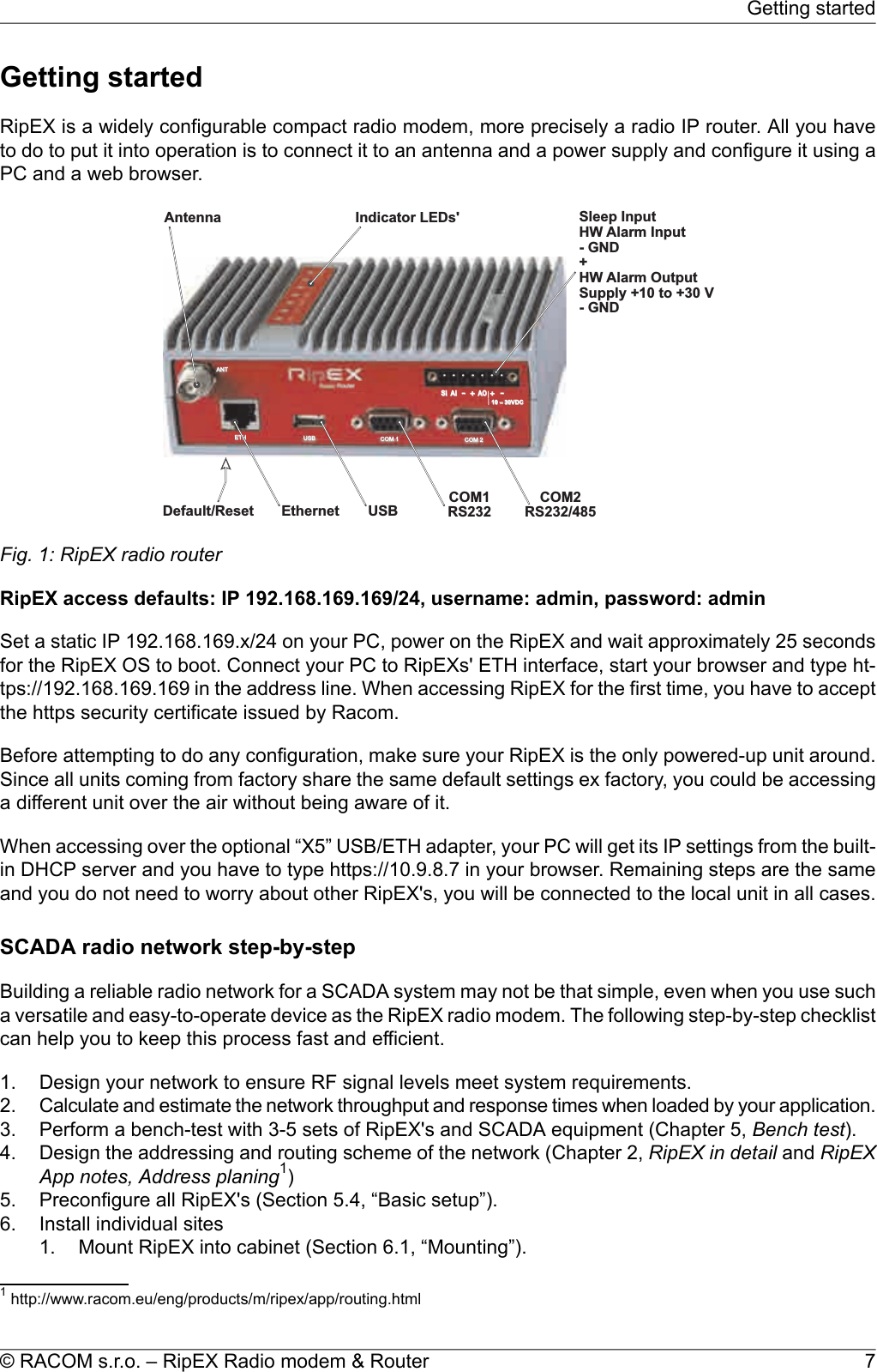
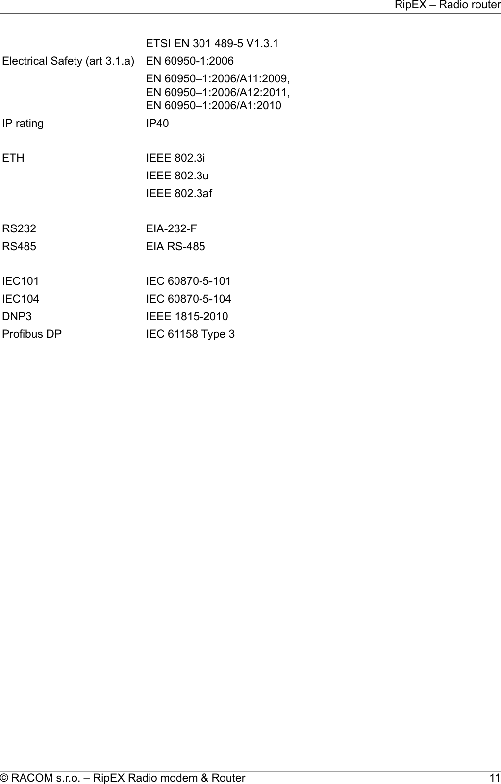
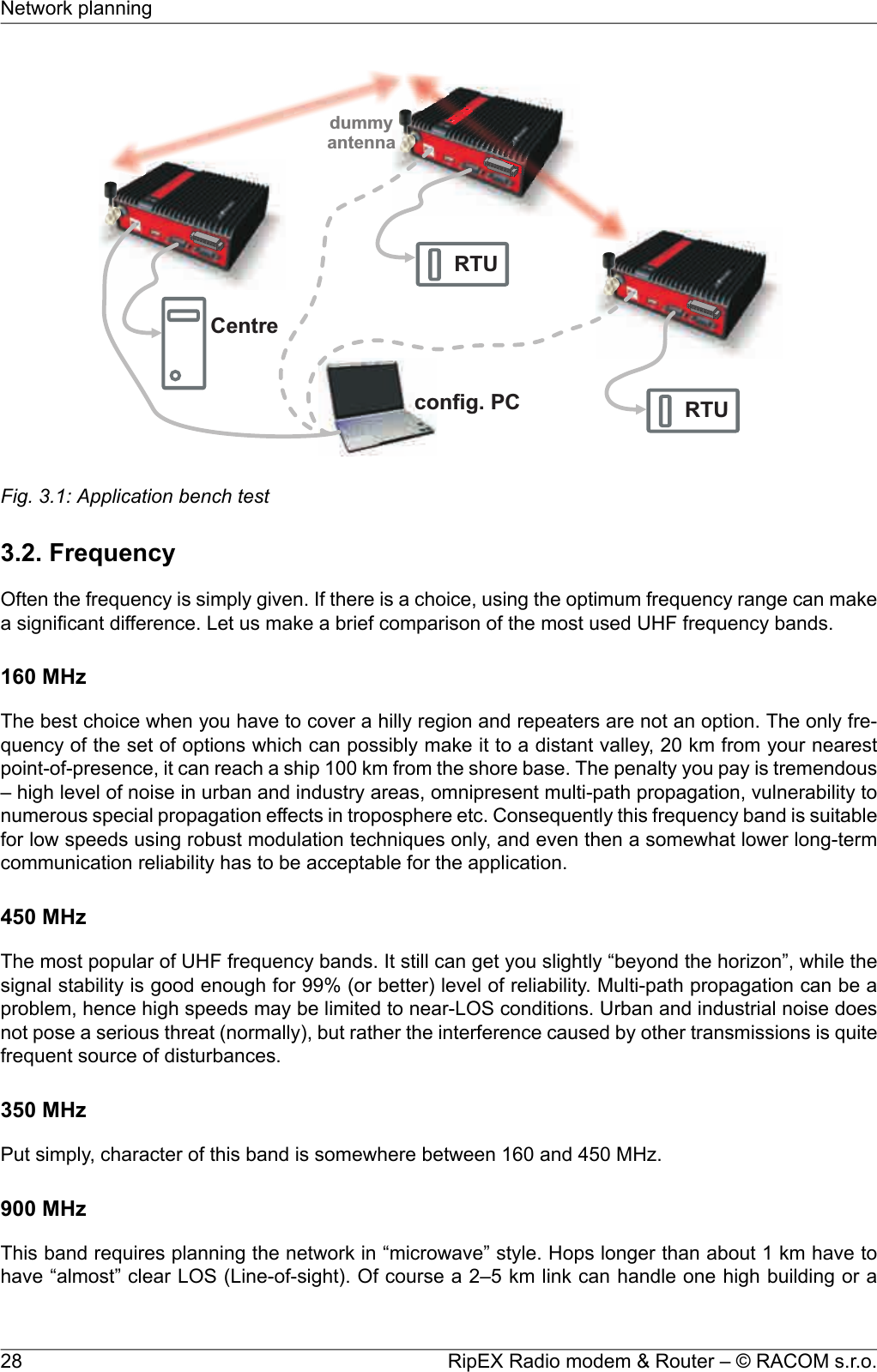
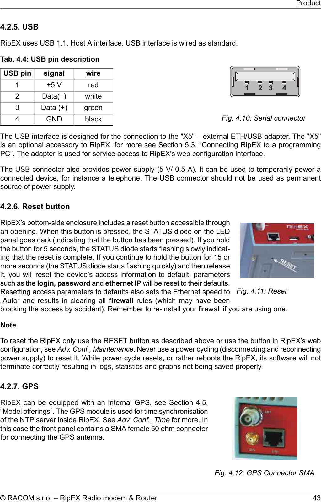
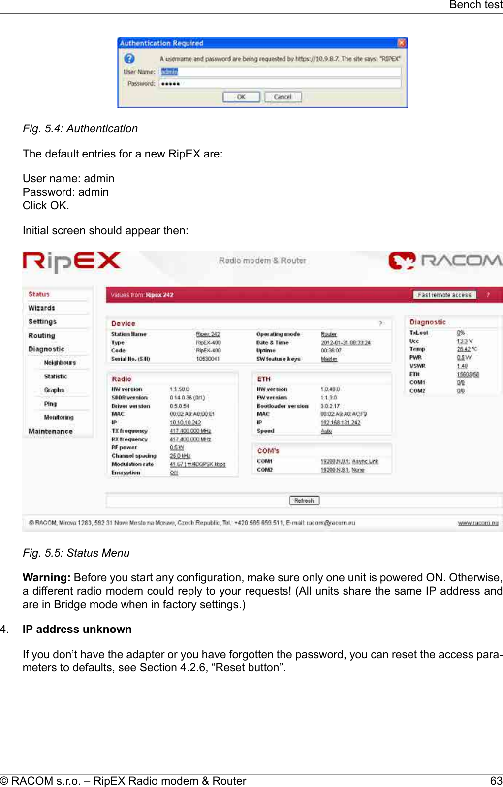
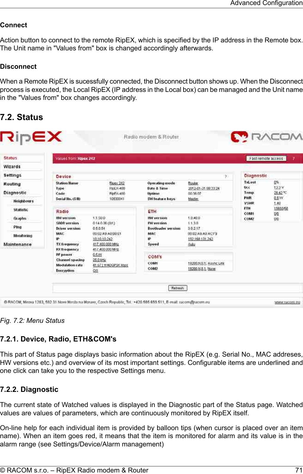
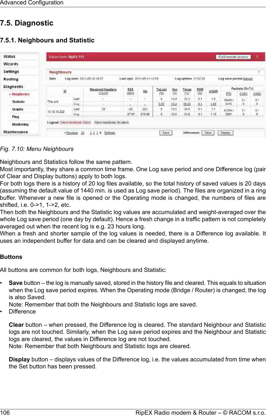
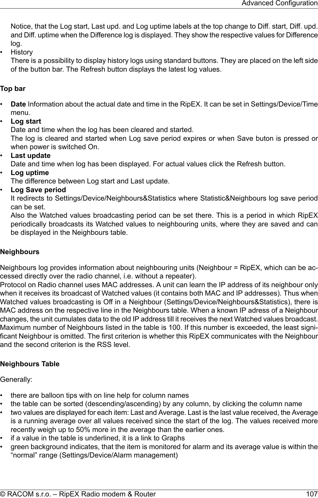
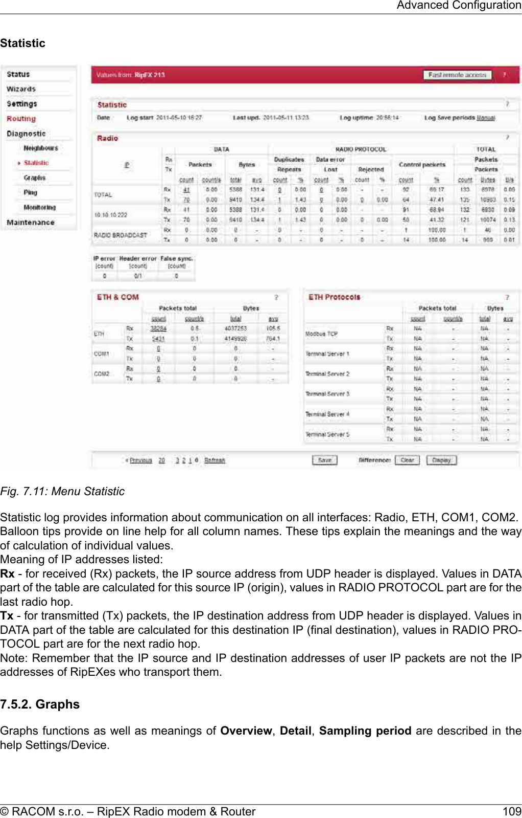
![2.6.1. LogsThere are ‘Neighbours’ and Statistic logs in RipEX. For both logs there is a history of 20 log filesavailable, so the total history of saved values is 20 days (assuming the default value of 1440 min. isused as the Log save period).NeighboursThe ‘Neighbours’ log provides information about neighbouring units (RipEX’s which can be accesseddirectly over the radio channel, i.e. without a repeater). Every RipEX on the network regularly broadcastsits status, the set of so called “Watched values”: the probability of packet loss when transmitting dataover the radio channel, current supply voltage, internal temperature, measured RF output power, theVoltage Standing Wave Ratio on the antenna feed line and the total number of packets received from/ transmitted to ETH, COM1, COM2 interfaces. In addition, the RipEX that records this data in its logalso keeps track of how many times it listened to its neighbouring unit as well as of the RSS and DQrecorded. See Adv. Conf., Diagnostic for more.StatisticThe ‘Statistic’ log provides information about the volume of data traffic on all interfaces: radio, ETH,COM1, COM2. It offers detailed information about the number of transmitted packets, their size andthe throughput per second. Moreover, a detailed division into user and service packets is available forthe radio channel. See chapter Adv. Conf., Diagnostic for more.2.6.2. GraphsAn independent database periodically stores the Watched values (see 'Neighbours' log above) fromup to five neighbouring RipEX's and from the local one, there including most important values from theStatistic log. All these values can be displayed as graphs.The graphs are available in summary and detailed versions. Detailed logging is triggered on when athreshold value has been reached for the specific item to enable a more detailed investigation into theunits’ operation when an alarm event occurs. Each graph can display two different elements at once,including their set thresholds. Each of the values may originate from a different RipEX unit.See chapter Adv. Conf., Graphs for more.2.6.3. SNMPRipEX implements an SNMP client ver. 1. The values provided by RipEX are shown in the MIB table.RipEX also allows generating SNMP traps when thresholds have been reached for the monitored values:RSScom, DQcom, TXLost[%], Ucc, Temp, PWR, VSWR, ETH[Rx/Tx], COM1[Rx/Tx], COM2[Rx/Tx],HW Alarm Input.See chapter RipEX App notes, SNMP for RACOM RipEX1for more.2.6.4. PingTo diagnose the individual radio links RipEX is equipped with an enhanced Ping tool. In addition to thestandard info such as the number of sent and received packets or the round trip time, it provides the1http://www.racom.eu/eng/products/m/ripex/app/snmp.htmlRipEX Radio modem & Router – © RACOM s.r.o.24RipEX in detail](https://usermanual.wiki/Racom/RIPEX-154/User-Guide-1865807-Page-24.png)
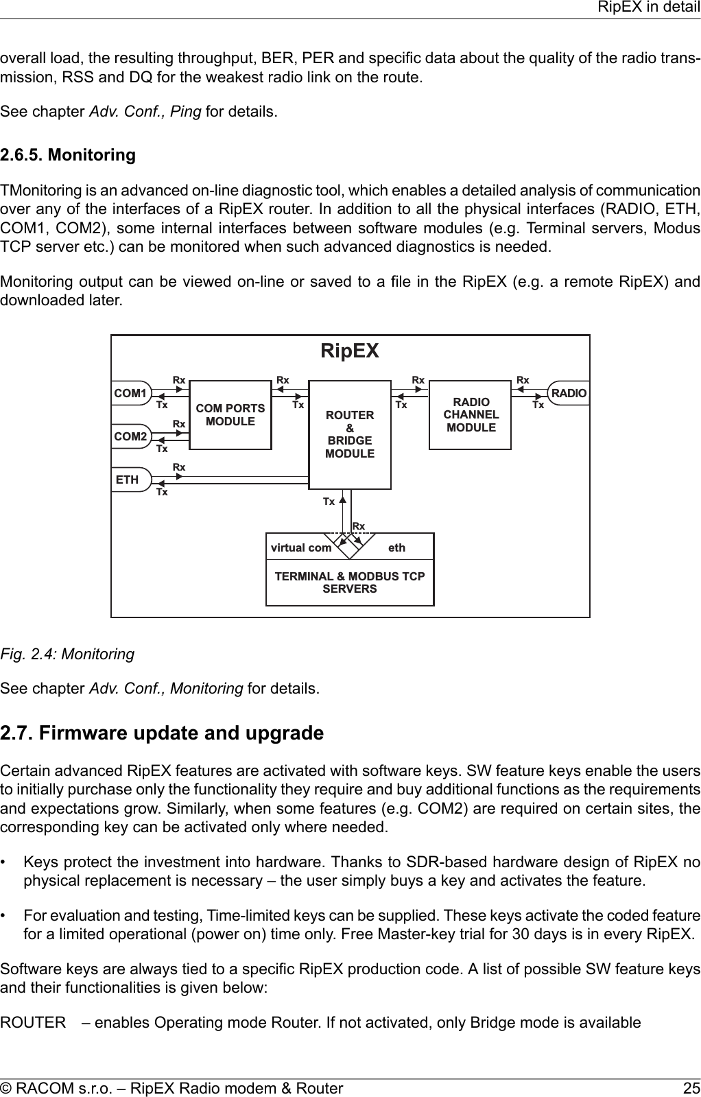
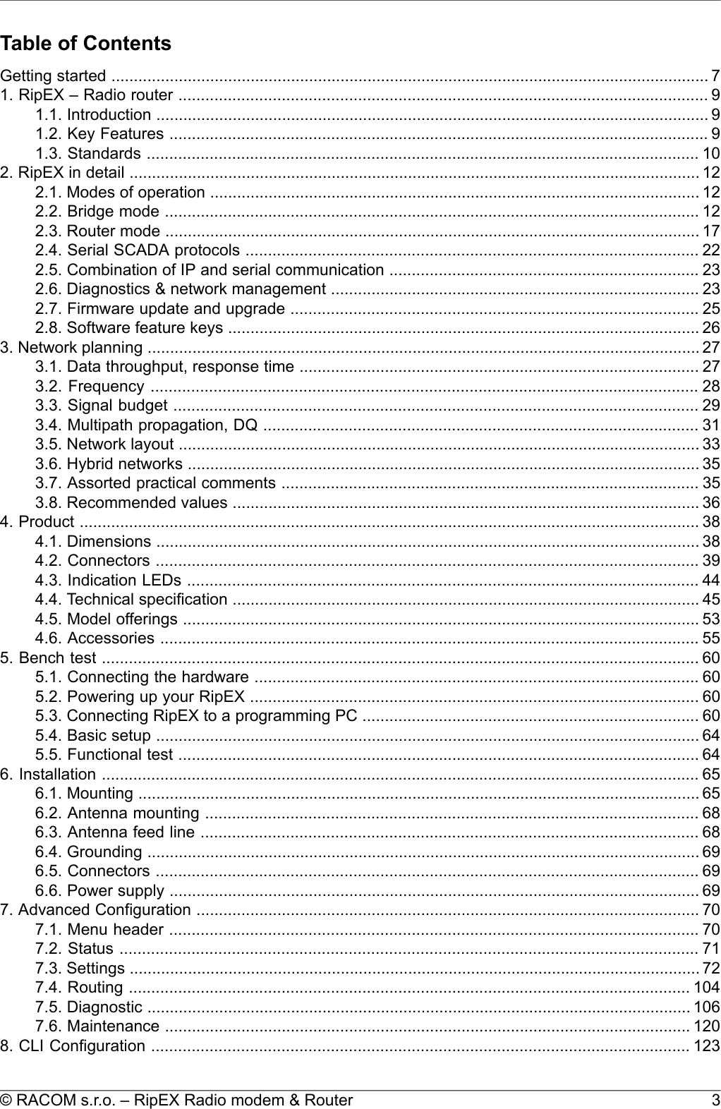
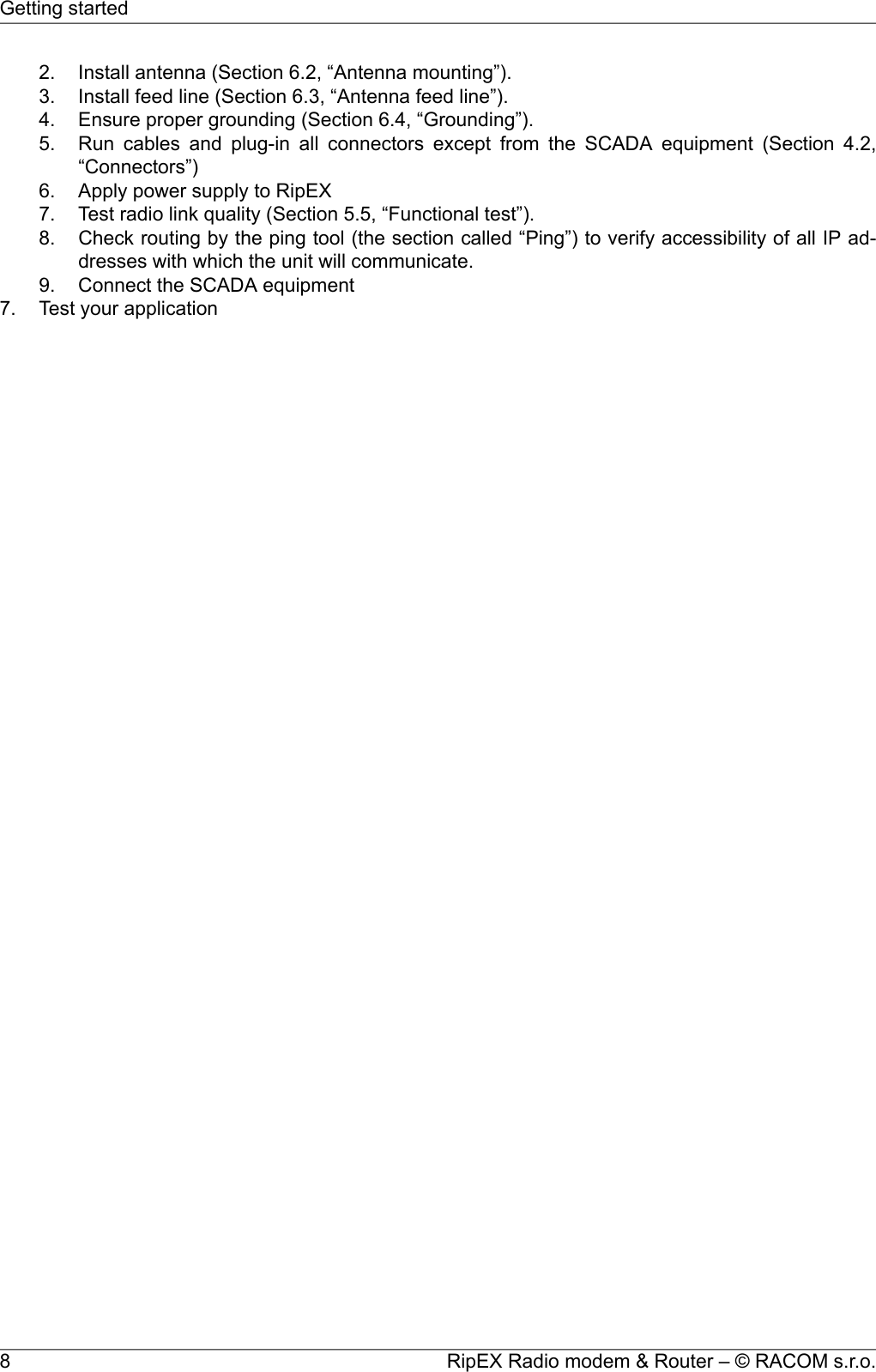
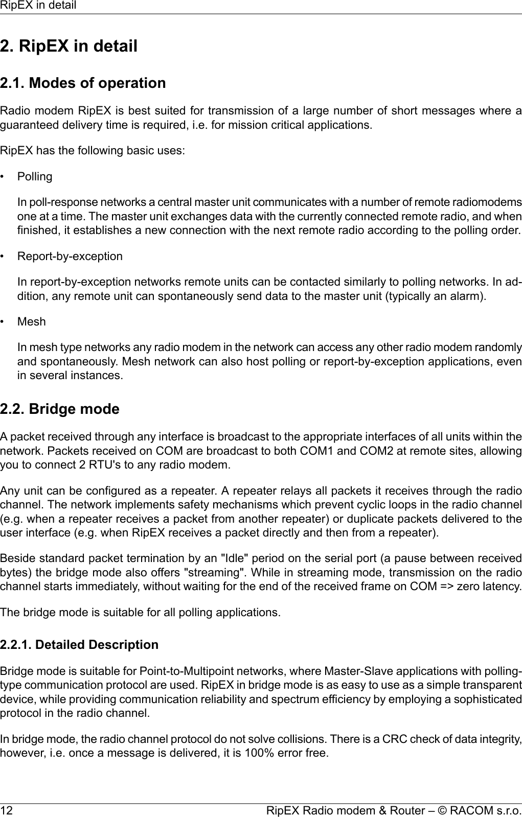
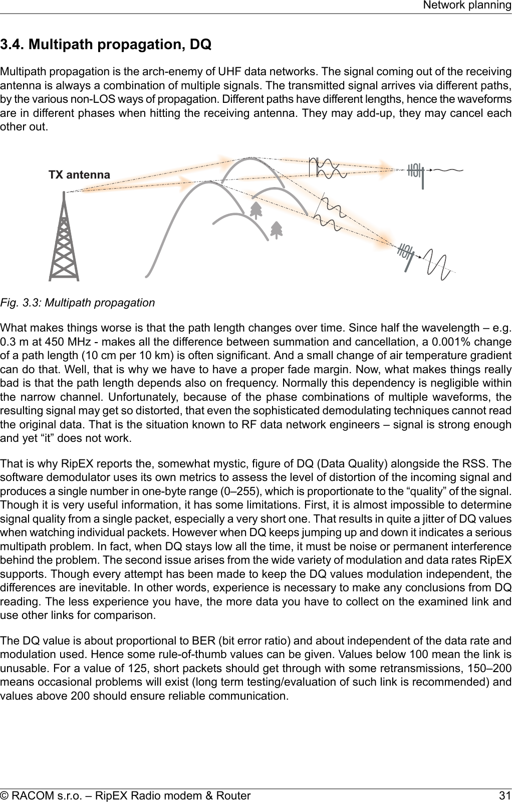
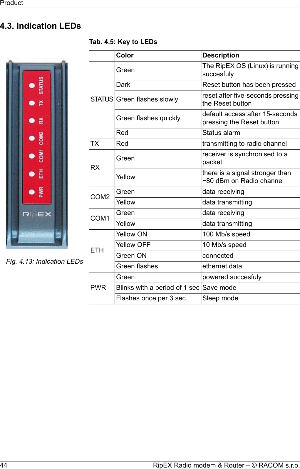
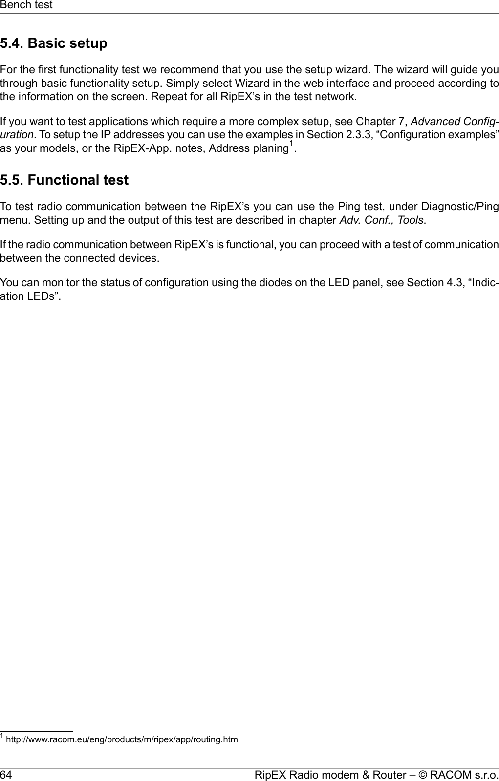
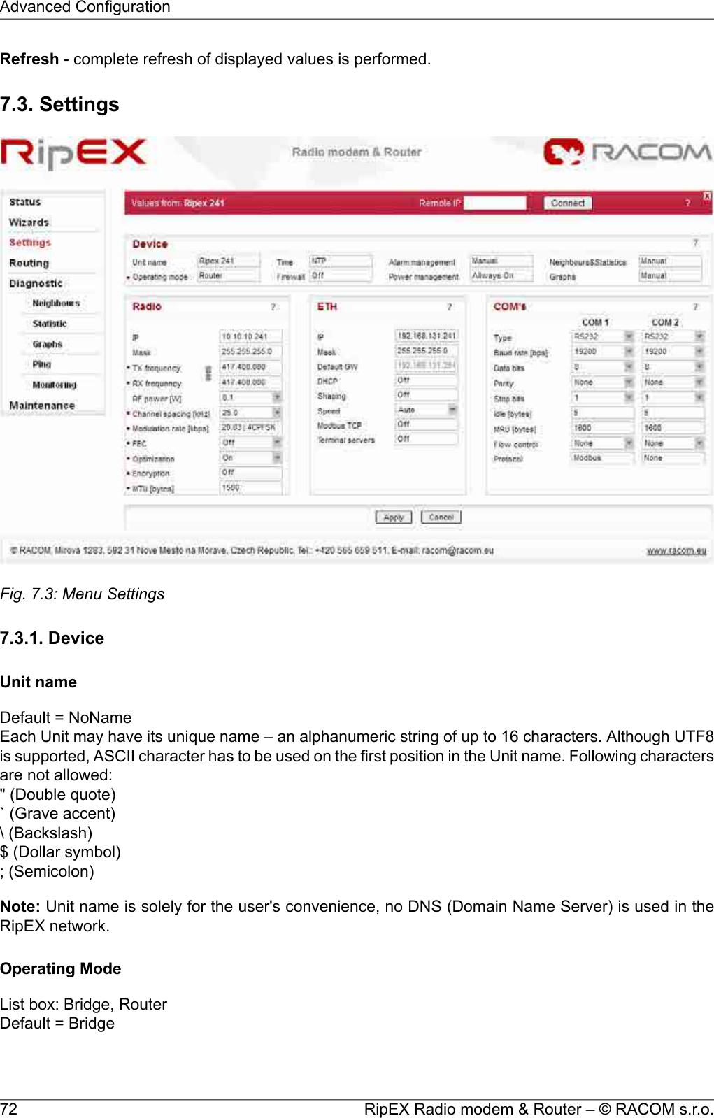
![bunch of trees in the middle, (which would be a fatal problem for e.g. an 11 GHz microwave). 900 MHzalso penetrates buildings quite well, in an industrial environment full of steel and concrete it may bethe best choice. The signal gets “everywhere” thanks to many reflections, unfortunately there is badnews attached to this - the reliability of high speed links in such environment is once again limited.Otherwise, if network capacity is your main problem, then 900 MHz allows you to build the fastest andmost reliable links. The price you pay (compared to lower frequency bands) is really the price – morerepeaters and higher towers increase the initial cost. Long term reliable performance is the reward.The three frequency bands discussed illustrate the simple basic rules – the higher the frequency, thecloser to LOS the signal has to travel. That limits the distance over the Earth's surface – there is noother fundamental reason why shorter wavelengths could not be used for long distance communication.On the other hand, the higher the frequency, the more reliable the radio link is. The conclusion is thenvery simple – use the highest frequency band you can.3.3. Signal budgetFor every radio hop which may be used in the network, the signal level at the respective receiver inputhas to be calculated and assessed against requirements. The fundamental requirements are two – thedata rate, which is dictated by total throughput and response times required by the application, and theavailability, which is again derived from the required reliability of the application. The data rate translatesto receiver sensitivity and the availability (e.g. 99,9 % percent of time) results in size of the fade margin.The basic rule of signal budget says, that the difference between the signal level at the receiver inputand the guaranteed receiver sensitivity for the given data rate has to be greater than the fade marginrequired:RX signal [dBm] – RX sensitivity [dBm] >= Fade margin [dB]To calculate the RX signal level, we follow the RF signal path:TXoutputRXinputfeedlinelossfeedlinelosspathlossTXantennagainRXantennagain+ +Fig. 3.2: Signal pathexample:RX signal [dBm] =dBm (TX output 1 W)+30.0+ TX output [dBm]dB (20m cable RG-213 U, 400 MHz)-2.5- TX antenna feeder loss [dB]dBi (half-wave dipole, 0 dBd)+2.1+TX antenna gain [dBi]dB calculated from field measurement)-125.0- Path loss [dB]dB (7-al Yagi antenna, 7.6 dBd)+9.7+ RX antenna gain [dBi]29© RACOM s.r.o. – RipEX Radio modem & RouterNetwork planning](https://usermanual.wiki/Racom/RIPEX-154/User-Guide-1865807-Page-29.png)
![dB (10 m cable RG-58 CU, 400 MHz)-3.1- RX antenna feeder loss [dB]dBm Received Signal Strength (RSS)= -88.8The available TX output power and guaranteed RX sensitivity level for the given data rate have to bedeclared by the radio manufacturer. RipEX values can be found in Table 4.6, “Technical parameters”and Chap Section 4.4.1, “Detailed Radio parameters”. Antenna gains and directivity diagrams have tobe supplied by the antenna manufacturer. Note that antenna gains against isotropic radiator (dBi)are used in the calculation. The figures of feeder cable loss per meter should be also known. Note thatcoaxial cable parameters may change considerably with time, especially when exposed to an outdoorenvironment. It is recommended to add a 50-100 % margin for ageing to the calculated feeder loss.3.3.1. Path loss and fade marginThe path loss is the key element in the signal budget. Not only does it form the bulk of the total loss,the time variations of path loss are the reason why a fade margin has to be added. In reality, very oftenthe fade margin is the single technical figure which expresses the trade-off between cost and perform-ance of the network. The decision to incorporate a particular long radio hop in a network, despite thatits fade margin indicates 90 % availability at best, is sometimes dictated by the lack of investment in ahigher tower or another repeater. Note that RipEXs Auto-speed feature allows the use of a lower datarate over specific hops in the network, without the need to reduce the rate and consequently thethroughput in the whole network. Lower data rate means lower (= better) value of receiver sensitivity,hence the fade margin of the respective hop improves. See the respective Application note to learnmore on the Auto-speed feature.When the signal path profile allows for LOS between the TX and RX antennas, the standard formulafor free-space signal loss (below) gives reliable results:Path loss [dB] = 20 * log10 (distance [km]) + 20 * log10 (frequency [MHz]) + 32.5In the real world the path loss is always greater. UHF radio waves can penetrate obstacles (buildings,vegetation), can be reflected from flat objects, can bend over round objects, can disperse behind sharpedges – there are numerous ways how a radio signal can propagate in non-LOS conditions. The addi-tional loss when these propagation modes are involved (mostly combined) is very difficult to calculate.There are sophisticated methods used in RF design software tools which can calculate the path lossand its variations (statistical properties) over a computer model of terrain. Their accuracy is unfortunatelyvery limited. The more obstacles on the path, the less reliable is the result. Such a tool can be veryuseful in the initial phase of network planning, e.g. to do the first network layout for the estimate of totalthroughput, however field measurements of every non-LOS radio hop should be done before the finalnetwork layout is designed.Determining the fade margin value is even more difficult. Nevertheless the software tools mentionedcan give some guidance, since they can calculate the statistical properties of the signal. Generally thefade margin (for given availability) is proportional to the difference between the real path loss and theLOS path loss over the same distance. Then it is about inversely proportional to frequency (in the UHFrange at least). To give an example for 10 km, non-LOS, hop on 450 MHz, fade margin of 20 dB is abare minimum. A field test may help again, provided it is run for longer period of time (hours-days).RipEX diagnostic tools (ping) report the mean deviation of the RSS, which is a good indication of thesignal stability. A multiple of the mean deviation should be added to the fade margin.RipEX Radio modem & Router – © RACOM s.r.o.30Network planning](https://usermanual.wiki/Racom/RIPEX-154/User-Guide-1865807-Page-30.png)
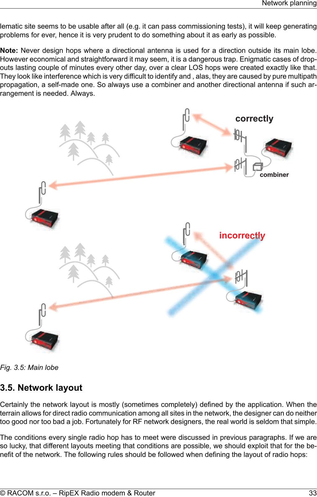
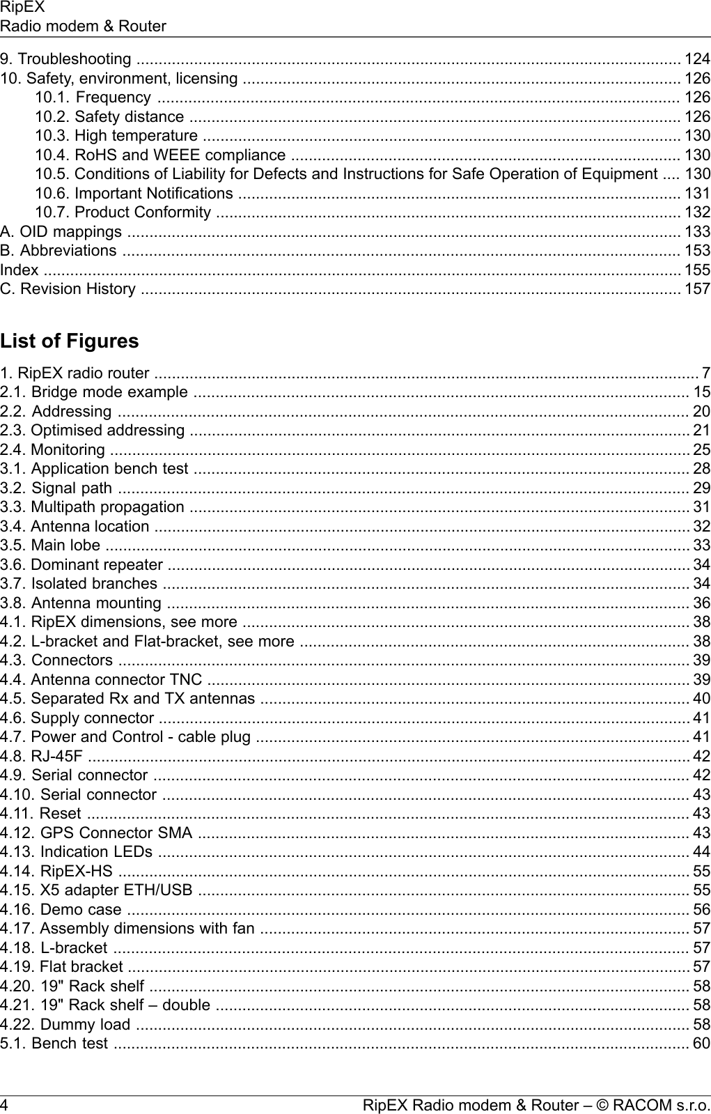
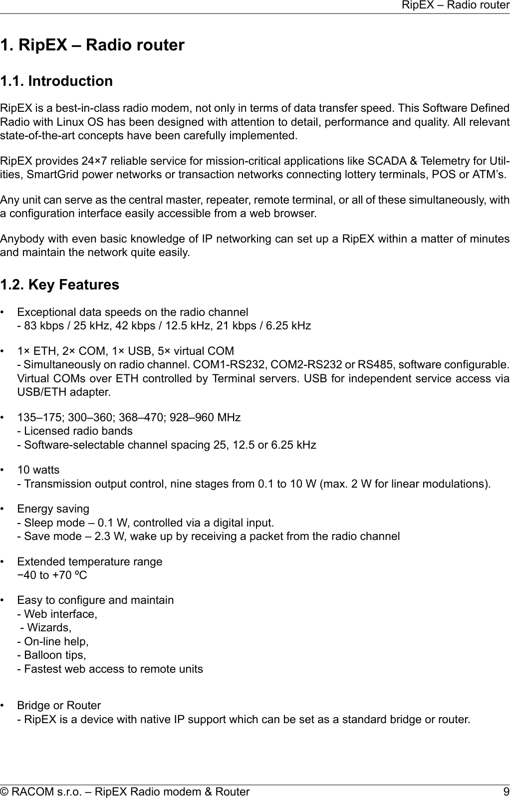
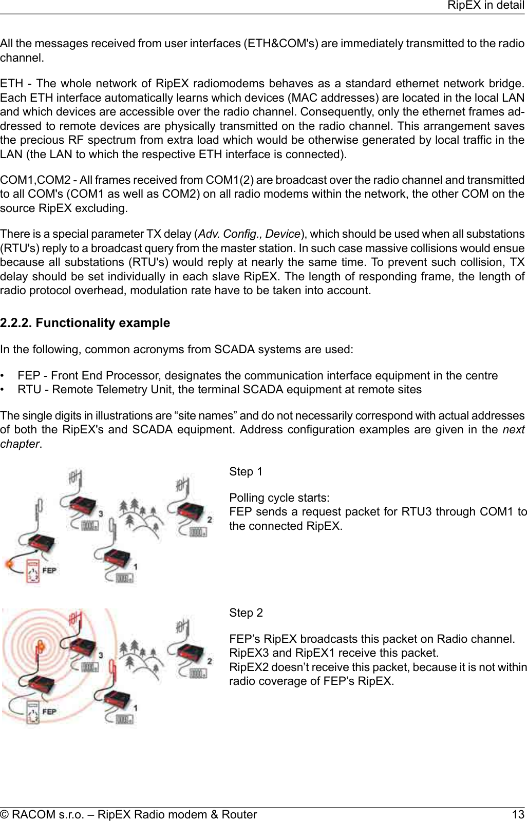
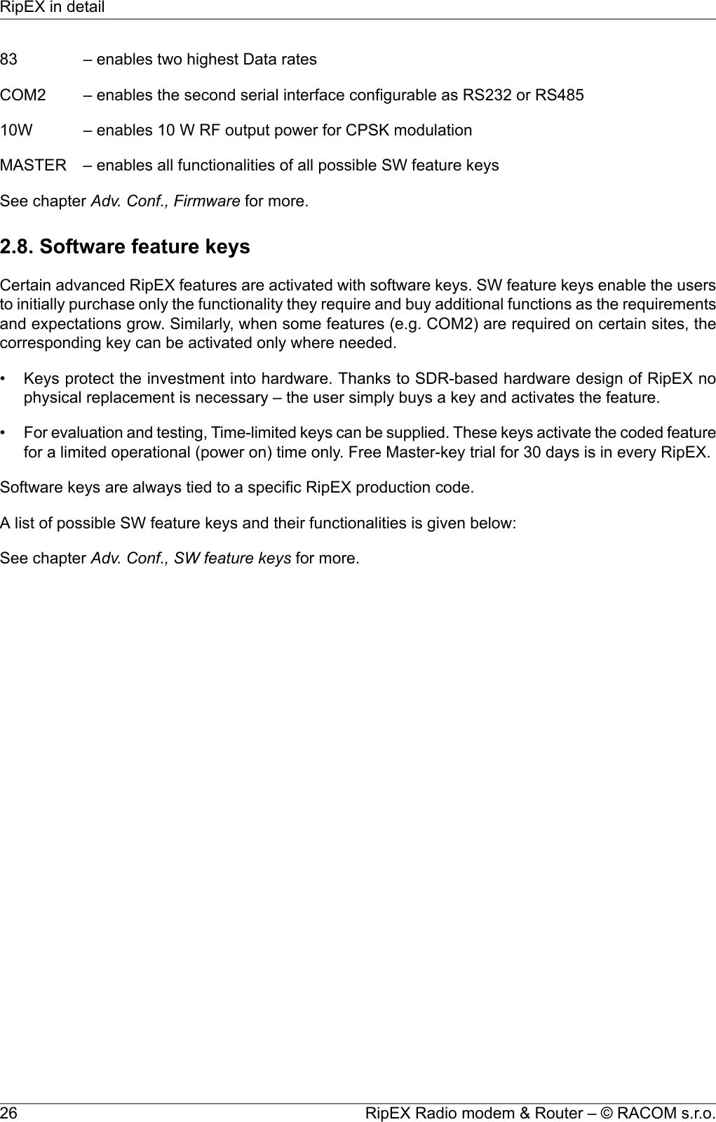
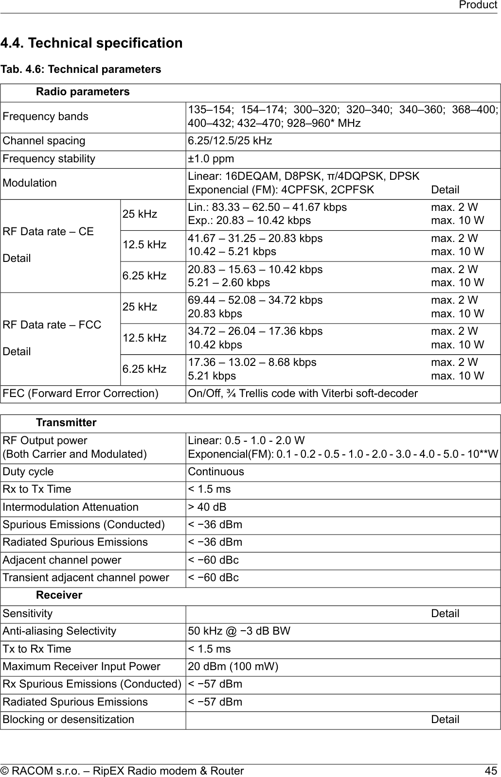
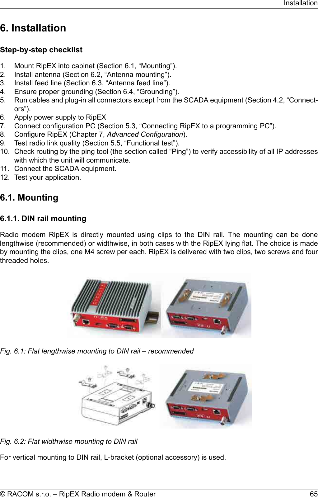
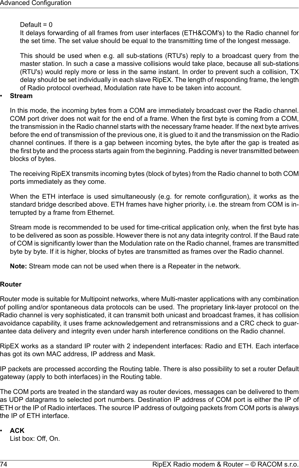
![generated noise. The ground plane forms an integral part of such an antenna, hence it has to bein a safe distance (several metres) from any electronic equipment as well as the antenna itself. Ametallic plate used as shielding against interference must not form a part of the antenna.incorectly correctlyPowersupplyRTUFig. 3.8: Antenna mounting• Do not underestimate ageing of coaxial cables, especially at higher frequencies. Designing a 900MHz site with 30 m long antenna cable run outdoors would certainly result in trouble two years later.• We recommend to use vertical polarization for all radio modem networks.3.8. Recommended valuesTo check individual radio link quality run Ping test with these settings: Ping type - RSS, Length [bytes]equal to the longest packets in the networks. Use Operating mode Bridge, when Router, ACK set toOff. Switch off all other traffic on the Radio channel used for testing. The test should run at least hours,preferrably day(s). The values below should guarantee a reliable radio link:•Fade marginMin. 20 dBFade margin [dB] = RSS (Received Signal Strenght) [dBm] – RX sensitivity [dBm].Respective RX sensitivity for different data rates can be found in Section 4.4.1, “Detailed Radioparameters”.RipEX Radio modem & Router – © RACOM s.r.o.36Network planning](https://usermanual.wiki/Racom/RIPEX-154/User-Guide-1865807-Page-36.png)
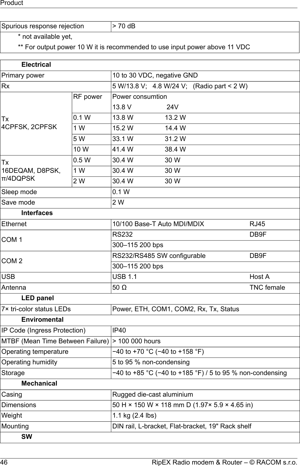
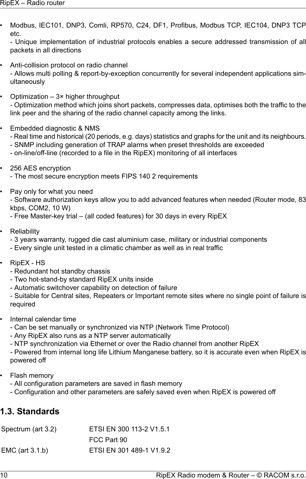
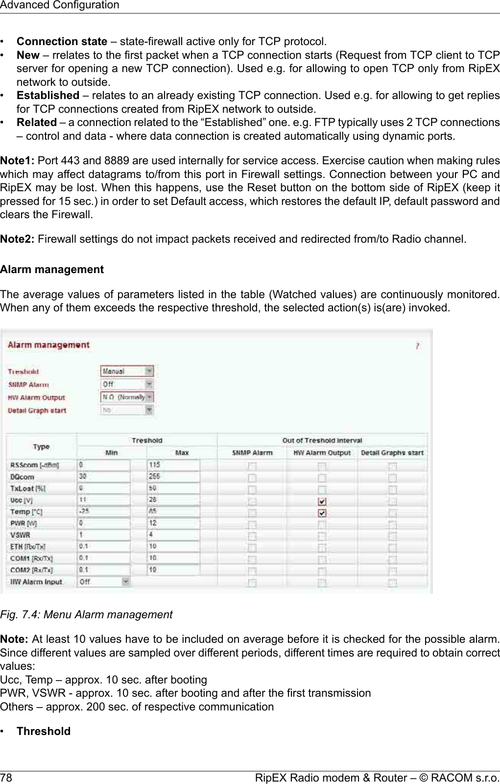
![Bridge / RouterOperating modesModbus, IEC101, DNP3, UNI, Comli, DF1, RP570, Profibus…User protocols on COMModbus TCP, IEC104, DNP3 TCP, Comli TCP Terminal server…User protocols on EthernetModbus RTU / Modbus TCP, DNP3 / DNP3 TCPSerial to IP convertorsProtocol on Radio channelYesMulti master applicationsYesReport by exceptionYesCollision Avoidance CapabilityYesRemote to Remote communicationYesAddressed & acknowledged serialSCADA protocolsCRC 32Data integrity controlAES256Encryptionup to 3× higher throughputOptimizationDiagnostic and ManagementYes (ping with RSS, Data Quality, Homogenity)Radio link testingDevice – Ucc, Temp, PWR, VSWR, *HW Alarm Input.Radio channel – *RSScom, *DQcom, TXLost[%]User interfaces – ETH[Rx/Tx], COM1[Rx/Tx], COM2[Rx/Tx]* not broadcastWatched values (Can be broadcastto neighbouring units. Received infodisplayed in Neighbours table)For Rx/Tx Packets on User interfaces (ETH, COM1, COM2) andfor User data and Radio protocol (Repeates, Lost, ACK etc.) onRadio channelStatisticsFor Watched values and StatisticsGraphs20 periods (configurable, e.g. days)History (Statistics, Neighbours,Graphs)SNMPv1, SNMPv2Trap alarms generation for Watched valuesSNMPReal time/Save to file analysis of all physical interfaces (RADIO,ETH, COM1, COM2) and some internal interfaces betweenMonitoring software modules (e.g. Terminal servers, Modus TCP serveretc.)StandardsCE, FCC, RoHSETSI EN 300 113-2 V1.5.1Spectrum (art 3.2)FCC Part 90ETSI EN 301 489-1 V1.9.2EMC (electromagnetic compatibility)(art 3.1.b) ETSI EN 301 489-5 V1.3.1EN 60950-1:2006Safety (art 3.1.a)EN 60950–1:2006/A11:2009,EN 60950–1:2006/A12:2011,EN 60950–1:2006/A1:201047© RACOM s.r.o. – RipEX Radio modem & RouterProduct](https://usermanual.wiki/Racom/RIPEX-154/User-Guide-1865807-Page-47.png)
![4.4.1. Detailed Radio parametersThe very first parameter which is often required for consideration is the receiver sensitivity. Anyoneinterested in the wireless data transmission probably aware what this parameter means, but we shouldregard it simultaneously in its relation to other receiver parameters, especially blocking and desensitiz-ation. Today’s wireless communication arena tends to be overcrowded and a modern radio modem,which is demanded to compete with others in that environment, should have good dynamic range thatis defined by the parameters listed above. Receiver of a radio modem, which is designed purely foroptimum sensitivity, will not be able to give proper performance. However, the main receiver parametersdetermining its dynamic range go against each other and a clear trade-off between the sensitivity andthe blocking is therefore an essential assumption. Then, from the viewpoint of a logical comparison,the consequence of better receiver sensitivity can be easily seen – a lower power level of the blockingand degradation parameters generally.Blocking or desensitization values were determined according to the standards EN 300 113-2 V1.5.1,resp. EN 300 113-1 V1.7.1 (channels 25 and 12.5 kHz) and ETSI 301 166-1 V1.3.2 (channel 6.25 kHz)respectively.Tab. 4.8: CE 25 kHzCE 25 kHzBlocking ordesensitization [dBm]Sensitivity [dBm]Classification±10 MHz±5 MHz±1 MHzBER 10-6BER 10-3BER 10-2EmissionModulationFECkbps-5-6-8-111-115-11813K8F1DCN2CPFSK0.757.81-7-8-10-110-114-11713K8F1DBN2CPFSK1.0010.42-7-9-9-107-112-11514K2F1DDN4CPFSK0.7515.63-9-11-11-104-110-11314K2F1DDN4CPFSK1.0020.83-5-6-6-107-112-11424K0G1DCNDPSK0.7515.62-7-8-8-106-111-11324K0G1DBNDPSK1.0020.83-3-4-4-106-110-11324K0G1DDNπ/4-DQPSK0.7531.25-5-6-6-104-108-11124K0G1DDNπ/4-DQPSK1.0041.66-8-8-8-98-103-10624K0G1DEND8PSK0.7546.87-9.5-10-10-95-101-10424K0G1DEND8PSK1.0062.49-5-6-6-95-101-10424K0D1DEN16DEQAM0.7562.49-7-8-8-93-99-10224K0D1DEN16DEQAM1.0083.3249© RACOM s.r.o. – RipEX Radio modem & RouterProduct](https://usermanual.wiki/Racom/RIPEX-154/User-Guide-1865807-Page-49.png)
![Tab. 4.9: CE 12.5 kHzCE 12.5 kHzBlocking ordesensitization [dBm]Sensitivity [dBm]Classification±10 MHz±5 MHz±1 MHzBER 10-6BER 10-3BER 10-2EmissionModulationFECkbps-3-4-6-113-117-1207K00F1DCN2CPFSK0.753.91-5-6-8-112-116-1197K00F1DBN2CPFSK1.005.21-5-6-6-108-114-1177K00F1DDN4CPFSK0.757.81-7-8-8-105-112-1157K00F1DDN4CPFSK1.0010.42-3-4-4-110-114-11611K9G1DCNDPSK0.757.81-5-6-6-109-113-11511K9G1DBNDPSK1.0010.42-2-3-3.5-109-113-11511K9G1DDNπ/4-DQPSK0.7515.62-3-4-4-106-111-11411K9G1DDNπ/4-DQPSK1.0020.83-5-6-6-101-106-10911K9G1DEND8PSK0.7523.44-7-8-8-98-104-10711K9G1DEND8PSK1.0031.25-2-3-3-99-104-10711K9D1DEN16DEQAM0.7531.25-4-5-5-96-102-10511K9D1DEN16DEQAM1.0041.67Tab. 4.10: CE 6.25 kHzCE 6.25 kHzBlocking ordesensitization [dBm]Sensitivity [dBm]Classification±10 MHz±5 MHz±1 MHzBER 10-6BER 10-3BER 10-2EmissionModulationFECkbps+5.5+1.0-0.5-114-120-1223K00F1DCN2CPFSK0.751.96+4.0-1.0-2.5-113-119-1213K00F1DBN2CPFSK1.002.61+5.0-0.0-1.5-111-116-1193K00F1DDN4CPFSK0.753.91+3.0-1.5-3.5-108-114-1173K00F1DDN4CPFSK1.005.217.01.50.0-113-118-1216K0G1DDPSK0.753.915.0-0.5-2.0-112-117-1196K0G1DDPSK1.005.216.03.0+1.0-112-115-1176K0G1Dπ/4-DQPSK0.757.824.01.0-0.5-110-113-1166K0G1Dπ/4-DQPSK1.0010.424.01.0-1.0-104-109-1116K0G1DD8PSK0.7511.722.0-1.0-3.0-104-109-1116K0G1DD8PSK1.0015.631.5-2.0-7.5-103-107-1106K0D1D16DEQAM0.7515.630.0-3.5-5.5-99-104-1076K0D1D16DEQAM1.0020.83RipEX Radio modem & Router – © RACOM s.r.o.50Product](https://usermanual.wiki/Racom/RIPEX-154/User-Guide-1865807-Page-50.png)
![Tab. 4.11: FCC 25 kHzFCC 25 kHzBlocking ordesensitization [dBm]Sensitivity [dBm]Classification±10 MHz±5 MHz±1 MHzBER 10-6BER 10-3BER 10-2EmissionModulationFECkbps-0.0-1.0-3.5-108-113-11618K6F1DDN4CPFSK0.7515.63+1.5-2.5-5.0-105-111-11418K6F1DDN4CPFSK1.0020.83-0.5-2.0-4.5-107-111-11419K8G1DDNπ/4-DQPSK0.7526.04-2.0-4.0-6.5-105-109-11219K8G1DDNπ/4-DQPSK1.0034.72-5.5-7.0-9.0-99-105-10819K8G1DEND8PSK0.7539.06-7.5-9.0-11-96-103-10619K8G1DEND8PSK1.0052.08-8.0-9.0-12-96-103-10619K8D1DEN16DEQAM0.7552.08-10-12-14-94-101-10419K8D1DEN16DEQAM1.0069.44Tab. 4.12: FCC 12.5 kHzFCC 12.5 kHzBlocking ordesensitization [dBm]Sensitivity [dBm]Classification±10 MHz±5 MHz±1 MHzBER 10-6BER 10-3BER 10-2EmissionModulationFECkbps-4-5-5-108-114-1178K90F1D4CPFSK0.757.81-6-7-7-105-112-1158K90F1D4CPFSK1.0010.42-2-2-2-109-113-11510K0G1Dπ/4-DQPSK0.7513.02-3-4-4-106-111-11410K0G1Dπ/4-DQPSK1.0017.36-5-6-6-101-106-10910K0G1DD8PSK0.7519.53-7-8-8-98-104-10710K0G1DD8PSK1.0026.04-2-3-3-99-104-10710K0D1D16DEQAM0.7526.04-4-5-5-96-102-10510K0D1D16DEQAM1.0034.72Tab. 4.13: FCC 6.25 kHzFCC 6.25 kHzBlocking ordesensitization [dBm]Sensitivity [dBm]Classification±10 MHz±5 MHz±1 MHzBER 10-6BER 10-3BER 10-2EmissionModulationFECkbps-2-2-2-112-117-1204K35F1D4CPFSK0.753.91-3-4-4-109-115-1184K35F1D4CPFSK1.005.21-2-3-3-113-116-1185K00G1Dπ/4-DQPSK0.756.51-4-5-5-111-114-1175K00G1Dπ/4-DQPSK1.008.68-2-2-2-105-110-1125K00G1DD8PSK0.759.77-3-4-4-102-107-1105K00G1DD8PSK1.0013.02-2-3-3-103-107-1105K00D1D16DEQAM0.7513.02-4-5-5-100-105-1085K00D1D16DEQAM1.0017.3651© RACOM s.r.o. – RipEX Radio modem & RouterProduct](https://usermanual.wiki/Racom/RIPEX-154/User-Guide-1865807-Page-51.png)
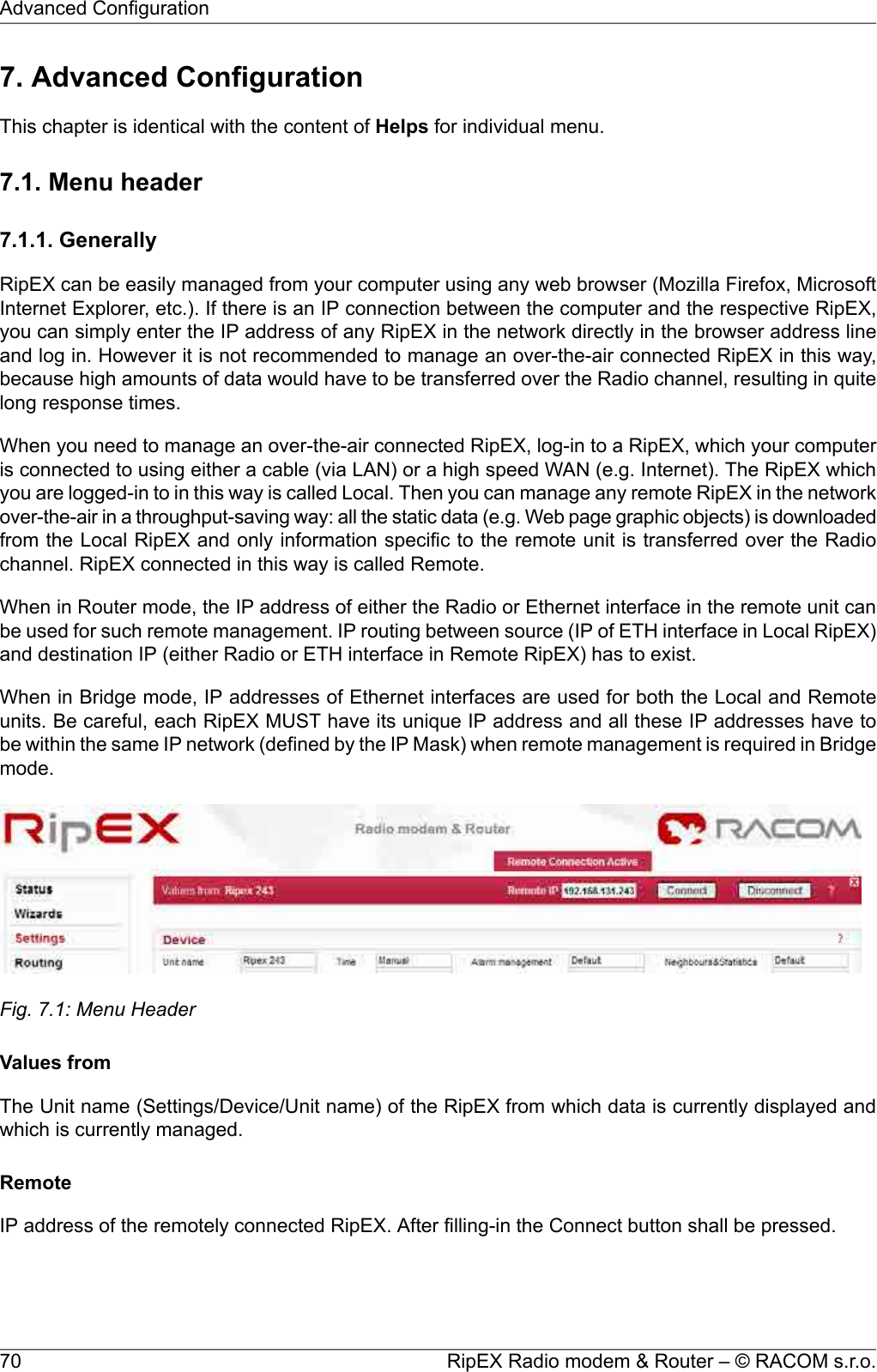
![BridgeBridge mode is suitable for Point-to-Multipoint networks, where Master-Slave application with polling-type communication protocol is used. RipEX in Bridge mode is as easy to use as a simple transparentdevice, while allowing for a reasonable level of communication reliability and spectrum efficiency insmall to medium size networks.poIn Bridge mode, the protocol on Radio channel does not have the collision avoidance capability. Thereis CRC check of data integrity, i.e. once a message is delivered, it is 100% error free.All the messages received from user interfaces (ETH&COM's) are immediately transmitted to Radiochannel, without any checking or processing.ETH: The whole network of RipEX units behaves like a standard Ethernet network bridge, so the Eth-ernet interface IP address itself is not significant. Each ETH interface automatically learns which devices(MAC addresses) lie in the local LAN and which devices are accessible via the Radio channel. Con-sequently only the Ethernet frames addressed to remote devices are physically transmitted on theRadio channel. This arrangement saves the precious RF spectrum from extra load which would otherwisebe generated by local traffic in the LAN (the LAN to which the respective ETH interface is connected).COM1,COM2: all frames received from COM1(2) are broadcast over Radio channel and transmittedto all COM's (COM1 as well as COM2) on all units within the network, the other COM on the sourceRipEX excluding.•Frame closing (COM1,2)List box: Idle, StreamDefault = Idle•IdleReceived frames on COM1 (COM2) are closed when gap between bytes is longer than the Idlevalue set in COM1,2 settings and transmitted to Radio channel afterwards.○RepeaterList box: Off, On.Default = OffEach RipEX may work simultaneously as a Repeater (Relay) in addition to the standard Bridgeoperation mode..If "On", every frame received from the Radio channel is transmitted to the respective user interface(ETH,COM1,2) and to the Radio channel again.The Bridge functionality is not affected, i.e. only frames whose recipients belong to the localLAN are transmitted from the ETH interface.It is possible to use more than one Repeater within a network. To eliminate the risk of creatinga loop, the "Number of repeaters" has to be set in all units in the network, including the Repeaterunits themselves.○Number of repeaters [0-7]Default = 0If there is a repeater (or more of them) in the network, the total number of repeaters within thenetwork MUST be set in all units in the network, including the Repeater units themselves. Aftertransmitting to or receiving from the Radio channel, further transmission (from this RipEX) isblocked for a period calculated to prevent collision with a frame transmitted by a Repeater.Furthemore, a copy of every frame transmitted to or received from the Radio channel is stored(for a period). Whenever a duplicate of a stored frame is received, it is discarded to avoid possiblelooping. These measures are not taken when the parameter "Number of repeaters" is zero, i.e.in a network without repeaters.○TX delay [ms] [0-5000]73© RACOM s.r.o. – RipEX Radio modem & RouterAdvanced Configuration](https://usermanual.wiki/Racom/RIPEX-154/User-Guide-1865807-Page-73.png)
![Default = On○OnEach frame transmitted on Radio channel from this RipEX has to be acknowledged by the re-ceiving RipEX, using the very short service packet (ACK), in order to indicate that it has receivedthe packet successfully. If ACK is not received, RipEX will retransmit the packet according itssetting of Retries.Note: The acknowledgement/retransmission scheme is an embedded part of the Radio protocoland works independently of any retries at higher protocol levels (e.g. TCP or user applicationprotocol)○OffThere is no requirement to receive ACK from the receiving RipEX. i.e. the packet is transmittedonly once and it is not repeated.•Retries [No] [0-15]Default = 3When an acknowledge from the receiving RipEX is not received, the frame is retransmitted. Thenumber of possible retries is specified.•RSS threshold [-dBm] [50-150]Default = 120RSS (Received Signal Strength) limit for access to Radio channel. RipEX does not start transmittingwhen a frame is being received and the RSS is better than the set limit or when the destinationMAC address of the frame is its own.•Repeat COM BroadcastList box: On, OffDefault = OffIf On, a broadcast originated on COM port (Protocol/Broadcast = On) in any remote unit and receivedby this unit on Radio channel is repeated to Radio channel.Hot StandbyWhen RipEX unit is used in RipEX-HS and Hot Standy is „On“ there are some limitations with it. Spe-cifically, CD pin on COM1 and HW alarm Input and Output are used internally and not available to theuser. Neither Save nor Sleep modes can be activated. Please refer RipEX-HS User manual.All settings below are valid only for RipEX units in RipEX-HS equipment, where two units in Hot Standbymode are running. Both units MUST have the same settings! Only Unit names should be different asthis parameter is used in SNMP to recognize the sender of SNMP traps. In order to ensure that thesettings of both units are identical, it is recommended to set unit “A”, thereafter save its settings into afile (Maintenance/Configuration/Save to file) and use these settings for unit “B”. (Maintenance/Config-uration/Restore/File path/Upload) Finally, a unique Unit name should be assigned to Unit B.List box: Off, OnDefault = OffWhen “On”, HW switching from RipEX unit “A” to RipEX unit “B” is performed based on the HW AlarmOutput settings in Settings/Alarm management. RipEX “A” is the primary unit, , Unit “B” is activated ifthere is HW alarm on unit “A” or unit “A” power source is down or when Auto Toggle Period expired.When mentioned events passed, RipEX “A” goes to be active again.•MACBoth units in RipEX-HS are using the same MAC addresses (MAC cloning). Whichever unit is active(either “A or B”), RipEX Ethernet interface will use this MAC address. This MAC address has to beunconditionally set to the same value in both units used in RipEX-HS. Otherwise, the switchingbetween units will not function properly.75© RACOM s.r.o. – RipEX Radio modem & RouterAdvanced Configuration](https://usermanual.wiki/Racom/RIPEX-154/User-Guide-1865807-Page-75.png)
![Read own – it is possible to download the MAC address of this unit. The value in the second unithas to be manually set to the same value then•Auto Toggle modeWhen Auto Toggle mode is On (HW button on front panel), controller automatically switches-overto RipEX ”B“, even if “A” doesn't have any alarm and uses “B” for a set time in order to confirm thatRipEX ”B“ is fully ready-to-operate.○Start Date [YYYY-MM-DD]Fill in the Date in the required format when Auto Toggle mode starts.○Start Time [HH:MM:SS]Fill in the Time in the required format when Auto Toggle mode starts on ”Start Date“ day.○Period [min.]Minimum value 60 min.Within this period units “A” and “B” will change their activities over. Unit “A” starts to operate at“Start Date and Time”. When “Period” minus “Unit B” time expires, controller switches to unit“B”.○Unit B [min.]Minimum value 5 min.Time when unit “B” will be active within “Period”. It has to be shorter than Period by 5 min.TimeList box: Manual, NTPDefault = ManualInternal calendar time of RipEX can be set manually or synchronized via NTP (Network Time Protocol).•ManualRipEX internally uses the Unix epoch time (or Unix time or POSIX time) - the number of secondsthat have elapsed since January 1, 1970. When RipEX calendar time is set, the Unix epoch timeis calculated based on filled in values (Date, Time) and the time zone, which is set in operatingsystem (computer), where the browser runs.○Current Date&TimeInformation about the actual date and time in the RipEX○Date [YYYY-MM-DD]Fill in Local Date in required format○Time [HH:MM:SS]Fill in Local Time in required format○RipEX Time zoneSelect RIPEX Time zone from list box.Default = (GMT +1:00) Central EuropeThis time zone is used for conversion of internal Unix epoch time to "human readable date&time"in RipEX logs.○Daylight savingList box: On, OffDefault = OnIf On, Daylight saving is activated according the respective rules for selected RipEX Time zone.•NTPRipEX Radio modem & Router – © RACOM s.r.o.76Advanced Configuration](https://usermanual.wiki/Racom/RIPEX-154/User-Guide-1865807-Page-76.png)
![Internal calendar time in RipEX is synchronized via NTP and RipEX also acts as a standard NTPserver simultaneously.○Current Date&TimeInformation about the actual date and time in RipEX○Time sourceList box: NTP server, Internal GPSDefault = NTP server■NTP server – The source of time is a standard NTP server. This server can be connectedeither via the Ethernet interface or over the Radio channel (any RipEX runs automatically asa NTP server).■Internal GPS – The source of time is the internal GPS. In this case only RipEX Time zoneand Daylight saving parameters below are active.○Source IPDefault = emptyIP address of the NTP server, which provides Time source. Date and Time will be requested byRipEX from there. More NTP servers can be configured, the more servers, the better time accur-acy. If the Time source is a RipEX over Radio channel, only one source server is recommended,since the Radio channel could be overloaded.○Minimum polling intervalList box: 1min to 2h 17minRipEX polls the source server in order to synchronize itself in the set period or later.○RipEX Time zoneSelect RipEX Time zone from list box.Default = (GMT +1:00) Central EuropeThis time zone is used for conversion of internal Unix epoch time to "human readable date&time"in RipEX logs..○Daylight savingList box: On, OffDefault = OnIf On, Daylight saving is activated according the respective rules for selected RipEX Time zone.•RipEX NTP serverInformation about the status of internal NTP server in the RipEX○State■ not synced - not synchronized■ synced to GPS - synchronized to internal GPS■ synced to NTP - synchronized to NTP server○Stratum1 to 16 (1=the best, 16=the worst, 8=when internal time in RipEX is set manually)The stratum represents the quality and accuracy of time, which the NTP server provides.○Delay [ms] This is the delay of packet (1/2 round trip time), which RipEX received from the NTPserver while asked for synchronization. This delay is compensated in the RipEX NTP server.○Jitter [ms]The Jitter of received times when RipEX asked for time synchronization from NTP server(s).FirewallList box: Off, OnDefault = OffThere is a standard Linux firewall implemente.•Port – a range of port numbers can be entered. E.g. 2000-2120.77© RACOM s.r.o. – RipEX Radio modem & RouterAdvanced Configuration](https://usermanual.wiki/Racom/RIPEX-154/User-Guide-1865807-Page-77.png)
![When On, RipEX remains on for the set seconds from the moment of its wake-up.○ Timeout from wake-up [sec.]Default = 300 [240 - 64 800]RipEX stays on for the set time from the moment of its wake-up.○ Reset timeout on received packetsList box: On, OffDefault = OffIf On, the Timeout from wake-up is reset with each packet received•Sleep ModeSleep Mode is controlled via the digital input on Power and Control connector. When the respectivepin is grounded, RipEX goes to sleep and consumes only 0.1 W at 13.8 V (see Section 4.4,“Technical specification”). The time needed for complete wake-up is approx. 25 seconds (bootingtime).○Timeout from sleep request [sec.]Default = 300 [0 - 64 800]RipEX remains on for the set time from the moment when the sleep input pin has been grounded.Neighbours&Statistics•ParametersList box: Default, Manual,Default = DefaultDefault – Default (recommended) values are set and can not be edited.Manual – Values can be set manually.There are 2 tables with diagnostic information in the main menu - Diagnostic/Neighbours, Diagnost-ic/Statistic. The Neighbours table displays Watched values from RipEX and from all its neighbours.(Neighbour = RipEX, which can be accessed directly over the radio channel, i.e. without a repeater).There is statistic information about the traffic volume in the Statistic table.○Watched values broadcasting period [min]Default = 10 min, [0 = Off]RipEX periodically broadcasts its Watched values to neighbouring units. The Watched valuescan be displayed in Graphs and Neighbours menu.Note: When Bridge mode is used, watched values broadcasting creates collisions for user traffic.Be careful in using this feature.○Neighbours&Statistic log save period [min]Default = 1440 min (1 day) [10 - 7200 min]This is the period, in which Neighbours and Statistics logs are saved in the archive and clearedand new logs start from the beginning.Note: The history files are organized in a ring buffer. Whenever a new file is opened, the numbersof files are shifted, i.e. 0->1, 1->2, etc. There is a history of 20 log files availableGraphs•ParametersList box: Default, Manual,Default = DefaultDefault – Default (recommended) values are set and can't be edited.Manual – Values can be set manually.Graphs displays history of Watched values and history of some of the items from the Statistic table.Displayed values are stored in each RipEX including data from selected five neighbouring units.Neighbour = RipEX, which can be accessed directly over the Radio channel (not over Ethernet),RipEX Radio modem & Router – © RACOM s.r.o.80Advanced Configuration](https://usermanual.wiki/Racom/RIPEX-154/User-Guide-1865807-Page-80.png)
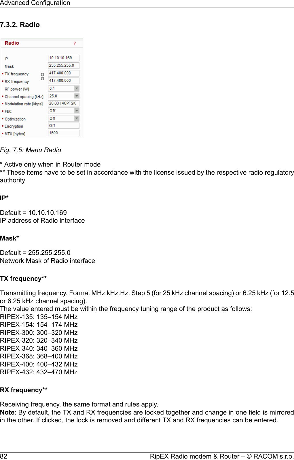
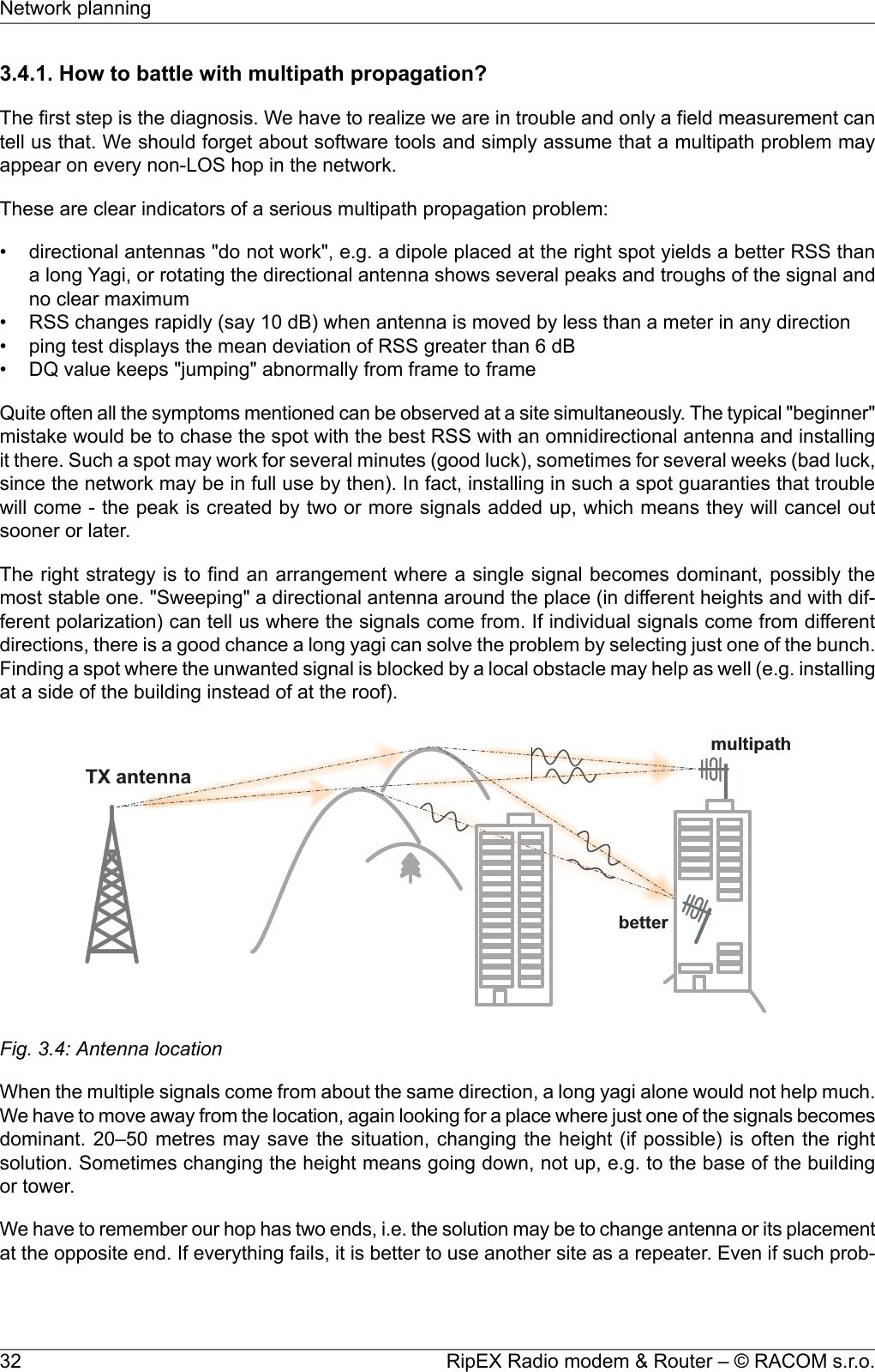
![RF power [W]**List box: possible valuesDefault = 5 WThe range of values in the list box is limited to 2 W for high Modulation rates. 10 W is available onlyfor lower Modulation rates (CPFSK) and only when the corresponding SW feature key is active.Channel spacing [kHz]**List box: possible valuesDefault = 25 kHzThe wider the channel the higher the posible Modulation rate.Modulation rate [kbps]•ApprovalList box: possible values○CERadio parameters meet the requirements of ETSI EN 300 113○FCCRadio parameters meet the requirements of FCC part 90CPFSK modulations have approx. 20% higher frequency deviation compared to CE, so the re-ceiver sensitivity for the same modulation (data rate) is approx. 1-2 dB better.○OthersThere are no official Radio test reports for CE 6,25 kHz and FCC 25 kHz channel spacings asyet. However “Others” enables setting of Modulation rates for these options.•Modulation rate [kbps]List box: possible valuesDefault = 16DEQAMPossible values in list box are dependent on the Approval set. The two highest rates are availableonly when the corresponding SW feature key is active.Higher Modulation rates provide higher data speeds but they also result in poorer receiver sensitivity,i.e. reduced coverage range. Reliability of communication over a radio channel is always higherwith lower Modulation rates.FECList box: possible valuesDefault = OffFEC (Forward Error Correction) is a very effective method to minimize radio channel impairments.Basically the sender inserts some redundant data into its messages. This redundancy allows the re-ceiver to detect and correct errors (to some extent). The improvement comes at the expense of theuser data rate. The lower the FEC ratio, the better the capability of error correction and the lower theuser data rate. The User data rate = Modulation rate x FEC ratio.Optimization*List box: On, OffDefault = Off83© RACOM s.r.o. – RipEX Radio modem & RouterAdvanced Configuration](https://usermanual.wiki/Racom/RIPEX-154/User-Guide-1865807-Page-83.png)
![Optimization is applicable in Router mode for packets directed to Radio channel. It watches packetson individual radio links and optimizes both the traffic to the counterpart of a link and the sharing of theRadio channel capacity among the links.On an individual link the optimizer supervises the traffic and it tries to join short packets when oppor-tunity comes. However in case of heavy load on one link (e.g. FTP download) it splits the continuousstream of packets and creates a window for the other links. To minimize the actual load, Zlib compression(with LZ77 decimation and Huffman coding) and other sophisticated methods are used.In addition a special TCP optimiser is used for TCP/IP connections. It supervises every TCP sessionand eliminates redundant packets. It also compresses TCP headers in a very efficient way. The overalleffect of the Optimization depends on many factors (data content, packet lengths, network layout etc.),the total increase of network throughput can be anything from 0 to 200%, or even more in special cases.Note: Apart from this Optimization, there is an independent compression on the Radio channel, whichworks in both Operating modes, Bridge and Router. This compression is always On.EncryptionAES 256 (Advanced Encryption Standard) can be used to protect your data from an intrusion on Radiochannel. When AES 256 is On, control block of 16 Bytes length is attached to each frame on Radiochannel. AES requires an encryption key. The length of key is 256 bits (32 Bytes, 64 hexa chars). Thesame key must be stored in all units within the network.List box: Off, AES 256Default = OffWhen AES 256Key modeList box: Pass Phrase, ManualDefault = Pass Phrase•Pass phraseIt is not necessary to fill in 32 Bytes of hexa chars in order to set the encryption key. The key canbe automatically generated based on a Pass phrase. Fill in your Pass phrase (any printable ASCIIcharacter, min. 1 char., max. 128 char.). The same Pass phrase must be set in all units within thenetwork•ManualThe key can be configured manually (fill in 32 Bytes of 64 hexa chars) or it can be randomly generatedusing Generate button. The same key must be in all units within the network, i.e. it has to be gener-ated only in one unit and copied to the others.MTU [bytes]*Default = 1500 Bytes [70 - 1500] (max. packet size)When a packet to be transmitted from the Radio interface is longer than the MTU (Maximum Transmis-sion Unit) set, the RipEX router performs standard IP fragmentation. A packet longer than the configuredsize is split into the needed number of fragments, which are then independently transmitted - the firstpacket(s) is (are) transmitted fragment-size long, the last packet contains the remaining bytes. Thereassembly of the fragments into the original packet normally takes place in the unit at the end of thepath.Reducing the maximum length of a frame on a Radio link may improve its performance under unfavour-able conditions (interference, multi-path propagation effects). However the recommended place todetermine the packet size is the actual user interface, e.g. a COM port. Note that the IP fragmentingis possible in the Router mode only.RipEX Radio modem & Router – © RACOM s.r.o.84Advanced Configuration](https://usermanual.wiki/Racom/RIPEX-154/User-Guide-1865807-Page-84.png)
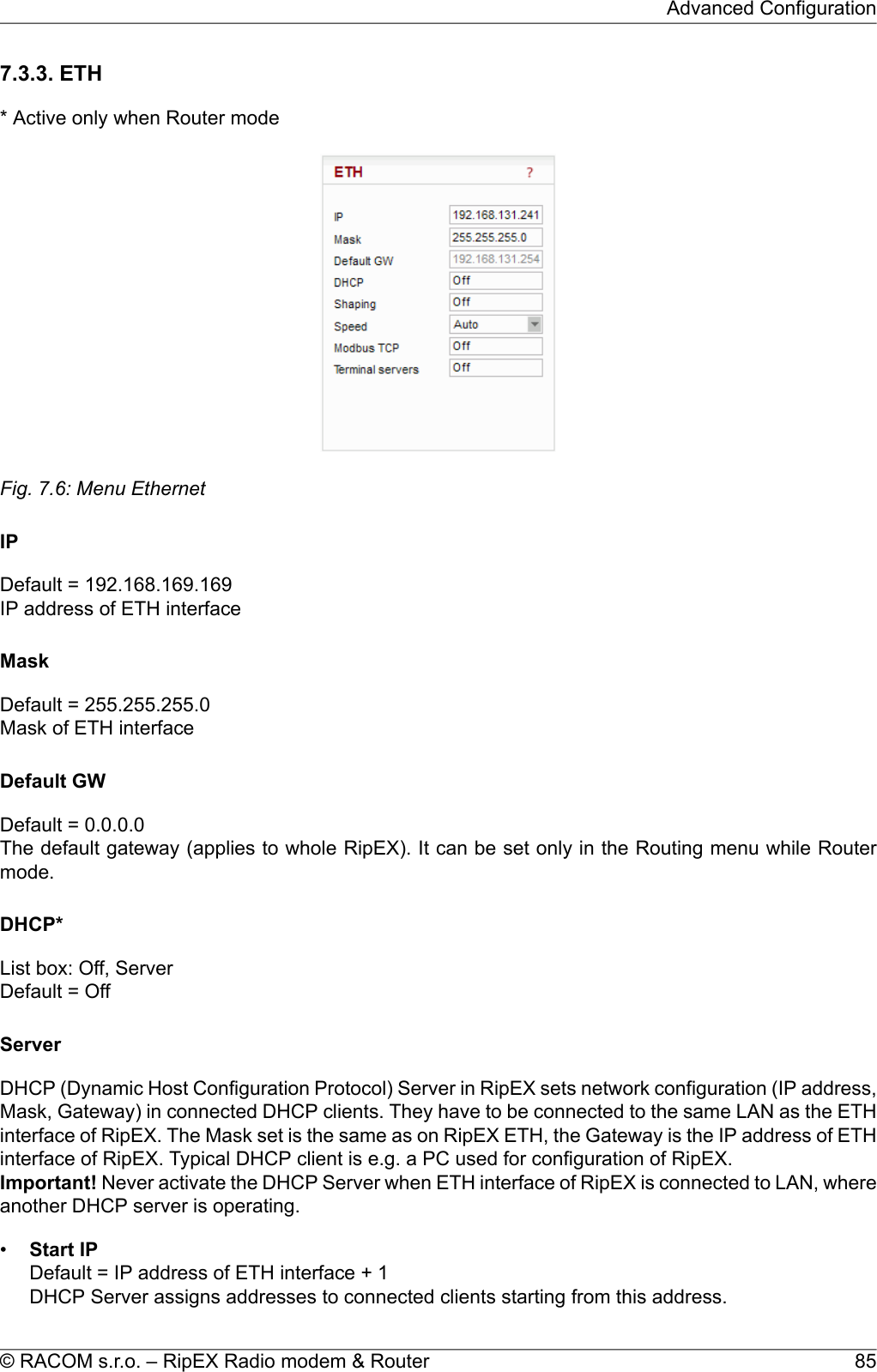
![•End IPDHCP server assigns IP addresses to clients from the range defined by Start IP and End IP (inclus-ive).•No of leasesDefault = 5 [1 - 255]Maximum number of DHCP client(s) which can RipEX simultaneously serve. It can not be morethan the number of addresses available in the Start IP - End IP range.•Lease timeout [DD:HH:MM:SS]Default = 1 day (max. 10 days)A DHCP Client has to ask DHCP Server for refresh of the received configuration within this timeout,otherwise the Lease expires and the same settings can be assigned to another device (MAC).•Assigned IP'sTable shows MAC addresses of Clients and IP addresses assigned to them by the Server. Expirationis the remaining time till the respective Lease expires. If the assigned IP addresses are required tobe deleted, set DHCP Server to Off, then action Apply and set DHCP server to On (+Apply) again.•Preferred IP'sIt is possible to define which IP should be assigned by the Server to a specific MAC. The requestedIP has to be within the Start IP – End IP range.Shaping*List box: On, OffDefault = OffEthernet interface could easily overload the Radio channel. Because of that, it is possible to shapetraffic received from the ETH interface.If On, specified volume of Data [Bytes] in specified Period [sec] is allowed to enter the RipEX from ETHinterface. The first packet which exceeds the limit is stored in the buffer and transmitted when newPeriod starts. Further over-limit packets are discarded.SpeedList box: Auto, 100baseTX/Full, 100baseTX/Half, 10baseT/Full, 10baseT/HalfDefault = AutoCommunication speed on the Ethernet interface.Modbus TCP*Use this setttings only for Modbus TCP Master when it communicates with both types of Modbusslaves using either Modbus RTU or Modbus TCP protocols. Or when TCP/IP communication shouldrun locally between Modbus Master and RipEX in Modbus TCP network. Read Help and Applicationnote Modbus in RipEX.For more information refer to the manual Application note / Modbus TCP1.** - denotes items to be used only when either all or some RTUs (Remote Telemetry Unit) on remotesites are connected via RS232 or RS485 interface to RipEX, using the Modus RTU protocol. Thenautomatic conversion between Modbus TCP and Modbus RTU protocols takes place for such units.List box: On, OffDefault = Off1http://www.racom.eu/eng/products/m/ripex/app/modbus.htmlRipEX Radio modem & Router – © RACOM s.r.o.86Advanced Configuration](https://usermanual.wiki/Racom/RIPEX-154/User-Guide-1865807-Page-86.png)
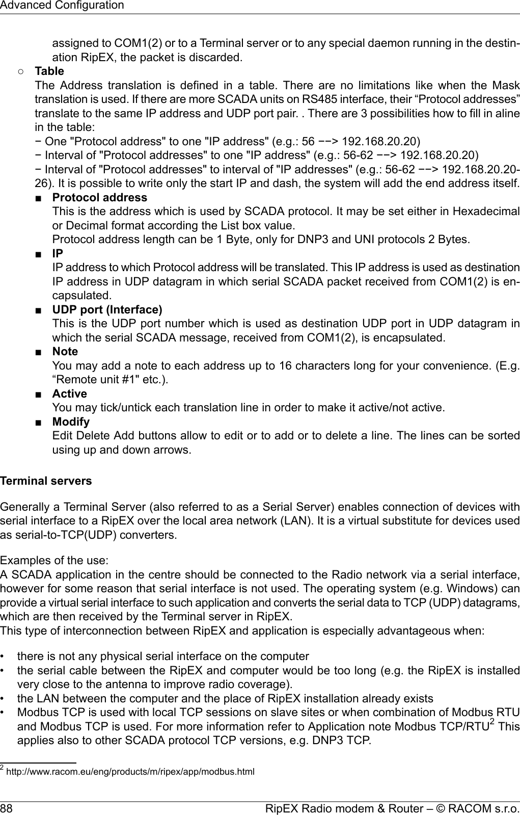
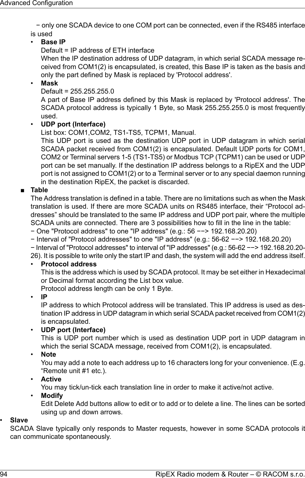
![•My TCP portDefault = 502 [1 - 65 535]TCP port used for Modbus TCP in RipEX.•TCP Keepalive [sec.]Default = 120 [0 - 16 380]TCP socket in RipEX is kept active after the receipt of data for the set number of seconds.•Broadcast**List box: On, OffDefault = OffSome Master SCADA units send broadcast messages to all Slave units. SCADA application typicallyuses a specific address for such messages. RipEX (Protocol utility) converts such message to anIP broadcast and broadcasts it to all RipEX units resp. to all SCADA units within the network.If On, the address for broadcast packets in SCADA protocol has to be defined:•Broadcast address format - List box Hex, Dec - format in which broadcast address is defined.•Broadcast address - address in the defined format (Hex, Dec)•Address translationList box: Table, MaskDefault = MaskIn a SCADA protocol, each SCADA unit has a unique address, a "Protocol address". In RipEX Radionetwork, each SCADA unit is represented by an IP address (typically that of ETH interface) and aUDP port (that of the protocol daemon or the COM port server to which the SCADA device is con-nected via serial interface).A translation between "Protocol address" and the IP address & UDP port pair has to be done. Itcan be done either via Table or via Mask.Each SCADA message received from serial interface is encapsulated into a UDP/IP datagram,where destination IP address and destination UDP port are defined according the settings of Addresstranslation.○MaskTranslation using Mask is simpler to set, however it has some limitations:− all IP addresses used have to be within the same network, which is defined by this Mask− the same UDP port is used for all the SCADA units, which results in the following limitations:− SCADA devices on all sites have to be connected to the same interface (COM1 or COM2)− only one SCADA device to one COM port can be connected, even if the RS485 interface isused■Base IPDefault = IP address of ETH interfaceWhen the IP destination address of the UDP datagram, in which serial SCADA messagereceived from COM1(2) is encapsulated, is created, this Base IP is taken as the basis andonly the part defined by Mask is replaced by 'Protocol address'.■MaskDefault = 255.255.255.0A part of Base IP address defined by this Mask is replaced by 'Protocol address'. The SCADAprotocol address is typically 1 Byte, so Mask 255.255.255.0 is most frequently used.■UDP port (Interface)List box: COM1, COM2, TS1-TS5, TCPM1, Manual.Default = COM1This UDP port is used as the destination UDP port in the UDP datagram in which serialSCADA packet received from COM1(2) is encapsulated. Default UDP ports for COM1, COM2or Terminal servers 1-5 (TS1-TS5) or Modbus TCP (TCPM1) can be used or UDP port canbe set manually. If the destination IP address belongs to a RipEX and the UDP port is not87© RACOM s.r.o. – RipEX Radio modem & RouterAdvanced Configuration](https://usermanual.wiki/Racom/RIPEX-154/User-Guide-1865807-Page-87.png)
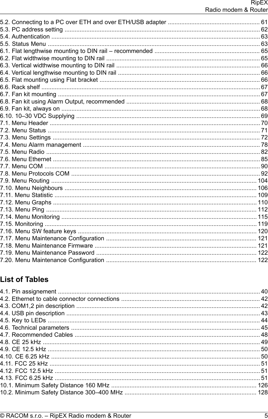
![Fig. 7.7: Menu COMTypeList box: possible valuesDefault = RS232COM1 is always RS232, COM2 can be configured to either RS232 or RS485.Note: The settings of Data rate, Data bits, Parity and Stop bits of COM port and connected device mustmatch.Baud rate [bps]List box: standard series of rates from 300 to 115200 bpsDefault = 19200Select Baud rate from the list box: 300 to 115200 bps rates are available.Serial ports use two-level (binary) signaling, so the data rate in bits per second is equal to the symbolrate in baudsData bitsList box: 8, 7Default = 8The number of data bits in each character.ParityList box: None, Odd, EvenDefault = NoneWikipedia: Parity is a method of detecting errors in transmission. When parity is used with a serialport, an extra data bit is sent with each data character, arranged so that the number of 1-bits in eachcharacter, including the parity bit, is always odd or always even. If a byte is received with the wrongnumber of 1s, then it must have been corrupted. However, an even number of errors can pass theparity check.Stop bitsList box: possible valuesDefault = 1RipEX Radio modem & Router – © RACOM s.r.o.90Advanced Configuration](https://usermanual.wiki/Racom/RIPEX-154/User-Guide-1865807-Page-90.png)
![Wikipedia: Stop bits sent at the end of every character allow the receiving signal hardware to detectthe end of a character and to resynchronise with the character stream.Idle [bytes]Default = 5 [0 - 2000]This parameter defines the maximum gap (in bytes) in the received data stream. If the gap exceedsthe value set, the link is considered idle, the received frame is closed and forwarded to the network.MRU [bytes]Default = 1600 [1 - 1600]MRU (Maximum Reception Unit) — an incoming frame is closed at this size even if the stream of bytescontinues. Consequently, a permanent data stream coming to a COM results in a sequence of MRU-sized frames sent over the network.Note 1: very long frames (>800 bytes) require good signal conditions on the Radio channel and theprobability of a collision increases rapidly with the length of the frames. Hence if your application canwork with smaller MTU, it is recommended to use values in 200 – 400 bytes range.Note 2: this MRU and the MTU in Radio settings are independent. However MTU should be greateror equal to MRU.Flow controlList box: None, RTS/CTSDefault = NoneRTS/CTS (Request To Send / Clear To Send) hardware flow control (handshake) between the DTE(Data Terminal Equipment) and RipEX (DCE - Data Communications Equipment) can be enabled inorder to pause and resume the transmission of data. If RX buffer of RipEX is full, the CTS goes down.Note: RTS/CTS Flow control requires a 5-wire connection to the COM port.Protocol*List box: possible valuesDefault = NoneEach SCADA protocol used on serial interface is more or less unique. The COM port daemon performsconversion to standard UDP datagrams used in RipEX Radio network. Each protocol has its individualconfiguration parameters, which are described in separate Help page (accessible from configurationlight box Protocol - click on Protocol, then on Help). Protocol “None” simply discards any data receivedby the COM port or from the network, which means that the respective COM port is virtually disconnectedfrom the RipEX.91© RACOM s.r.o. – RipEX Radio modem & RouterAdvanced Configuration](https://usermanual.wiki/Racom/RIPEX-154/User-Guide-1865807-Page-91.png)
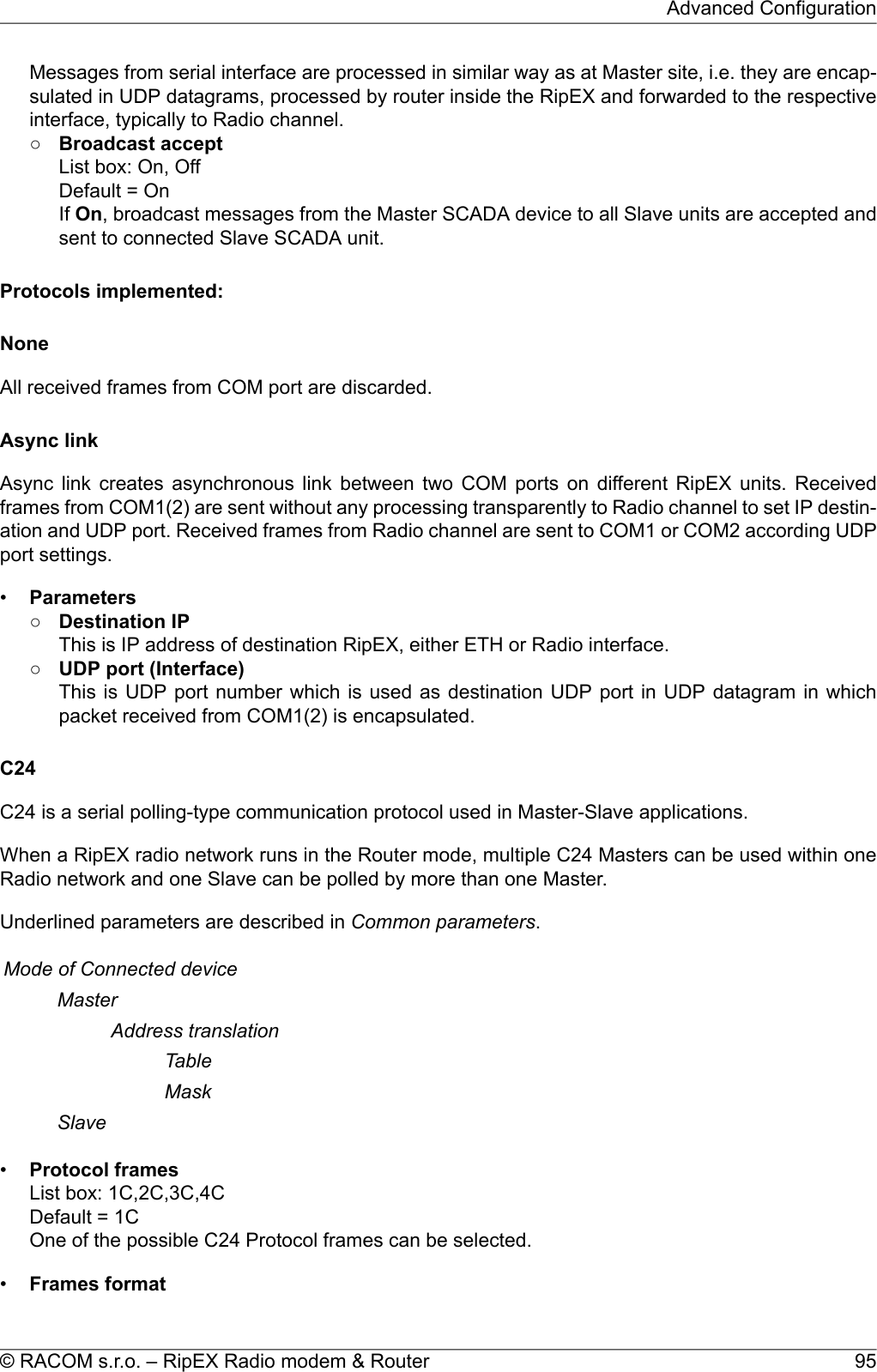
![List box: Format1,Format2,Format3,Format4,Format5Default = Format1One of the possible C24 Frames formats can be selected. According to the C24 protocol specification,it is possible to set Frames formats 1-4 for Protocol frames 1C-3C and formats 1-5 for 4C.Note: The RipEX accepts only the set Protocol frames and Frames format combination. All othercombinations frames are discarded by the RipEX and not passed to the application.•Local ACKList box: Off, OnDefault = OffAvailable for Protocol frame 1C only. When On, ACK on COM1(2) is send locally from this unit, notover the Radio channel.CactusCactus is a serial polling-type communication protocol used in Master-Slave applications.When a RipEX radio network runs in the Router mode, multiple Cactus Masters can be used withinone Radio network and one Slave can be polled by more than one Master.Underlined parameters are described in Common parameters.Mode of Connected deviceMasterBroadcastNote: There is not the possibility to set Broadcast address, sinceCactus broadcast messages always have the address 0x00. Hencewhen the Broadcast is On, packets with this destination are handledas broadcasts.Address translationTableMaskSlaveBroadcast accept•Max gap timeout [ms]Default = 30The longest time gap for which a frame can be interrupted and still received successfully as oneframe. It should not be set below 10ms, while 15–40 ms should be OK for a typical Cactus protocoldevice.ComliComli is a serial polling-type communication protocol used by Master-Slave application.When RipEX radio network run in Router mode, more Comli Masters can be used within one Radionetwork and one Slave can be polled by more Masters.Broadcasts packets are not used, so the configuration is using only some parameters describedCommon parameters.Mode of Connected deviceRipEX Radio modem & Router – © RACOM s.r.o.96Advanced Configuration](https://usermanual.wiki/Racom/RIPEX-154/User-Guide-1865807-Page-96.png)
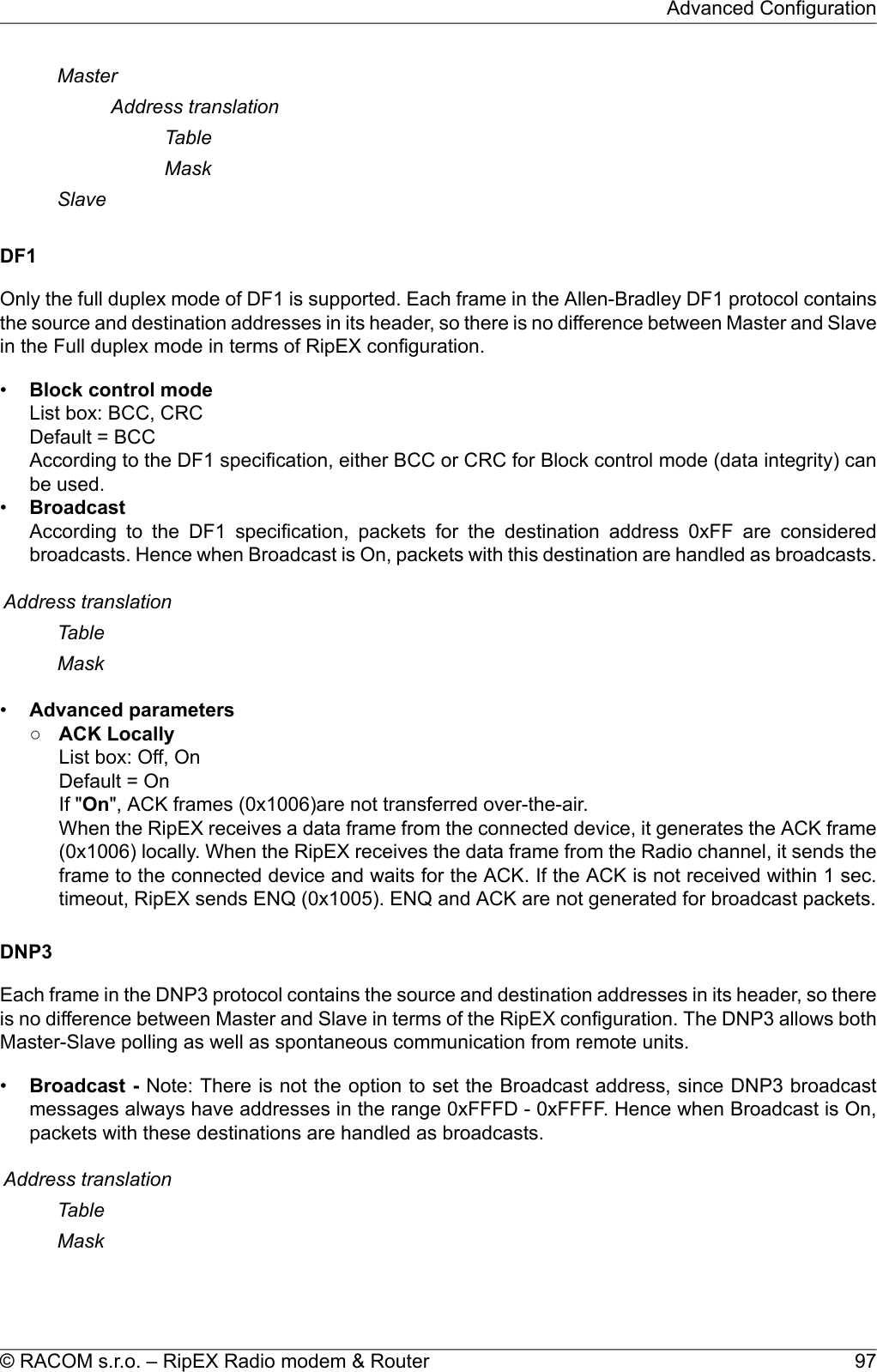
![Note: There is not a possibility to set the Broadcast address, since ITTFlygt broadcast messages always have the address 0xFFFF. Hence whenthe Broadcast is On, packets with this destination are handled as broad-casts.•First Slave AddressDefault = 1Slave addresses are not defined in the ITT Flygt protocol. HoweverSlave addresses have to be defined in the RipEX network. This is theFirst Slave address in decimal format.•Number of SlavesDefault = 1Since the ITT Flygt protocol Master (centre) polls the Slaves (remotes)one by one without any addressing, number of slaves has to be defined.Address translationTableMaskSlaveBroadcast accept•Wait timeout [ms]Default = 5000An ITT Flygt Slave sometimes sends the WAIT COMMAND (0x13) to its Master. The RipEX doesnot accept the next WAIT COMMAND (discards it), till the Wait timeout does not expire. The Re-commended value is in the 1-10 seconds range.ModbusModbus RTU is a serial polling-type communication protocol used by Master-Slave application.When RipEX radio network run in Router mode, more Modbus Masters can be used within one Radionetwork and one Slave can be polled by more Masters.Modbus protocol configuration uses all parameters described in Common parameters.Mode of Connected deviceMasterBroadcastAddress translationTableMaskSlaveBroadcast acceptProfibusRipEX supports Profibus DP (Process Field Bus, Decentralized Periphery) the widest-spread versionof Profibus. The Profibus protocol configuration uses all parameters described inCommon parameters.99© RACOM s.r.o. – RipEX Radio modem & RouterAdvanced Configuration](https://usermanual.wiki/Racom/RIPEX-154/User-Guide-1865807-Page-99.png)
![Mode of Connected deviceMasterBroadcastAddress translationTableMaskSlaveBroadcast acceptRP570RP570 is a serial polling-type communication protocol used in Master-Slave applications.When a RipEX radio network runs in the Router mode, multiple RP570 Masters can be used withinone Radio network and one Slave can be polled by more than one Master.Underlined parameters are described in Common parameters.Mode of ConnecteddeviceMaster•Local simulation RBList box: Off, OnDefault = OffThe RP570 protocol Master very often transmits the RB packets (hold packets) solely to checkwhether slaves are connected. In order to minimize the Radio channel load, the RipEX can beconfigured to respond to these packets locally and not to transmit them to the slaves over the Radiochannel.If On, the RipEX responds to RB packets received from the RP 570 master locally over the COMinterface. However from time to time (RB period) the RB packets are transferred over the networkin order to check whether the respective slave is still on. When the RB response from the slave tothis RB packet is not received over the Radio channel within the set RB timeout, i.e. the respectiveslave is out of order, the central RipEX stops local answering to RB packets from the master for therespective slave.•RB Net period [s]Default = 10The RipEX responds to the RB packets locally and in the set RB period the RB packets are trans-ferred over the network.•RB Net timeout [s]Default = 10 (maximum=8190)Whenever an RB packet is sent over the network, the set RB Net timeout starts. When the RB re-sponse from the remote unit (slave) is not received within the timeout, i.e. the respective slave isout of order, the central RipEX stops the local answering to RB packets from the master for the re-spective slave.Address translationRipEX Radio modem & Router – © RACOM s.r.o.100Advanced Configuration](https://usermanual.wiki/Racom/RIPEX-154/User-Guide-1865807-Page-100.png)
![TableMaskSlaveSlave•Local simulation RBList box: Off, OnDefault = OffThe RP570 Slave expects to receive RB packets from the Master. When the Local simulation RBon the Master is On, the RB packets are transferred over the Radio channel only in the RB Netperiod (see Master settings). The Local simulation RB has to be set the same (On or Off) on allsites in the network, i.e. on the master as well as all slaves.If On, the RipEX generates RB packets locally and transmits them over the COM interface in theRB Request period and expects the RB response for each RB packet from the RP570 Slave withinthe RB Response timeout. When the RipEX does not receive the response(s) from the RP570 slave,the RipEX does not respond to the RB packet from the Master which it receives over the Radiochannel.•RB Request period [ms]Default = 200 (maximum=8190)RipEX sends locally RB packets to the connected RTU in the set period.•RB Response timeout [ms]Default = 500 (maximum=8190)The RipEX expects a response to the RB packet within the set timeout. If it is not received, theRipEX does not respond to RB packets from the Master received over the Radio channel.•RTU address (Hex)Default = 01Active only when the Local simulation RB is On. The connected RTU’s address is supposed to befilled in. This address (0x00-0xFF) is used in the RB packets generated locally in the RipEX andtransmitted over the COM.UNIUNI is the "Universal" protocol utility designed by RACOM. It is supposed to be used when the applic-ation protocol is not in the RipEX list and the addressed mode of communication is preferable in thenetwork (which is a typical scenario). The key condition is that messages generated by the Masterapplication device always contain the respective Slave address and that address (or its relevant part)position, relative to the beginning of the message (packet, frame), is always the same (Address position).Generally two communication modes are typical for UNI protocol: In the first one, communication hasto be always initiated by the Master and only one response to a request is supported; in the secondmode, Master-Master communication or combination of UNI protocol with ASYNC LINK protocol andspontaneous packets generation on remote sites are possible.The UNI protocol is fully transparent, i.e. all messages are transported and delivered in full, withoutany modifications.Underlined parameters are described in Common parameters.101© RACOM s.r.o. – RipEX Radio modem & RouterAdvanced Configuration](https://usermanual.wiki/Racom/RIPEX-154/User-Guide-1865807-Page-101.png)
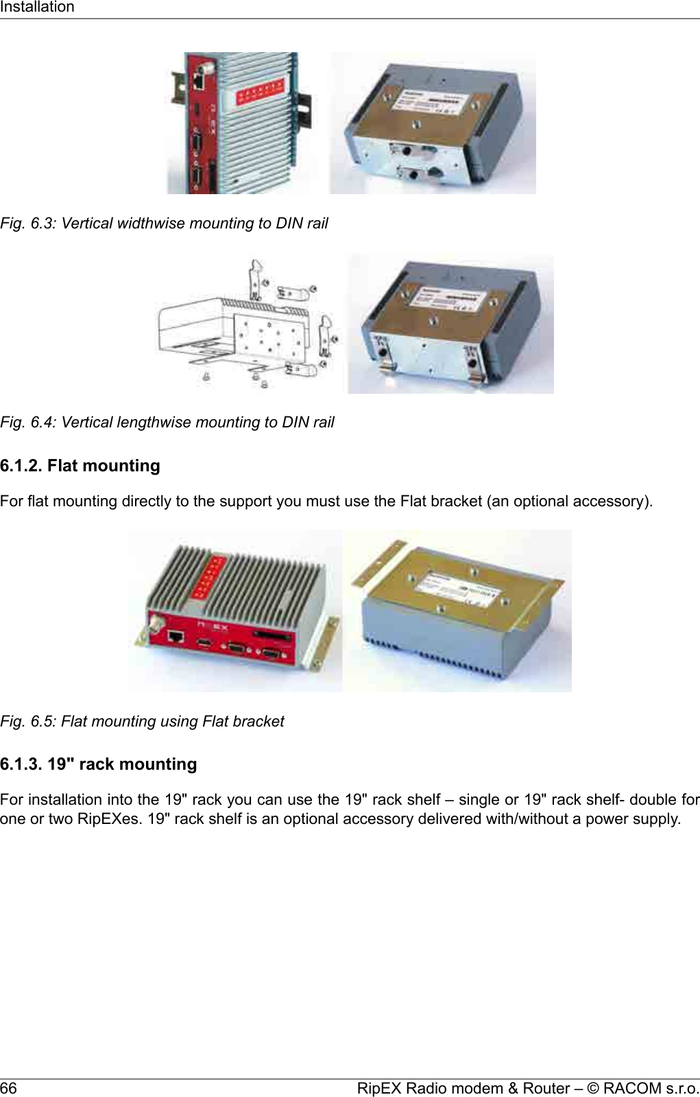
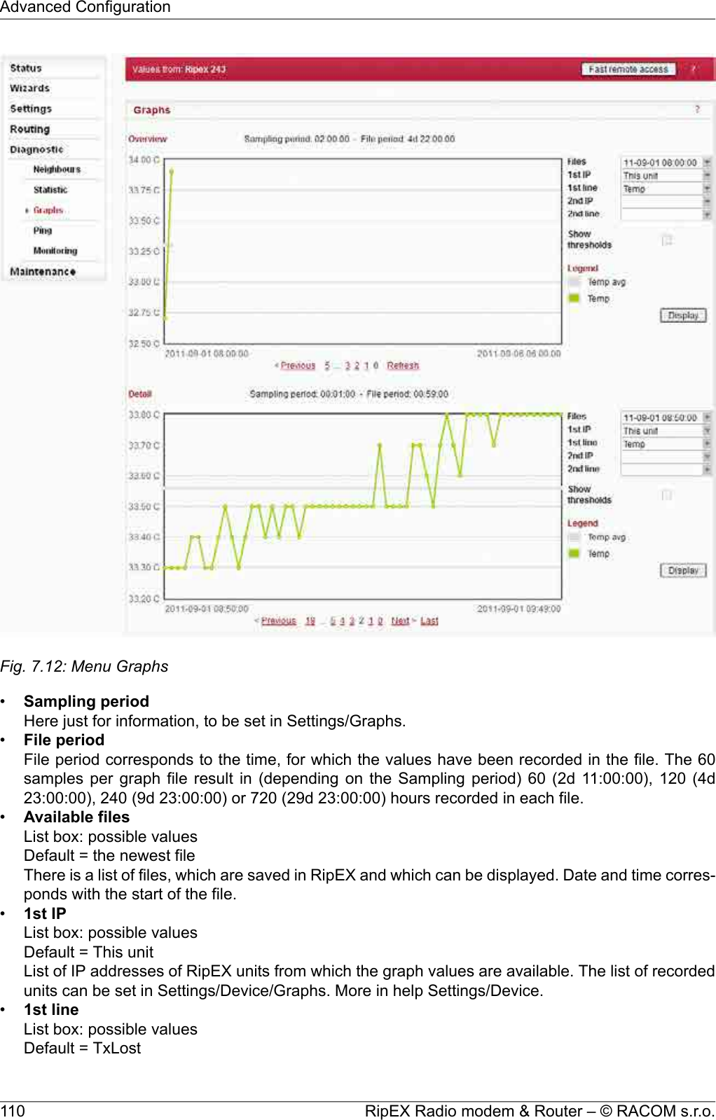
![• red background indicates, that the item is monitored for alarm and its average value is in the alarmrange (Settings/Device/Alarm management)• when the value of RSS, DQ, Ucc, Temp, PWR, VSWR is not known, N/A is displayed. These N/Avalues are not displayed in Graphs•Ucc, Temp, PWR, VSWR are refreshed every 1s. The other values in both, Neighbours and Statisticstables are refreshed every 20s• IP addresses:○Bridge modeDue to broadcast pattern of traffic in Radio channel, all frames generated by user application(s)cumulate in one line in the Neighbour table. When diagnostic or service frames (e.g. Watchedvalues) are transmitted in the network, they are listed in separate lines, distinguished by IP ad-dress of their respective Ethernet interfaces.○Router modeMAC addresses of Radio interface are used for link layer communication on Radio channel.When RipEX knows the IP address corresponding with the MAC address (the IP has been thedestination IP of a packet transferred), IP address is displayed. If the IP address is not known,the MAC address is displayed.The first three columns are logged by the receiving RipEX itself.○Received headers [Count]Total number of frame headers received from the respective RipEX.○RSS [dBm]Received Signal Strength.○DQData Quality of received frames. The DQ value is about proportional to BER (bit error ratio) andabout independent of the data rate and modulation used. Consequently when data rate is lowered,the DQ value increases and the other way round. Judging the DQ values requires experience,rule-of-thumb figures are as followsvalues: DQ below 100 means the link is unusable, aroundt125 short packets starthould getting through, about 160 and above can be considered “good”values.The remaining columns contain values broadcasted by neighbouring units in their Watched valuesbroadcasting periods(Settings/Device/Neighbours&Statistics).○TxLost [%]The probability of a transmitted frame being lost (100 * Lost frames / All transmitted frames).This value is broadcasted only when Router mode is used and ACK is On.○Ucc [V]Power voltage measured on power input.○Temp [°C]Temperature inside of the RipEX.○PWR [W]The actual value of Radio output power measured by RipEX itself.○VSWRVoltage Standing Wave Ratio (1.0=best, 1.0–1.8=acceptable, >2.5=indicates a serious problemin antenna or feeder)○Packets [Rx/Tx]The total number of packets received from / transmitted to ETH, COM1, COM2 interfaces.Can be used for interface activity diagnostic.RipEX Radio modem & Router – © RACOM s.r.o.108Advanced Configuration](https://usermanual.wiki/Racom/RIPEX-154/User-Guide-1865807-Page-108.png)
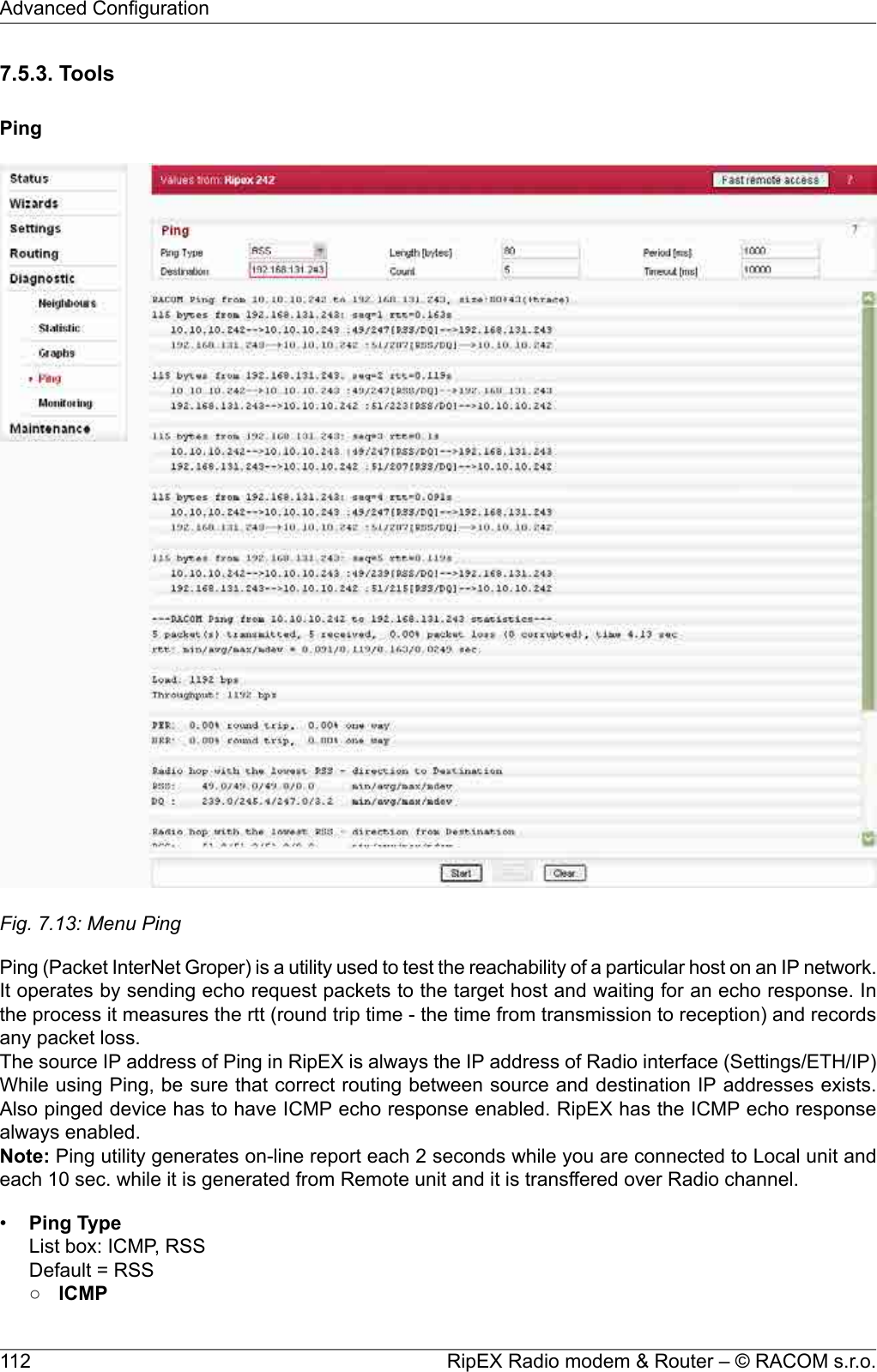
![This is a standard ICMP (Internet Control Message Protocol) ping. It can be used against eitherRipEX or any device connected to RipEX Radio network.○RSSRSS Ping Type uses a special UDP packets and provides extension report which includes:■ RSS and DQ information for each radio hop for each individual ping■RSS and DQ statistic (average, min., max.) for radio hop with the lowest RSS in both directions■ Histogram of rtt of pings divided to 5 intervals■ Load and Throughput■ PER (Packet Error Rate)■ BER (Bit Error Rate)•DestinationDefault = 127.0.0.1Destination IP address•Length [bytes]Default = 80The length of user data, the range from 8 to 4096 Byte. Some overhead to this Length is alwaysadded like these:ICMP - 28 bytesRSS - 43 bytes for IP+UDP+RACOM header + 8 bytes (Trace-RSS and DQ) per each radio hop +4 bytes (marking in server)RSS ping can not be longer than 3/4 MTU.•CountDefault = 5Number of pings to be transmitted. The allowed range is from 1 to 1024.•Period [ms]Default = 1000When this Period expires, the next Ping is transmitted. The range is from 1000 (1 sec.) to 3600000(1 hour).•Timeout [ms]Default = 10000Timeout from 1000 (1 sec.) to 3600000 (1 hour).When ping (the response) is not received within this timeout, it is counted as lost.•ReportA short report is generated in run-time for each individual ping packet. When the Ping utility isstopped, an overall statistic report is displayed.○ICMPStandard Linux ping reports are provided:■Run-time report:"88 bytes from 192.168.131.243: icmp_req=1 ttl=63 time=360 ms"88 bytes = total packet lenght192.168.131.243 = destination IPicmp_req = ping sequence numberttl = time to live, max. number of hops (passing through router) of the packet in the networktime = rtt (round trip time), the time from transmission of ICMP echo request to reception ofICMP echo response■Statistic report:"5 packets transmitted, 5 received, 0% packet loss, time 4002ms""rtt min/avg/max/mdev = 327.229/377.519/462.590/45.516 ms"time = total time of ping utility (From Start to Stop buttons)rtt min/avg/max/mdev = round trip time, minimal/average/maximal/standard deviation○RSS■Run-time report:113© RACOM s.r.o. – RipEX Radio modem & RouterAdvanced Configuration](https://usermanual.wiki/Racom/RIPEX-154/User-Guide-1865807-Page-113.png)
!["131 bytes from 192.168.131.243: seq=1 rtt=0.805s""10.10.10.241-->10.10.10.242 :56/209[RSS/DQ]-->10.10.10.243:51/225[RSS/DQ]-->192.168.131.243""192.168.131.243-->10.10.10.242 :46/214[RSS/DQ]-->10.10.10.241 :57/213[RSS/DQ]-->10.10.10.241"131 bytes = RSS packet size (RACOM header + data + trace)10.10.10.242 = repeater IP192.168.131.243 = destination IPseq = ping sequence numberrtt = round trip time, the time from transmission to reception■Statistic report:"5 packet(s) transmitted, 5 received, 0.00% packet loss (0 corrupted), time 4.48 sec""rtt: min/avg/max/mdev = 0.371/0.483/0.805/0.166 sec."corrupted = number of packets which have been received (UDP header is OK) neverthelesstheir data have been corrupted (CRC over data is not OK)time = the total time of ping utility (From Start to Stop buttons)rtt min/avg/max/mdev = round trip time, minimal/average/maximal/standard deviation"Load: 1098 bps""Throughput: 1098 bps"Load = the load generated by Ping utilityThroughput = the througput provided by Radio network"PER: 0.00% round trip, 0.00% one-way""BER: 0.00% round trip, 0.00% one-way"PER - Packet Error Rate, i.e. the probability of a packet being lost. It is calculated for boththe whole round trip and a one-way trip.BER - Bit Error Rate, the probability of one bit received with incorrect value. Only packets,no bits can be lost in packet radio network. When a single bit is received wrong, the wholepacket is lost. The BER is calculated from the PER based on this assumption."Radio hop with lowest RSS – direction to Destination""RSS: 56.0/56.8/58.0/0.7 min/avg/max/mdev""DQ : 208.0/219.0/232.0/9.4 min/avg/max/mdev""Radio hop with lowest RSS – direction from Destination""RSS: 56.0/56.4/57.0/0.5 min/avg/max/mdev""DQ : 208.0/216.2/223.0/5.3 min/avg/max/mdev"There is RSS (Received Signal Strenght) and DQ (Data Quality) information from the radiohop with lowest RSS, separately for both directions (To and From the destination RipEX).The mdev values for both the RSS and DQ are provided, giving idea on signal homogeneity.The lower values are recorded, the more reliable the link should be. The “Homogenity” showsthe jitter of RSS values from individual pings."rtt histogram (time interval in sec.: %, count)"" 0.000 - 2.500: 100.00% 5" XXXXXXXXXX" 2.500 - 5.000: 0.00% 0"" 5.000 - 7.500: 0.00% 0"" 7.500 - 10.000: 0.00% 0""10.000 - inf: 0.00% 0"RipEX Radio modem & Router – © RACOM s.r.o.114Advanced Configuration](https://usermanual.wiki/Racom/RIPEX-154/User-Guide-1865807-Page-114.png)
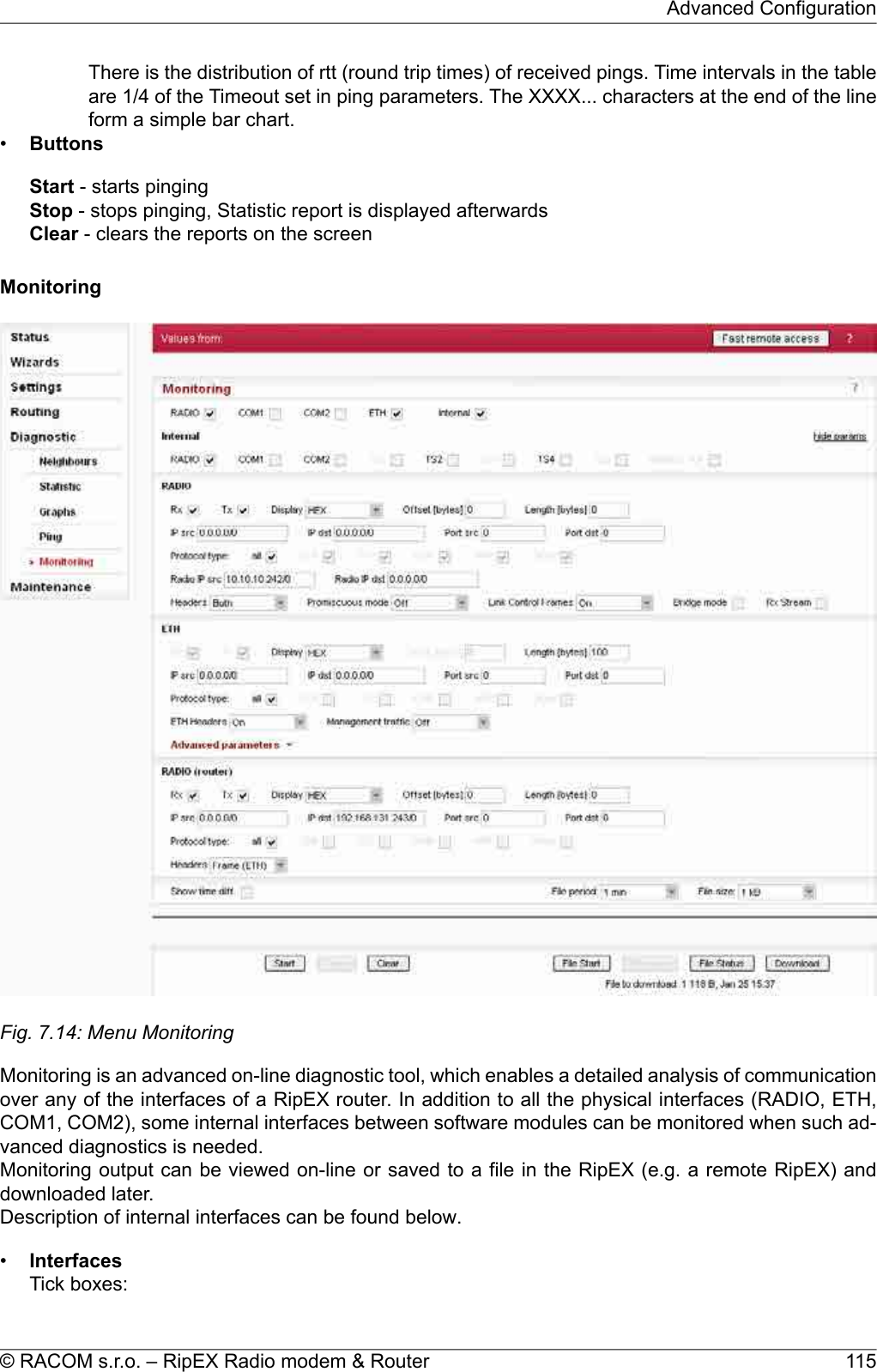
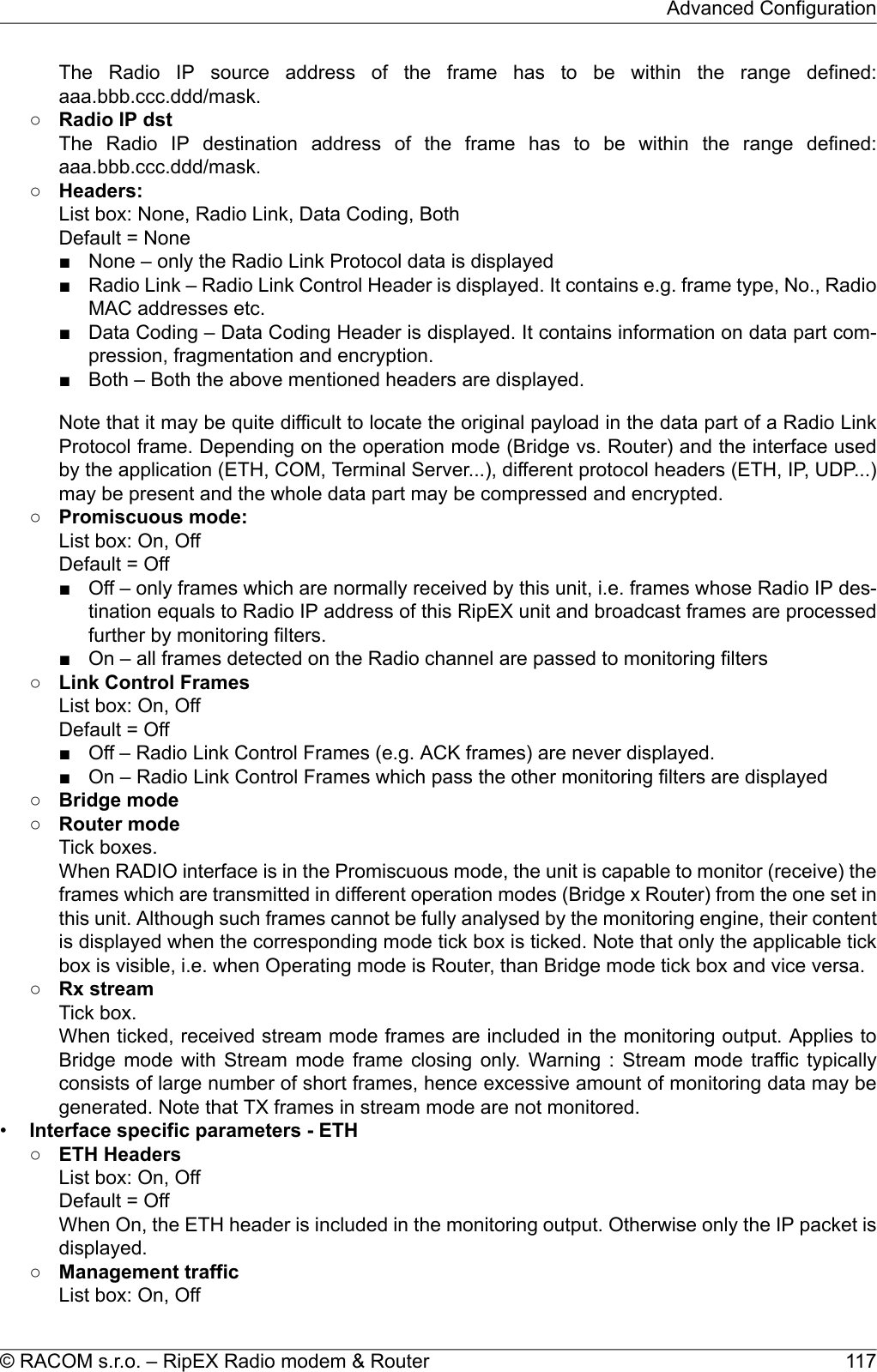
![RADIO, COM1, COM2, ETH, InternalWhen ticked, the setting for the respective interface(s) is enabled. When the "Internal" interface isticked, another set of interface tick-boxes appears as follows:Internal:RADIO, COM1, COM2, TS1, TS2, TS3, TS4, TS5, Modbus TCPWhen ticked, the setting for the respective internal interface(s) is enabled (see the description below).•Common parameters for all interfaces: Destination IP address○Rx○TxTick boxes.When ticked, packets (frames, messages) coming in the respective direction are monitored. Apacket is considered a Tx one when it comes out from the respective software module (e.g.RADIO or Terminal Server) and vice versa. When an external interface (e.g. COM(phy)) ismonitored, the Tx also means packets being transmitted from the RipEX over the respectiveinterface (Rx means "received"}. Understanding the directions over the internal interfaces maynot be that straightforward, please consult the diagram below for clarification.Please note the separate monitoring of Rx or Tx frames is not possible at the ETH interface.○DisplayList box: HEX, HEX+ASCII, ASCIIDefault = HEXThe format of monitoring output.○Offset [bytes]Default = 0Number of bytes from the beginning of packet/frame, which will not be displayed. The Lengthof bytes will be displayed starting from the immediately next byte.This feature is not available at the ETH interface.○Length [bytes]Default = 100Number of bytes, which will be displayed from each packet/frame.Example: Offset=2, Length=4 means, that bytes from the 3rd byte to the 6th (inclusive) will bedisplayed:Data (HEX): 01AB3798A28593CD6B96Monitoring output: 3798A285•Filter parameters for IP/ARP packets(available for RADIO, ETH and Internal RADIO (router), COMn(router), TSn(router), ModbusTCP(router)):○IP srcIP source address range in the following format: aaa.bbb.ccc.ddd/mask○IP dstIP destination address range in the following format: aaa.bbb.ccc.ddd/mask○Port srcTCP/UDP source port (range) in the following format: aaaa(-bbbb)○Port dstTCP/UDP destination port (range) in the following format: aaaa(-bbbb)○Protocol type(available for RADIO, ETH and Internal RADIO (router))Tick boxes for displaying specific protocols only. "Other" means displaying everything exceptthe four listed protocols (even non-IP frames in case of the RADIO interface).•Interface specific parameters - RADIO○Radio IP srcRipEX Radio modem & Router – © RACOM s.r.o.116Advanced Configuration](https://usermanual.wiki/Racom/RIPEX-154/User-Guide-1865807-Page-116.png)
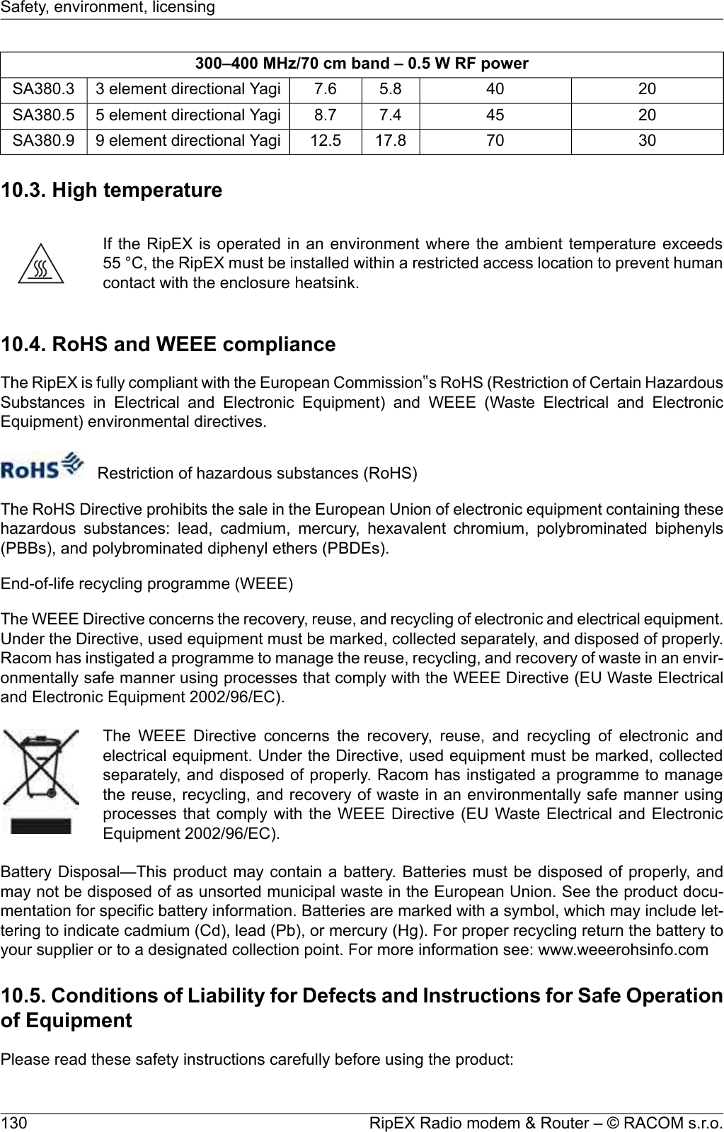
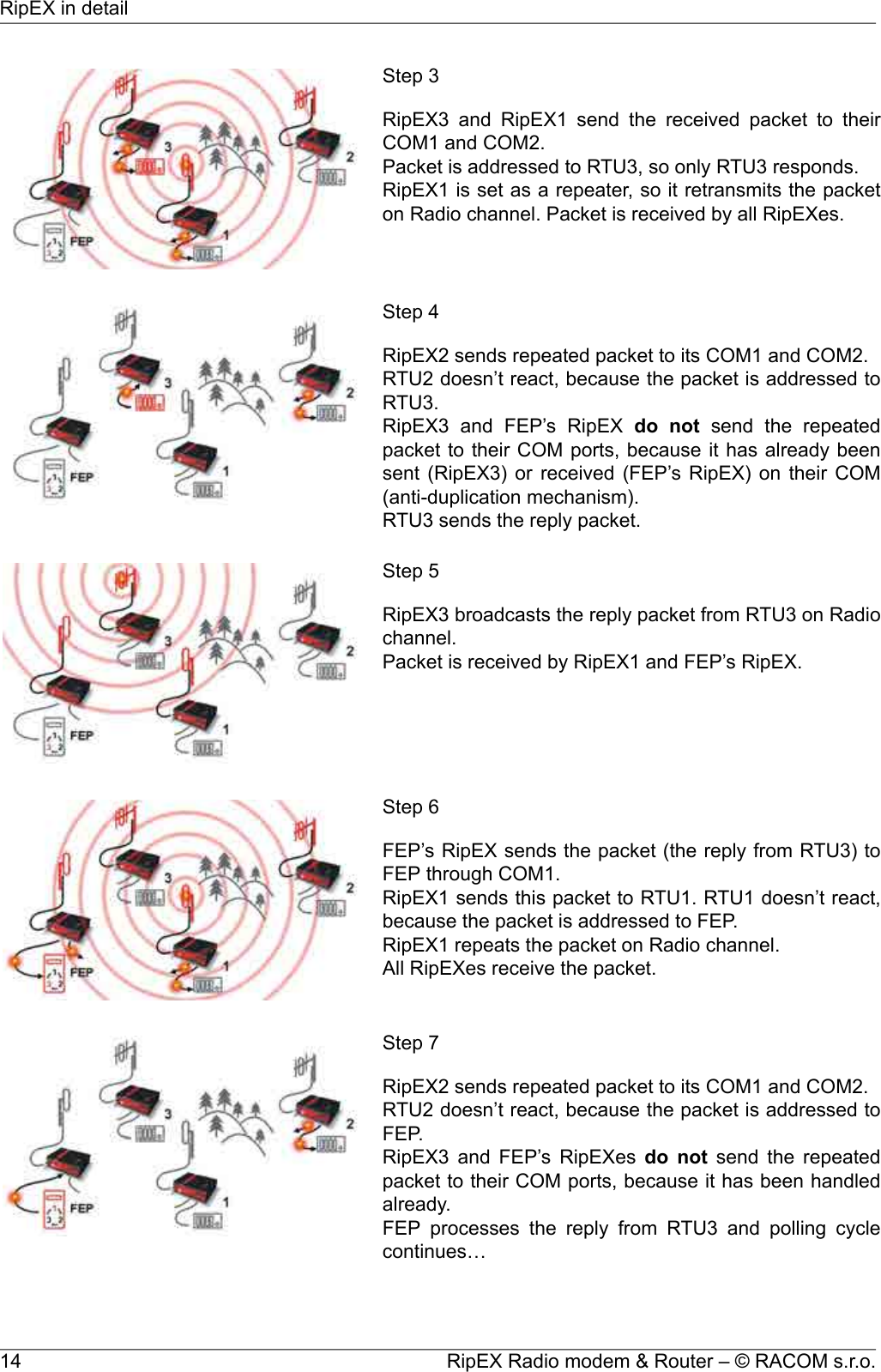
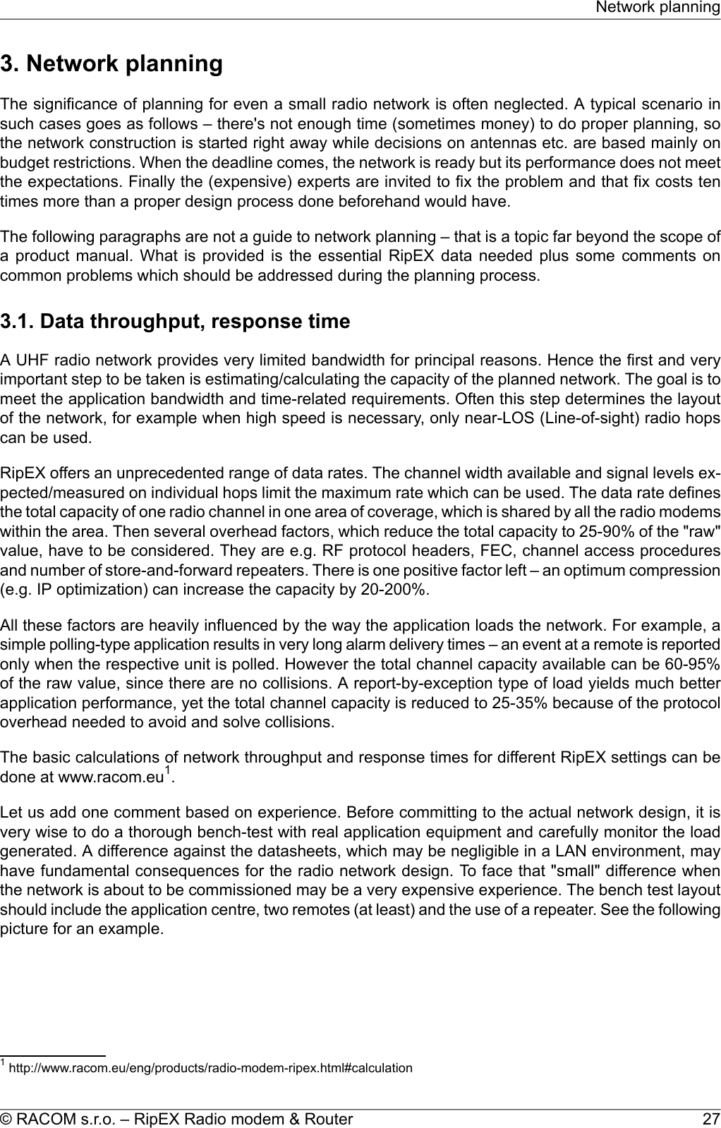
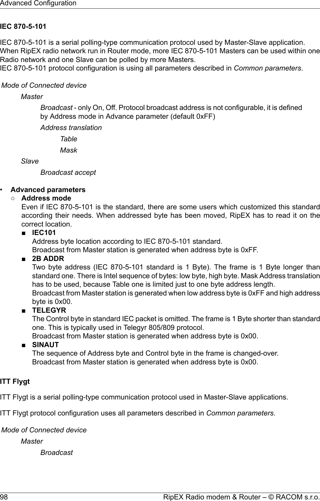
![10. Safety, environment, licensing10.1. FrequencyThe radio modem must be operated only in accordance with the valid frequency license issued by na-tional frequency authority and all radio parametres have to be set exactly as listed.ImportantUse of frequencies between 406.0 and 406.1 MHz is worldwide-allocated only for Interna-tional Satellite Search and Rescue System. These frequencies are used for distress beaconsand are incessantly monitored by the ground and satellite Cospas-Sarsat system. Otheruse of these frequencies is forbidden.10.2. Safety distanceSafety distances with respect to the US health limits of the electromagnetic field intensityare in Minimum Safety Distance tables below, calculated for different antennas andRipEX power levels. The distances were calculated according to (doplnit normu) andapply to far-field region only. Whenever the result is comparable or smaller than the ac-tual size of the respective antenna, the field intensity is even smaller than the far-fieldbased calculation and the safety limit is never exceeded. For output power 0.2 W orlower the safety limit is not exceeded at any distance and any of the antennas.The minimal safe distance is typically ensured by the antenna position on a mast. When special install-ation is required, the conditions of the standard EN 50385: 2002 have to be met. The distance betweenthe persons and antenna shown in the table bellow comply with all applicable standards for humanexposure of general public to RF electromagnetic fields.Tab. 10.1: Minimum Safety Distance 160 MHz160 MHz/2 m band – 10 W RF powerDist. where the FCC limits are met forGain G[–]Gain G[dBi]Antenna descriptionAntennacodeGeneral Population/ Controlled Expos-ure [cm]General Population/ Uncontrolled Ex-posure [cm]901902.94.6single dipoleOV160.11202705.87.6stacked double dipoleOV160.21302806.38.05 element directional YagiSA160.321046017.812.59 element directional YagiSA160.5160 MHz/2 m band – 5 W RF powerDist. where the FCC limits are met forGain G[–]Gain G[dBi]Antenna descriptionAntennacodeGeneral Population/ Controlled Expos-ure [cm]General Population/ Uncontrolled Ex-posure [cm]601402.94.6single dipoleOV160.1901905.87.6stacked double dipoleOV160.2RipEX Radio modem & Router – © RACOM s.r.o.126Safety, environment, licensing](https://usermanual.wiki/Racom/RIPEX-154/User-Guide-1865807-Page-126.png)
![160 MHz/2 m band – 5 W RF power902006.38.05 element directional YagiSA160.315033017.812.59 element directional YagiSA160.5160 MHz/2 m band – 4 W RF powerDist. where the FCC limits are met forGain G[–]Gain G[dBi]Antenna descriptionAntennacodeGeneral Population/ Controlled Expos-ure [cm]General Population/ Uncontrolled Ex-posure [cm]601202.94.6single dipoleOV160.1801705.87.6stacked double dipoleOV160.2801806.38.05 element directional YagiSA160.313029017.812.59 element directional YagiSA160.5160 MHz/2 m band – 3 W RF powerDist. where the FCC limits are met forGain G[–]Gain G[dBi]Antenna descriptionAntennacodeGeneral Population/ Controlled Expos-ure [cm]General Population/ Uncontrolled Ex-posure [cm]451102.94.6single dipoleOV160.1701505.87.6stacked double dipoleOV160.2701506.38.05 element directional YagiSA160.312026017.812.59 element directional YagiSA160.5160 MHz/2 m band – 2 W RF powerDist. where the FCC limits are met forGain G[–]Gain G[dBi]Antenna descriptionAntennacodeGeneral Population/ Controlled Expos-ure [cm]General Population/ Uncontrolled Ex-posure [cm]40902.94.6single dipoleOV160.1601205.87.6stacked double dipoleOV160.2601306.38.05 element directional YagiSA160.310021017.812.59 element directional YagiSA160.5160 MHz/2 m band – 1 W RF powerDist. where the FCC limits are met forGain G[–]Gain G[dBi]Antenna descriptionAntennacodeGeneral Population/ Controlled Expos-ure [cm]General Population/ Uncontrolled Ex-posure [cm]30602.94.6single dipoleOV160.140905.87.6stacked double dipoleOV160.240906.38.05 element directional YagiSA160.37015017.812.59 element directional YagiSA160.5127© RACOM s.r.o. – RipEX Radio modem & RouterSafety, environment, licensing](https://usermanual.wiki/Racom/RIPEX-154/User-Guide-1865807-Page-127.png)
![160 MHz/2 m band – 0.5 W RF powerDist. where the FCC limits are met forGain G[–]Gain G[dBi]Antenna descriptionAntennacodeGeneral Population/ Controlled Expos-ure [cm]General Population/ Uncontrolled Ex-posure [cm]20452.94.6single dipoleOV160.130605.87.6stacked double dipoleOV160.230706.38.05 element directional YagiSA160.35011017.812.59 element directional YagiSA160.5Tab. 10.2: Minimum Safety Distance 300–400 MHz300–400 MHz/70 cm band – 10 W RF powerDist. where the FCC limits are met forGain G[–]Gain G[dBi]Antenna descriptionAntennacodeGeneral Population/ Controlled Expos-ure [cm]General Population/ Uncontrolled Ex-posure [cm]601302.94.6single dipoleOV380.1801805.87.6stacked double dipoleOV380.2801805.87.63 element directional YagiSA380.3902007.48.75 element directional YagiSA380.514031017.812.59 element directional YagiSA380.9300–400 MHz/70 cm band – 5 W RF powerDist. where the FCC limits are met forGain G[–]Gain G[dBi]Antenna descriptionAntennacodeGeneral Population/ Controlled Expos-ure [cm]General Population/ Uncontrolled Ex-posure [cm]40902.94.6single dipoleOV380.1601305.87.6stacked double dipoleOV380.2601305.87.63 element directional YagiSA380.3701407.48.75 element directional YagiSA380.510022017.812.59 element directional YagiSA380.9300–400 MHz/70 cm band – 4 W RF powerDist. where the FCC limits are met forGain G[–]Gain G[dBi]Antenna descriptionAntennacodeGeneral Population/ Controlled Expos-ure [cm]General Population/ Uncontrolled Ex-posure [cm]35802.94.6single dipoleOV380.1501105.87.6stacked double dipoleOV380.2501105.87.63 element directional YagiSA380.3601307.48.75 element directional YagiSA380.5RipEX Radio modem & Router – © RACOM s.r.o.128Safety, environment, licensing](https://usermanual.wiki/Racom/RIPEX-154/User-Guide-1865807-Page-128.png)
![300–400 MHz/70 cm band – 4 W RF power9020017.812.59 element directional YagiSA380.9300–400 MHz/70 cm band – 3 W RF powerDist. where the FCC limits are met forGain G[–]Gain G[dBi]Antenna descriptionAntennacodeGeneral Population/ Controlled Expos-ure [cm]General Population/ Uncontrolled Ex-posure [cm]30702.94.6single dipoleOV380.1451005.87.6stacked double dipoleOV380.2451005.87.63 element directional YagiSA380.3501107.48.75 element directional YagiSA380.58017017.812.59 element directional YagiSA380.9300–400 MHz/70 cm band – 2 W RF powerDist. where the FCC limits are met forGain G[–]Gain G[dBi]Antenna descriptionAntennacodeGeneral Population/ Controlled Expos-ure [cm]General Population/ Uncontrolled Ex-posure [cm]25602.94.6single dipoleOV380.135805.87.6stacked double dipoleOV380.235805.87.63 element directional YagiSA380.340907.48.75 element directional YagiSA380.57014017.812.59 element directional YagiSA380.9300–400 MHz/70 cm band – 1 W RF powerDist. where the FCC limits are met forGain G[–]Gain G[dBi]Antenna descriptionAntennacodeGeneral Population/ Controlled Expos-ure [cm]General Population/ Uncontrolled Ex-posure [cm]20402.94.6single dipoleOV380.125605.87.6stacked double dipoleOV380.225605.87.63 element directional YagiSA380.330707.48.75 element directional YagiSA380.55010017.812.59 element directional YagiSA380.9300–400 MHz/70 cm band – 0.5 W RF powerDist. where the FCC limits are met forGain G[–]Gain G[dBi]Antenna descriptionAntennacodeGeneral Population/ Controlled Expos-ure [cm]General Population/ Uncontrolled Ex-posure [cm]15302.94.6single dipoleOV380.120405.87.6stacked double dipoleOV380.2129© RACOM s.r.o. – RipEX Radio modem & RouterSafety, environment, licensing](https://usermanual.wiki/Racom/RIPEX-154/User-Guide-1865807-Page-129.png)