617108EN
2013-03-04
: Radiall 617108En 617108EN contacts tds
Open the PDF directly: View PDF ![]() .
.
Page Count: 3
5,59
0,220
7
0,276
7,67
0,302
1,18
0,046
1,20
0,047
15,05
0,593
17,80
0,701
8
0,315
4,70
0,185
1,30
0,051
9
0,354
5,75
0,226
6,35
0,250
5,60
0,220
6,30
0,248
4,20
0,165
6,60
0,260
0,80
0,031
0,80
0,031
7,70
0,303
8,40
0,331
12,05
0,474
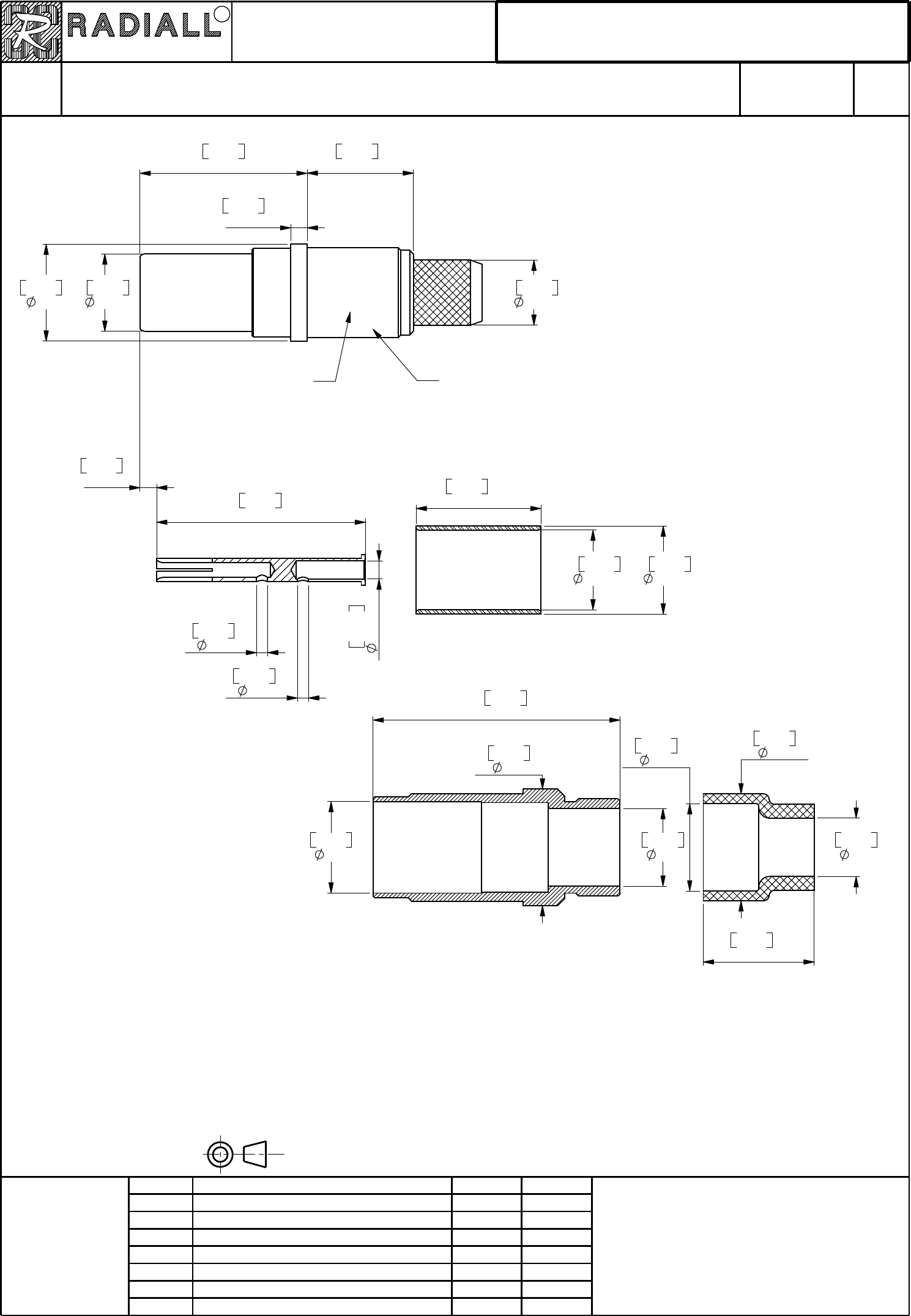
OUTER CONTACT SUBASSEMBLY
CENTER CONTACT
FERRULE
SEALING BOOT
INTERMEDIATE SEALING BOOT
MATERIAL AND FINISH :
CENTER CONTACT : BERYLIUM COPPER_GOLD OVER NICKEL PLATED
OUTER CONTACT AND FERRULE : COPPER ALLOY_GOLD OVER NICKEL PLATED
INSULATOR : PTFE
SEALING BOOT : FLUOROSILICONE ELASTOMERE
INTERMEDIATE SEALING BOOT : THERMOPLASTIC BLUE COLOR
TOOLING
INSERTION / EXTRACTION TOOL : M8 1969/28-01
CENTER CONTACT : CRIMPING TOOL : M22520/2-01 (RADIALL 282 281)
POSITIONER : 282 581 008 SELECTOR 7
OUTER CONTACT BODY : M22520/5-01 ( RADIALL 282 293)
DIE : M22520/5-45 HEX B 0.218 ON FLATS
RADIALL
- - - -
BACC47FTOG
Black ink
Date code
Page
PagePage
Page
Issue:
Issue:Issue:
Issue:
TECHNICAL DATA SHEET
TECHNICAL DATA SHEETTECHNICAL DATA SHEET
TECHNICAL DATA SHEET
Issue
IssueIssue
Issue Revisions
RevisionsRevisions
Revisions Approved
ApprovedApproved
Approved
4112_9311
4112_9311
4112_9311
4112_9311
617 108
617 108617 108
617 108
SIZE 5 COAXIAL CRIMP PIN CONTACT
SIZE 5 COAXIAL CRIMP PIN CONTACTSIZE 5 COAXIAL CRIMP PIN CONTACT
SIZE 5 COAXIAL CRIMP PIN CONTACT
FOR 0G CABLES.
FOR 0G CABLES.FOR 0G CABLES.
FOR 0G CABLES.
Spl BOEING.
Spl BOEING.Spl BOEING.
Spl BOEING.
617108EN
617108EN617108EN
617108EN
Series
SeriesSeries
Series
EPXA
EPXAEPXA
EPXA
APPR.:
APPR.:APPR.:
APPR.:
DATE:
DATE:DATE:
DATE:
NOM:
NOM:NOM:
NOM:
PEN:
PEN:PEN:
PEN:
CREATION
CREATIONCREATION
CREATION
M0000400022A
M0000400022AM0000400022A
M0000400022A
MOYON S.
MOYON S.MOYON S.
MOYON S.
14 02 2001
14 02 200114 02 2001
14 02 2001
Name
NameName
Name
This information is given as an indication.In the continual goal to improve our products,we reserve the right to make any modifications judged necessary.
This information is given as an indication.In the continual goal to improve our products,we reserve the right to make any modifications judged necessary.
This information is given as an indication.In the continual goal to improve our products,we reserve the right to make any modifications judged necessary.
This information is given as an indication.In the continual goal to improve our products,we reserve the right to make any modifications judged necessary.
MULTICONTACT CONNECTORS
MULTICONTACT CONNECTORSMULTICONTACT CONNECTORS
MULTICONTACT CONNECTORS
R
VAN DEN B.
VAN DEN B.VAN DEN B.
VAN DEN B.
DIMENSIONS : mm (inch) -
DIMENSIONS : mm (inch) -DIMENSIONS : mm (inch) -
DIMENSIONS : mm (inch) -
1/3
1/31/3
1/3
Oct. 31, 2005
Oct. 31, 2005Oct. 31, 2005
Oct. 31, 2005
Jun 06 01Marking and wiring update Moyon
BVDM
Moyon
Abr 27 01 Added wiring instructions
BVDM
Moyon
Added marking and tooling
Mar 27 01
Feb 01 02
BVDM
Moyon
Wiring instruction modification BVDM
Material modification Moyon
Apr 17,02 BVDM
May 14, 03 Add. of Ø 0,8 + 6,6 + 5,6 + 6,3 and 4,2. L.Garcia C.Lahoreau
EPXB
EPXBEPXB
EPXB
Oct 31, 05 Modif. of center and outer contacts material. L.Garcia L.Giet
4.5
[0.177]
14
[0.551]
5
[0.197]
Sealing boot
Intermediate sealing boot
Insulator
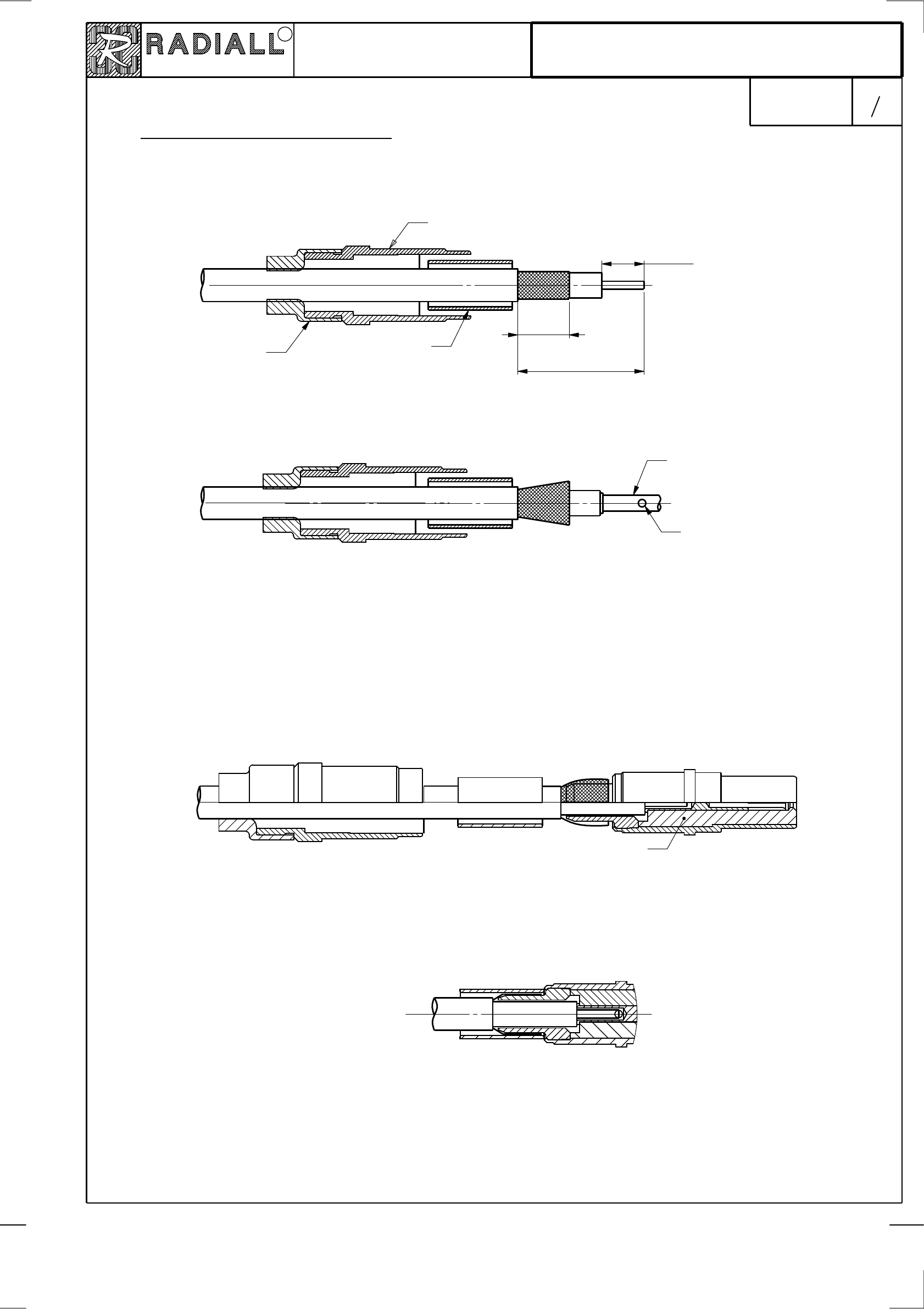
- Fold back the braid over crimp barrel
- Slide the ferrule until it buts against the shoulder of the crimp barrel
WIRING INSTRUCTIONS :
WIRING INSTRUCTIONS :WIRING INSTRUCTIONS :
WIRING INSTRUCTIONS :
- Put the sealing boots and the ferrule over the coax cable, before stripping
- Strip cable as shown
- Flair the braid
- Crimp center contact on the center conductor
- Make sure that you can see the conductor strands through the inspection hole in the center contact.
- Crimp with :
- tool : M22520/2-01 RADIALL 282 281
- Positioner : RADIALL 282 581 008
- Selector : 7
- Push the cable and center contact assembly into the outer contact assembly until
it butts against the insulator
- Crimp with :
Tool : M22520/5-01 (RADIALL 282 293)
Die : M22520/5-45 Hex B 0.218 on flats
Ferrule
Center contact
Inspection hole
Page
PagePage
Page
Issue:
Issue:Issue:
Issue:
TECHNICAL DATA SHEET
TECHNICAL DATA SHEETTECHNICAL DATA SHEET
TECHNICAL DATA SHEET
4112_9311
4112_9311
4112_9311
4112_9311
617 108
617 108617 108
617 108
Oct. 31, 2005
Oct. 31, 2005Oct. 31, 2005
Oct. 31, 2005 2
22
2
A617108
A617108A617108
A617108
This information is given as an indication.In the continual goal to improve our products,we reserve the right to make any modifications judged necessary.
This information is given as an indication.In the continual goal to improve our products,we reserve the right to make any modifications judged necessary.
This information is given as an indication.In the continual goal to improve our products,we reserve the right to make any modifications judged necessary.
This information is given as an indication.In the continual goal to improve our products,we reserve the right to make any modifications judged necessary.
MULTICONTACT CONNECTORS
MULTICONTACT CONNECTORSMULTICONTACT CONNECTORS
MULTICONTACT CONNECTORS
R
3
33
3

30 min.
[1.181]
SETTING UP THE COAX CONTACT INTO THE INSERT :
SETTING UP THE COAX CONTACT INTO THE INSERT :SETTING UP THE COAX CONTACT INTO THE INSERT :
SETTING UP THE COAX CONTACT INTO THE INSERT :
- Slide the sealing boot schoulder against the intermediate sealing boot
Intermediate sealing boot schoulder against the rear face of the grommet
- Putt in place the coax contact and locked it into the insert.
- Slide the intermediate sealing boot on the cable until the schoulder butts against the rear
face of the grommet.
- Before introducing the coax contact into the insert make sure that the intermediate sealing
boot is at 30mm [1.181] min. from the front of the coax contact.
Intermediate sealing boot schoulder
- Before introducing the coax contact into the insert make sure that the intermediate sealing
boot is at 30mm [1.181] min. from the front of the coax contact.
Intermediate sealing boot schoulder
Page
PagePage
Page
Issue:
Issue:Issue:
Issue:
TECHNICAL DATA SHEET
TECHNICAL DATA SHEETTECHNICAL DATA SHEET
TECHNICAL DATA SHEET
4112_9311
4112_9311
4112_9311
4112_9311
617 108
617 108617 108
617 108
Oct. 31, 2005
Oct. 31, 2005Oct. 31, 2005
Oct. 31, 2005 3/3
3/33/3
3/3
617108EN
617108EN617108EN
617108EN
This information is given as an indication.In the continual goal to improve our products,we reserve the right to make any modifications judged necessary.
This information is given as an indication.In the continual goal to improve our products,we reserve the right to make any modifications judged necessary.
This information is given as an indication.In the continual goal to improve our products,we reserve the right to make any modifications judged necessary.
This information is given as an indication.In the continual goal to improve our products,we reserve the right to make any modifications judged necessary.
MULTICONTACT CONNECTORS
MULTICONTACT CONNECTORSMULTICONTACT CONNECTORS
MULTICONTACT CONNECTORS
R
