Radiation Safety and Control Services DMCTD2K Simulated Radiation Detection Instrument User Manual Exhibit D Users Manual per 2 1033 b3
Radiation Safety & Control Services, Inc. Simulated Radiation Detection Instrument Exhibit D Users Manual per 2 1033 b3
Exhibit D Users Manual per 2 1033 b3

DMC 2000TD
OPERATORS MANUAL
Radiation Safety & Control Services, Inc
91 Portsmouth Avenue
Stratham, NH 03885-2468
1-800-525-8339
(603) 778-2871 (Outside USA)
www.radsafety.com
December 2014

DMC 2000TD OPERATORS MANUAL
Note: For ease of use and consistency in user instruction, portions of this manual directly reference the
standard DMC 2000S User’s Manual published by Mirion Technologies. For instruction in the use of the
standard DMC 2000S only those manuals approved by Mirion Technologies should be used.
GLOSSARY
/h or /hr
Per hour
°C
Degrees Celsius
°F
Degrees Fahrenheit
Active Device
A device currently connected to a TCU and actively being controlled or observed by the user.
Broadcast Group
Multiple devices combined into a single controllable group on the TCU. Allows the user to send
the same commands to all devices simultaneously.
dB(A)
Decibels – ‘A’ weighted scale (sound intensity)
DMC
DMC 2000 Electronic Dosimeter
DMC 2000TD
DMC 2000 Training Device
Dose
The accumulated dose to which alarm thresholds apply.
EEPROM
Electrically Erasable Programmable Read Only Memory
EMI
Electromagnetic Interference
H10
DMC and DMC 2000TD LCD nomenclature for personal dose (Hp(10))
H07
DMC and DMC 2000TD LCD nomenclature for personal dose (Hp(07))
H10/h
DMC and DMC 2000TD LCD nomenclature for personal dose rate (Hp(10))
H07/h
DMC and DMC 2000TD LCD nomenclature for personal dose rate (Hp(07))
LCD
Liquid Crystal Display
LED
Light Emitting Diode
LTC
Lithium Thionyl Chloride (Sulphurous Oxychloride, SOCI2)
m
meter/milli
mm
millimeter
PCB
Printed Circuit Board
ppm
Parts per million
RAM
Random Access Memory
rem
A unit of dose equivalent
RFI
Radio Frequency Interference
SDE
Shallow Dose Equivalent (alternative nomenclature for Hp(0.07))
Short-press
A short press and release of the DMC 2000TD button
Soft Button
The two keypad buttons located directly below the LCD of the TCU. Each button is capable of
accessing different TCU functions. The current function of the button will be displayed on the
LCD directly above.
Standby Device
A device currently connected to a TCU but not actively being controlled by the user.
Sv
Sievert, SI unit of dose equivalent
TCU
Training Control Unit
User ID
A numeric code of up to 6 digits that may be written to the DMC to define the current user or
wearer
Wearer ID
Alternative terminology for the User ID
Wearer Name
Alternative terminology for the User Name
i REVISION 0

DMC 2000TD OPERATORS MANUAL
SAFETY PRECAUTIONS
Battery Warnings
Batteries are susceptible to fire and abuse. Some manufactures provide batteries with a safety vent,
which allows a controlled released of electrolyte if fire and abuse conditions occur. If the DMC 2000TD
has been damaged in a manner that could affect the battery, care must be exercised during battery
removal. The battery may have vented into the DMC 2000TD case and caused the DMC 2000TD to
become pressurized.
Internal Access
The operator is not authorized to open the DMC 2000TD. Attempting to gain access to the internal
components beyond changing the battery will cause permanent damage to the DMC 2000TD
electronics.
iii REVISION 0

DMC 2000TD OPERATORS MANUAL
FCC Compliance Statement
This device complies with Part 15 of the FCC Rules. Operation is subject to the following two conditions:
(1) this device may not cause harmful interference, and (2) this device must accept any interference
received, including interference that may cause undesired operation.
Important
Changes or modifications to this product not authorized by Radiation Safety & Control Services, Inc.
could void the electromagnetic compatibility and wireless compliance and negate your authority to
operate the product.
Canada, Industry Canada (IC) Notices
This product complies with Industry Canada RSS-210.
This device complies with Industry Canada license-exempt RSS standard(s). Operation is subject to the
following two conditions: (1) this device may not cause interference, and (2) this device must accept any
interference, including interference that may cause undesired operation of the device.
Under Industry Canada regulations, the radio transmitter(s) in this device may only operate using an
antenna of a type and maximum (or lesser) gain approved for the transmitter by Industry Canada. To
reduce potential radio interference to other users, the antenna type and its gain should be so chosen
that the equivalent isotropically radiated power (e.i.r.p.) is not more than that necessary for successful
communication.
Canada, avis d’Industry Canada (IC)
Cet appareil est conforme aux norme RSS210 d’Industrie Canada.
Cet appareil est conforme aux normes d’exemption de licence RSS d’Industry Canada. Son
fonctionnement est soumis aux deux conditions suivantes : (1) cet appareil ne doit pas causer
d’interférence et (2) cet appareil doit accepter toute interférence, notamment les interférences qui
peuvent affecter son fonctionnement.
Conformément aux réglementations d'Industry Canada, les émetteurs radio de cet appareil ne peuvent
fonctionner qu’à l’aide d'une antenne dont le type et le gain maximal (ou minimal) pour ces émetteurs -
transmetteurs sont approuvés par Industry Canada. Pour réduire le risque d’interférence éventuelle
pour les autres utilisateurs, le type et le gain de l’antenne doivent être choisis de manière à ce que la
puissance isotrope rayonnée équivalente (p.i.r.e.) minimale nécessaire à une bonne communication soit
fournie.
v REVISION 0

DMC 2000TD OPERATORS MANUAL
Contents
1 Introduction ............................................................................................................................................... 1
1.1 Brief Description of RSCS Simulation System Architecture ................................................................ 1
1.2 Simulation Control Center .................................................................................................................. 1
1.3 DMC 2000S Training Device ................................................................................................................ 1
1.4 Items Supplied..................................................................................................................................... 1
1 DMC 2000TD .............................................................................................................................................. 3
1.5 DMC 2000TD Major Characteristics .................................................................................................... 3
1.6 Preparation for Use/Getting Started .................................................................................................. 5
1.6.1 Setting Up ..................................................................................................................................... 5
1.7 Functional Description and Operating Instructions ............................................................................ 8
1.7.1 Wireless Network Configuration .................................................................................................. 8
1.8 DMC 2000TD Functional Description and Operation ......................................................................... 8
1.8.1 DMC 2000TD LCD Display ............................................................................................................ 8
1.9 Operating Modes ................................................................................................................................ 9
1.9.1 Autonomous Mode ...................................................................................................................... 9
1.9.2 Satellite Mode .............................................................................................................................. 9
1.9.3 DMC 2000TD Function Mode ....................................................................................................... 9
1.9.4 Off Mode .................................................................................................................................... 10
1.9.5 Pause Mode ............................................................................................................................... 10
1.9.6 Active/Measurement Mode....................................................................................................... 10
1.10 Start-Up ........................................................................................................................................... 10
1.10.1 Satellite Mode .......................................................................................................................... 11
1.10.2 Stand-Alone Mode ................................................................................................................... 11
1.11 Operation in Satellite Mode ............................................................................................................ 11
1.11.1 Switching to Active Mode ........................................................................................................ 11
1.11.2 Operation in Active Mode ........................................................................................................ 12
1.11.3 Operation in Pause Mode ........................................................................................................ 16
1.12 Alarms ............................................................................................................................................. 19
1.12.1 Simulated Dose Pre-Alarm ....................................................................................................... 19
1.12.2 Simulated Dose Alarm .............................................................................................................. 20
1.12.3 Simulated Dose Rate Alarm ..................................................................................................... 21
1.12.4 Simulated Duration Alarm ....................................................................................................... 21
vii REVISION 0

DMC 2000TD OPERATORS MANUAL
1.13 Simulated Faults .............................................................................................................................. 22
1.13.1 Blank Screen ............................................................................................................................. 22
1.13.2 Integrated Circuit Fault ............................................................................................................ 22
1.13.3 Initialization Fault ..................................................................................................................... 22
1.13.4 E2PROM Fault .......................................................................................................................... 23
1.13.5 Detector Fault .......................................................................................................................... 23
1.13.6 Historical Fault ......................................................................................................................... 23
1.13.7 Calibration Fault ....................................................................................................................... 24
1.13.8 Defective Battery Fault ............................................................................................................ 24
1.13.9 Low Battery Fault ..................................................................................................................... 24
1.14 Non-Simulated Faults ...................................................................................................................... 25
1.15 Maintenance ................................................................................................................................... 26
1.15.1 The DMC 2000TD Battery ........................................................................................................ 26
1.15.2 Replacement Batteries ............................................................................................................. 26
1.15.3 Cleaning .................................................................................................................................... 26
1.15.4 General Cleaning ...................................................................................................................... 26
1.15.5 Cleaning after a Battery Leakage ............................................................................................. 26
1.15.6 Periodic Cleaning...................................................................................................................... 26
1.16 Shipping and Storage Precautions .................................................................................................. 27
2 Simulation Control Center ....................................................................................................................... 29
2.1 Introduction ...................................................................................................................................... 29
2.2 Functional Description ...................................................................................................................... 29
2.2.1 General ....................................................................................................................................... 29
2.2.2 Hub Page .................................................................................................................................... 29
2.2.3 Preparations for Use .................................................................................................................. 29
2.3 Operating Instructions ...................................................................................................................... 30
2.3.1 Starting the Simulation Control Center Application .................................................................. 30
2.3.2 Device Configurations ................................................................................................................ 30
2.3.3 Connecting to Available DMC 2000TDs ..................................................................................... 39
2.3.4 Controlling Connected DMC 2000TDs ....................................................................................... 42
REVISION 0 viii

DMC 2000TD OPERATORS MANUAL
List of Figures
Figure 1 DMC 2000TD Controls and Indicators ............................................................................................. 4
Figure 2 External View with Battery Removed ............................................................................................. 6
Figure 3 Wearing the DMC 2000TD .............................................................................................................. 7
Figure 4 DMC 2000TD LCD Display ............................................................................................................... 9
Figure 5 DMC 2000TD LCD Display Indication .............................................................................................. 9
Figure 6 DMC 2000TD in Measurement Mode ........................................................................................... 12
Figure 7 Dose Equivalent Measurement Display ........................................................................................ 12
Figure 8 Time Display .................................................................................................................................. 12
Figure 9 Display of Dose Rate in Measurement Mode ............................................................................... 13
Figure 10 Simulated Dose Equivalent Saturation Display ........................................................................... 13
Figure 11 Dose Equivalent Rate Saturation Display .................................................................................... 13
Figure 12 Example of Fault/Alarm Indicator ............................................................................................... 13
Figure 13 Simulated "Dose" Alarm Threshold Display ................................................................................ 14
Figure 14 Simulated "Rate" Alarm Threshold Display................................................................................. 14
Figure 15 Simulated "Time" Alarm Threshold Display ................................................................................ 14
Figure 16 Simulated "Dose" Pre-Alarm Threshold Display ......................................................................... 15
Figure 17 Simulated "Rate" Pre-Alarm Threshold Display .......................................................................... 15
Figure 18 Pause Mode Displays .................................................................................................................. 15
Figure 19 Low Battery Condition ................................................................................................................ 16
Figure 20 Fault Condition in Pause Mode Display ...................................................................................... 16
Figure 21 DMC 2000TD Display in Pause Mode .......................................................................................... 17
Figure 22 DMC 2000TD Display of Operating Mode ................................................................................... 17
Figure 23 DMC 2000TD Simulated Cumulative Dose Display ..................................................................... 17
Figure 24 DMC 2000TD Simulated Rate Display ......................................................................................... 17
Figure 25 DMC 2000TD Simulated Dose Alarm Threshold Display ............................................................. 17
Figure 26 DMC 2000TD Simulated Rate Alarm Threshold Display ............................................................. 18
Figure 27 DMC 2000TD Simulated Dose Pre-Alarm Threshold Display ...................................................... 18
Figure 28 DMC 2000TD Simulated Rate Pre-Alarm Threshold Display ....................................................... 18
Figure 29 DMC 2000TD Audible Alarm Operating Mode Display ............................................................... 18
Figure 30 DMC 2000TD Simulated Serial Number Display ......................................................................... 19
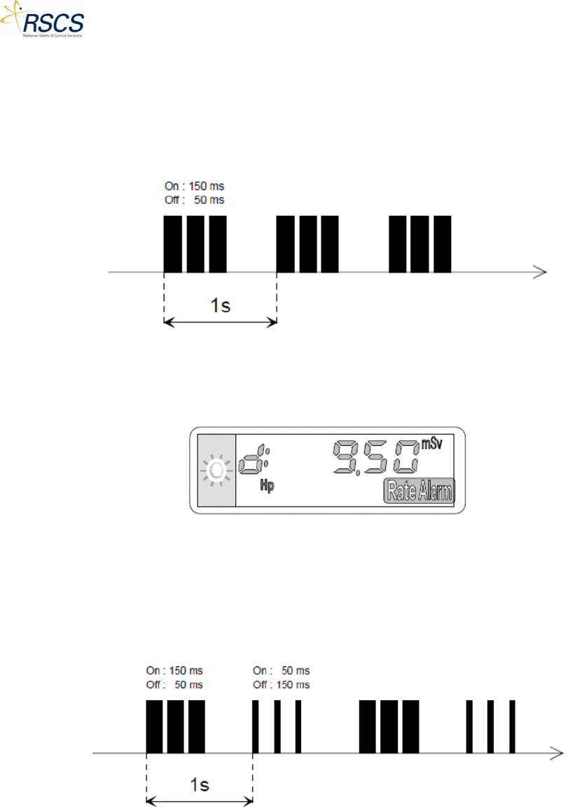
Figure 31 Simulated Dose Pre-Alarm Sound ............................................................................................... 19
Figure 32 Simulated Dose Pre-Alarm Display ............................................................................................. 20
Figure 33 Simulated Dose Pre-Alarm and Rate Pre-Alarm Sound .............................................................. 20
Figure 34 Simulated Dose Alarm Sound...................................................................................................... 20
Figure 35 Simulated Dose Alarm Display .................................................................................................... 20
Figure 36 Simulated Dose Rate Alarm Sound ............................................................................................. 21
Figure 37 Simulated Dose Rate Alarm Display ............................................................................................ 21
Figure 38 Simulated Dose Rate Alarm and Dose Alarm Sound ................................................................... 21
Figure 39 Simulated Duration Alarm Display .............................................................................................. 22
Figure 40 Simulated Blank Screen Fault ...................................................................................................... 22
Figure 41 Simulated Integrated Circuit Fault Display ................................................................................. 22
Figure 42 Simulated Initialization Fault Display .......................................................................................... 23
ix REVISION 0

DMC 2000TD OPERATORS MANUAL
Figure 43 Simulated E2PROM Fault Display ................................................................................................ 23
Figure 44 Simulated Detector Fault Display and Sound ............................................................................. 23
Figure 45 Simulated Historical Fault Display ............................................................................................... 23
Figure 46 Simulated Calibration Fault Display ............................................................................................ 24
Figure 47 Simulated Defective Battery Fault Display and Sound................................................................ 24
Figure 48 Simulated Low Battery Fault Display and Sound ........................................................................ 24
Figure 49 Battery Low Fault Display............................................................................................................ 25
Figure 50 SCC Hub Page .............................................................................................................................. 29
REVISION 0 x

DMC 2000TD OPERATORS MANUAL
1 Introduction
This manual provides operation and operator’s maintenance information for the Radiation Safety &
Control Services Inc. (RSCS) DMC 2000S Training Device (DMC 2000TD). The DMC 2000TD is a fully
functioning simulated replica of the Mirion Technologies (MGP Instruments) DMC 2000S Electronic
Dosimeter. The manual provides both instruction for the DMC 2000TD and the Simulation Control
Center (SCC) software used to wirelessly control the DMC 2000TD. It is meant for the trainer’s reference
and should not be used in place of the standard DMC 2000 manual. It is strongly suggested that both the
trainer and trainee fully familiarize themselves with the standard DMC 2000 manual before reading this
manual.
1.1 Brief Description of RSCS Simulation System Architecture
The most basic level of the simulation system developed by RSCS Inc. consists of the Simulation Control
Center (SCC) software, operating on a tablet with a USB Dongle installed, and at least one simulated
training device. The SCC software and training device communicate with each other wirelessly over a
proprietary IEEE 802.15.4 network through the USB Dongle. This communication allows a training
instructor to remotely control simulated gamma radiation levels as observed by a trainee operating the
connected device.
The simulation system provides for the interoperability of multiple control devices and training devices
to be used in close proximity. Any SCC software application is capable of controlling one or more training
instruments. This flexibility allows one or more instructors to instruct multiple students using different
training instruments simultaneously. Once a device has been connected to a specific control device it
may no longer be seen by or connected to another SCC application even if another is within range, until
the control device has released control.
1.2 Simulation Control Center
The Simulation Control Center (SCC) software application was developed to run on any Windows 8.1TM
tablet or computer. Combined with the provided USB Dongle the SCC allows a training instructor to
remotely observe and send commands to multiple DMC 2000TDs simultaneously. In addition to
remotely controlling simulators SCC allows the user to configure specific device settings and update
device firmware.
1.3 DMC 2000S Training Device
The DMC 2000S Training Device (DMC 2000TD) is a fully functioning simulated DMC 2000S personal
electronic dosimeter that is capable of simulating almost all of the major features and functions of the
standard DMC 2000S. It may be configured by the user to match almost any configuration used in the
standard DMC 2000S.
1.4 Items Supplied
The DMC 2000TD may be supplied individually for use with existing Windows 8.1TM computers or
Tablets, or with a preconfigured tablet. If the DMC 2000TD is supplied without a Windows 8.1TM tablet,
the user must download the SCC application from the Windows App StoreTM. In addition to the SCC
application the system requires the use of an RSCS, Inc. supplied USB Dongle for communication
purposes.
1 REVISION 0

DMC 2000TD OPERATORS MANUAL
1 DMC 2000TD
1.5 DMC 2000TD Major Characteristics
The DMC 2000TD has been designed to match both the environmental and electrical characteristics of
the standard DMC 2000S as closely as possible. Therefore, it has been designed for use in the following
environments:
• Office and Laboratory environments
• Industrial environments
• Hospitals
• Military environments (including dockyards and shipping – excluding exposure to salt water and
extremes in military environments.
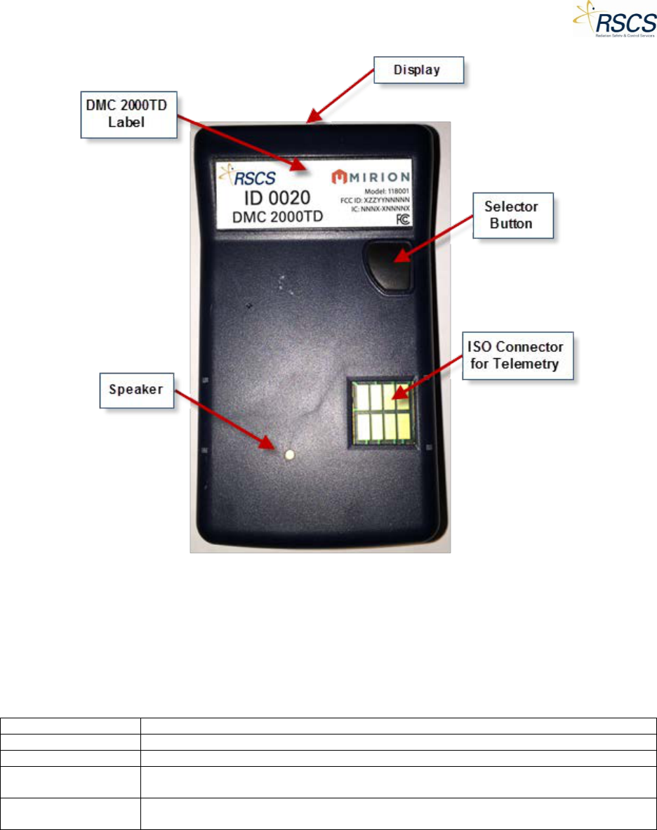
The major physical characteristics of the DMC 2000TD are listed in Table 1. External features are shown
in Figure 1 and outlined in Table 2.
Table 1 DMC 2000TD Major Characteristics
Item
Characteristic
Model Number
DMC 2000TD
Weight (lbs./kg)
0.1235/0.056
Height (in/mm)
3.41/86.5
Width (in/mm)
1.89/48
Depth (in/mm)
0.35/9 (0.67/17 at the display)
Volume (in3/cm3)
85-90 dBa at 30 cm
Alarm Sounder
DMC 2000TD
3 REVISION 0
DMC 2000TD OPERATORS MANUAL
Figure 1 DMC 2000TD Controls and Indicators
The DMC 2000TD also has the following additional major features:
• Manufactured using original Mirion Technologies (MGPI) mechanical components.
• Wireless communication via built in 802.15.4 transmitter with a range of approximately 75 ft.
Table 2 DMC 2000TD Electrical and Wireless Information
Item
Characteristic
Power Requirements
One (1) LiMnO2 / 3V/ CR 2450
Battery Life
Up to 30 hours depending upon feature configuration, connection to SCC and alarm use.
Wireless
Communication
2.4 GHz, 18 mW
Range of Operation
Minimum of 75 ft. line of sight. Depending upon material composition obstructions may reduce
operational distance.
REVISION 0 4

DMC 2000TD OPERATORS MANUAL
1.6 Preparation for Use/Getting Started
The following section describes the general process for setting up the DMC 2000TD for use. For specific
instructions on preparing the SCC application for use see section 2.2.3.
1.6.1 Setting Up
The initial set up process for the DMC 2000TD is very simple and almost exactly the same as that used
for the standard DMC 2000S. Setting up is primarily composed of:
• Unpacking the DMC 2000TD
• Inserting the battery (if not already installed)
• Checking the initialization sequence
• Checking the default settings
Unpacking the DMC 2000TD
There are no special unpacking instructions. Depending upon customer requirements the DMC 2000TD
may, or may not be shipped with a battery and/or clip assembly. The battery, if supplied will be a 3 V
CR2450 Lithium battery.
The DMC 2000TD Battery
WARNING
Keep away from small children. Do not swallow. Not rechargeable. Do not throw in fire.
General Instructions and Precautions
Always use new undamaged batteries of the correct type.
Inserting/Replacing the DMC 2000TD Battery
The DMC 2000TD is supplied with the standard Mirion Technologies (MGPI) battery cover. Therefore,
the same battery installation/removal procedure as the standard DMC 2000S should be used.
1. Read and observe the General Precautions and instructions at the beginning of this section. If
necessary remove the battery cap from the case as described in steps 2 through 8 below.
2. Switch the DMC 2000TD to *Off*.
3. Remove the DMC 2000TD clip if attached.
4. Using a standard DMC 2000S battery key (or if unavailable, using a screwdriver), unscrew
(counterclockwise) the battery cover.
5. Take Off the battery cover and remove the battery.
Note: Due to the presence of a capacitor to maintain power during battery removal, the DMC 2000TD
LCD will display *Off* for a period of time even after battery removal. Once the capacitor has dissipated,
the LCD will clear.
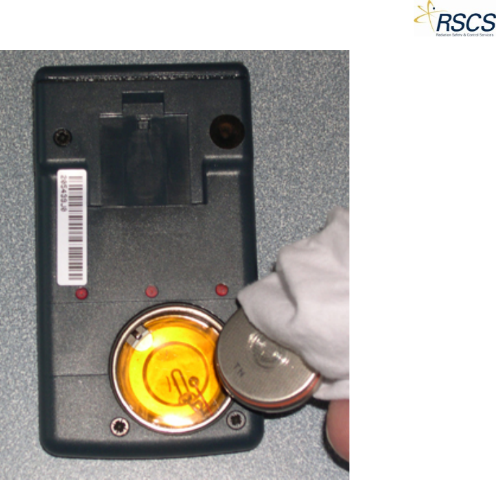
6. Take a piece of cotton cloth to handle the battery, in order to avoid the superficial oxidation of
the housing stainless steel or the cover.
7. Insert a new battery in the housing (with the “+” side of the battery placed towards the front of
the dosimeter).
Note: Use caution not to over torque the battery cover. Hand tight plus ¼ turn is recommended.
5 REVISION 0
DMC 2000TD OPERATORS MANUAL
Figure 2 External View with Battery Removed
Start-up Sequence
Due to the constraints of simulation, the DMC 2000TD has a modified version of the DMC 2000’s
“Pause” Mode. After battery replacement, the DMC 2000TD will display “*Off*” instead of the DMC
2000’s “Pause”.
Initial Battery Insertion or the “Off” State
When a battery is inserted into the DMC 2000TD for the first time or when the unit is in the powered
down state, indicated by “*Off*” on the LCD, insertion of a new battery will not be indicated in a
manner other than the LCD displaying or continuing to display “*Off*”.
Battery Changes in the “On” State
When changing the battery while the DMC 2000TD is in the “On” state, upon loss of battery contact, the
DMC 2000TD will activate the “batlo” alarm until a battery regains contact or the capacitor dissipates
completely. Once the battery is replaced, the DMC 2000TD will display “*Off*” and no longer be in “On”
state.
Wearing a DMC 2000TD
The DMC 2000TD should be worn in the same manner as the standard DMC 2000S to ensure proper
training. For most operating conditions, it is recommended that the DMC 2000TD be worn on the
outside of any protective clothing (see Figure 3). Note that the button should be facing outwards.
REVISION 0 6

DMC 2000TD OPERATORS MANUAL
Similar to the standard DMC 2000S, wearing the DMC 2000TD outside of protective clothing offers the
advantage of allowing the user to read the DMC 2000TD’s LCD display and operate the button as
required. Typically, the DMC 2000TD should be worn on the chest or the waist. The type of outer
protective clothing will determine how the DMC 2000TD is attached (i.e. the DMC 2000TD clip or a
lanyard). For example, if the protective clothing has no breast pocket (or the use of a belt is prohibited)
the lanyard may be the most practical method of wearing the DMC 2000TD.
Figure 3 Wearing the DMC 2000TD
7 REVISION 0

DMC 2000TD OPERATORS MANUAL
1.7 Functional Description and Operating Instructions
The following chapter explains the basic functions performed by the DMC 2000TD and the functions of
the SCC software application when used to control the DMC 2000TD. It also instructs both the trainer
and the trainee in the functions that will allow them to send commands from SCC, display data on
devices, acknowledge alarms and general operation of each device. For basic functions and operations
of SCC, please refer to Chapter 2
The chapter has the following two sections:
• Wireless Network Configuration
• DMC 2000TD Functional Description and Operation
1.7.1 Wireless Network Configuration
This section provides a brief technical overview of the current network configuration used by the SCC
software application and the associated simulators. It explains the two basic options available for
controlling DMC 2000TDs and other simulators remotely using the SCC application. The two basic
options when using the network are:
• Normal Mode
• Group Mode
A basic understanding of these wireless network configurations and the functions of each device within
the network allows an instructor to configure the training methods and scenarios to provide the most
realistic training possible.
Normal Mode
The Normal Mode is the basic means of controlling and interacting with a single training device or
multiple training devices all being controlled individually, or simultaneously, depending upon trainer
preference. It is the default option when searching for and connecting to a device using the SCC. This
mode allows the trainer to continuously adjust the connected device(s) measurement values, activate
simulated alarms and other features, as well as monitor the current status indications being displayed
on the device(s).
Group Mode
Group Mode incorporates all the features of Individual Control Mode while allowing SCC to provide the
same control inputs to different groups of multiple training devices at the same time. This mode allows
the trainer to create groups of devices and provide the same inputs, e.g. dose rate levels, to all the
devices within a group at once. SCC is capable of connecting and controlling up to thirty-two (32)
different devices at one time. This total may be reached in any manner the instructor chooses so long as
the number of controlled units does not exceed thirty-two (32).
1.8 DMC 2000TD Functional Description and Operation
1.8.1 DMC 2000TD LCD Display
The same custom-designed LCD display as the standard DMC 2000S is used by the DMC 2000TD. This
display provides a visual interface for viewing simulated dose and other simulated DMC data. The DMC
2000TD display is illustrated in Figure 4.
REVISION 0 8
DMC 2000TD OPERATORS MANUAL
Figure 4 DMC 2000TD LCD Display
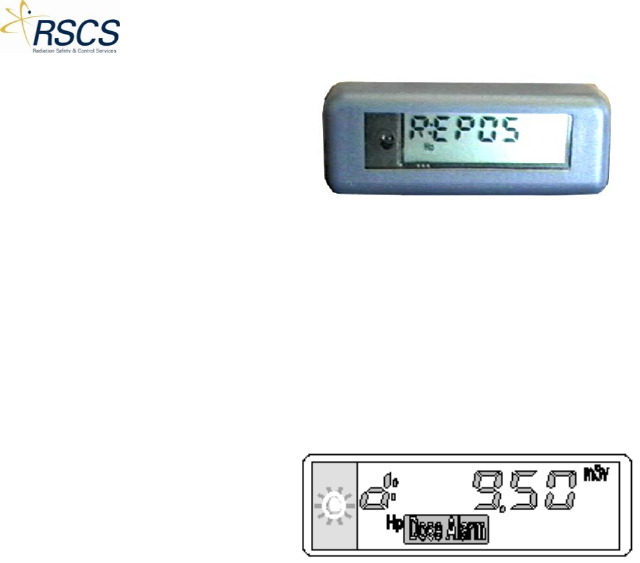
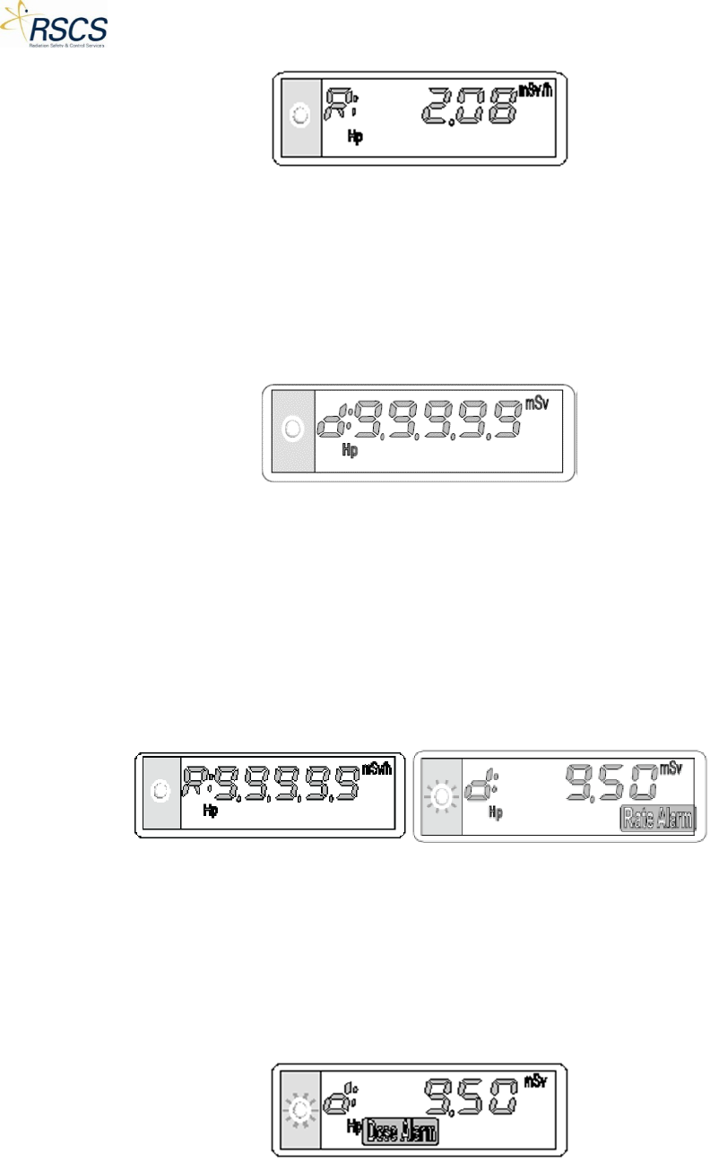
Figure 5 illustrates the display indicating a dose alarm (the alarm threshold programmed into the DMC
2000TD for the simulated dose equivalent has been exceeded).
• The indicator light flashes
• The “dose alarm” indicator flashes
• The value of the dose is displayed (9.5 mSv)
Figure 5 DMC 2000TD LCD Display Indication
1.9 Operating Modes
The DMC 2000TD retains the same operating modes as the standard DMC 2000S. The DMC 2000TD can
be used in two different operating modes: the “autonomous” mode and the “Satellite” Mode.
The mode selection can be set using the DMC 2000TD Configurations feature of SCC (see 2.3.2).
1.9.1 Autonomous Mode
In Autonomous mode, the DMC 2000TD is capable of entering and exiting Active Mode without the use
of the SCC application.
1.9.2 Satellite Mode
In Satellite Mode, the DMC 2000TD enters Measurement Mode via the SCC application. All configured
functions are controlled by the SCC application.
1.9.3 DMC 2000TD Function Mode
Regardless of the operating mode, the DMC 2000TD has various function modes.
• Off
• Pause
• Active/Measurement
9 REVISION 0

DMC 2000TD OPERATORS MANUAL
1.9.4 Off Mode
When in this mode, the DMC 2000TD:
• Permanently displays the message “*Off*”.
• Periodically monitors the battery status.
In this mode the DMC 2000TD uses minimal power consumption. No simulation functions or SCC
connections are available in this configuration.
1.9.5 Pause Mode
When in this mode, the DMC 2000TD:
• Periodically monitors the battery status
• Permanently displays the message “Pause” or a personalized message of 6 characters or less if
configured
• Attempts to connect with any available Control Devices (if unconnected)
In this mode the DMC 2000TD simulates all the selected features and functions of a standard DMC
2000S Pause Mode operation. During this state the DMC 2000TD does not accumulate dose and allows
for limited changes initiated from the SCC application. All networking and major functions of the SCC
application are available to the trainer when in Pause Mode.
Note: The personalized message displayed in Pause Mode can be set DMC 2000TDin the SCC Device
Configuration.
1.9.6 Active/Measurement Mode
When in this mode, the DMC 2000TD:
• Communicates with the SCC application for all selected features
• Audible and Visual signals activate when commanded
• Periodically monitors the battery status
• Attempts to connect with any available Control Devices (if unconnected)
In this mode the DMC 2000TD simulates all the selected features and functions of a standard DMC
2000S Measurement Mode operation. During this state all functions of the simulator and SCC are
available to the trainer.
1.10 Start-Up
To start up a DMC 2000TD the following procedures must be performed:
• A short press of the DMC 2000TD button to exit “*Off*” mode
• Configuration using SCC Device Configurations (definition of alarm threshold values, dose rate
display authorization, alarm rate authorization, alarm duration…)
• Activation
A connection with the SCC application is required for full operation of the DMC 2000TD in all modes.
REVISION 0 10

DMC 2000TD OPERATORS MANUAL
1.10.1 Satellite Mode
In Satellite Mode, the DMC 2000TD enters Active Mode via the SCC application. All configured functions
are controlled by SCC.
1.10.2 Stand-Alone Mode
For use in stand-alone (autonomous) mode, the initialization and initial configuration must be
performed by the SCC Device Configuration prior to use (see Section 2.3.2).
Activation is carried out by using the Selector Button (refer to Figure 1).
1.11 Operation in Satellite Mode
1.11.1 Switching to Active Mode
Switching to Active Mode primarily consists of entering the DMC 2000TD into an active display mode.
Once activated, all display characteristics are dictated by the SCC application.
To enter the DMC 2000TD into Active Mode:
• Open the Simulation Control Center (SCC).
• Perform a short-press of the DMC 2000TD(s) Selector Button to exit “Off” mode and enter
“Pause” Mode.
• The number of DMC 2000TDs in Pause will be displayed in the “Available” Tile’s lower right
corner (depending upon number of DMC 2000TDs available there may be a period of time
before all are displayed).
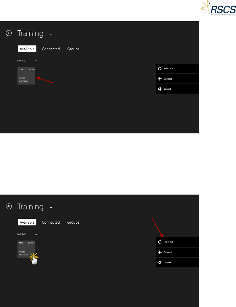
• Touch the “Available” Tile to enter the SCC Training Section.
• SCC switches to the Training Section and shows individual DMC 2000TDs as unique Tiles.
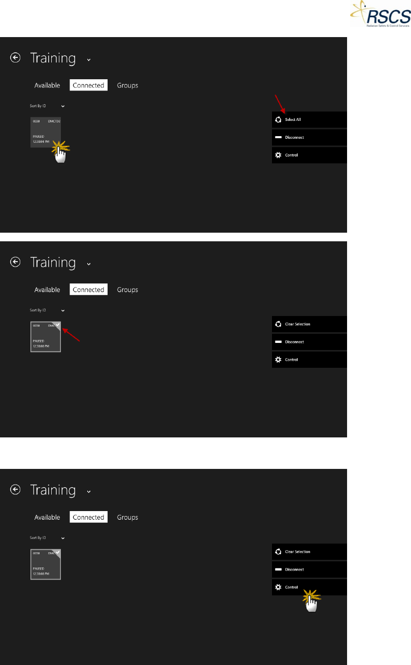
• Touch the desired DMC 2000TD Tile(s) or press Select All to select all of the available DMC
2000TDs.
Note: The DMC 2000TD Tile(s) will be highlighted once selected
Note: Once all the DMC 2000TDs are selected, the Select All option is replaced with Clear All to quickly
unselect the DMC 2000TDs if desired
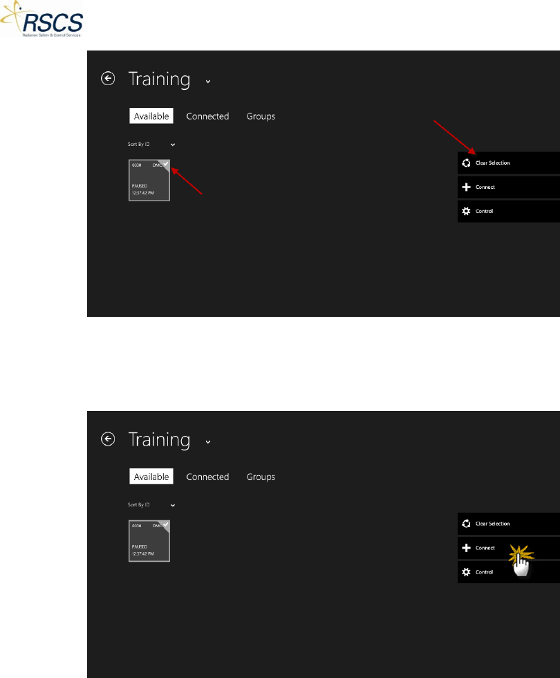
• Once the desired DMC 2000TD(s) are selected, touch the Connect button
Note: Optionally, touching the Control button will bypass the Connect step and go directly to the
Control Page
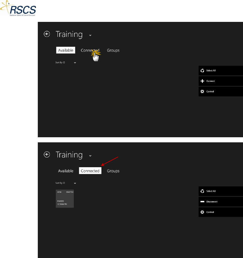
• As the DMC 2000TD(s) connect, the unique Tiles will be removed from the Available screen and
move to the Connected Page (The more devices selected the longer it will take to move all
devices to the Connected Page).
• Touch the Connected tab to move to the Connected Page.
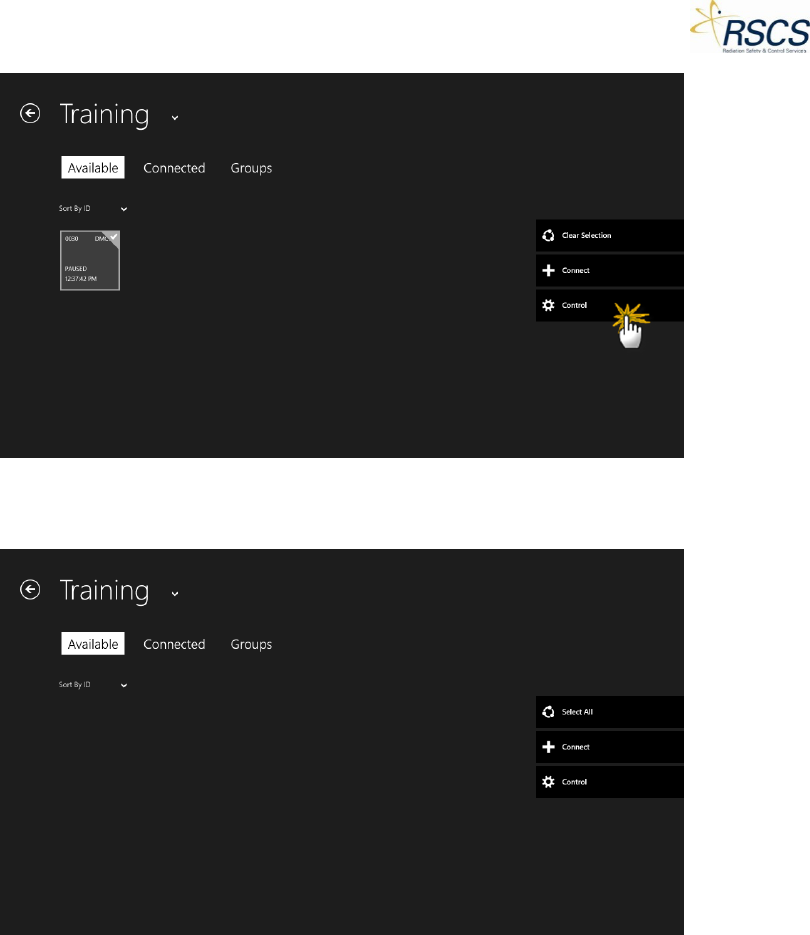
• Once on the Connected Page, select the desired DMC 2000TD(s) to control by touching the
unique DMC 2000TD Tile(s) or by touching Select All.
• Touch the Control button to begin controlling the selected DMC 2000TD(s).
• The screen will switch from the Training Section to the Control Page.
• Select the desired DMC 2000TD(s) by touching the unique DMC 2000TD Tile(s).
11 REVISION 0
DMC 2000TD OPERATORS MANUAL
Note: Alternatively, selecting all available DMC 2000TDs currently in Control is possible by swiping up
from the bottom of the screen to reveal the App Bar. Then, touch Select All to select all available DMC
2000TDs in Control
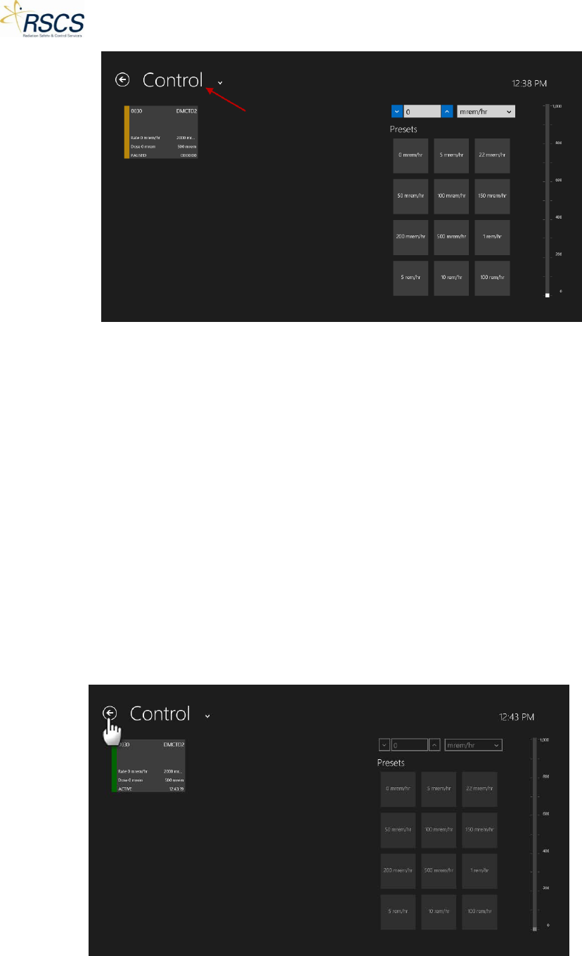
• To activate the selected DMC 2000TD(s), swipe up from the bottom of the screen to reveal the
App Bar. Then, touch Activate to put the controlled DMC 2000TD(s) in Active Mode.
• The DMC 2000TD(s) has now entered Active Mode.
• All functions besides automatic alarms are directly controlled by the SCC application.
Figure 6 DMC 2000TD in Measurement Mode
When switching to Active Mode, the display of the DMC 2000TD reads as illustrated in Figure 6.
1.11.2 Operation in Active Mode
Displaying the Simulated Dose Equivalent Measurement
When in Active Mode, the DMC 2000TD continuously displays the simulated Hp (10) dose equivalent, as
well as performing other operations.
The display shows the dose value. The unit, format (fixed or floating point) and display resolution are
selected using the DMCTD Device Configuration.
Figure 7 Dose Equivalent Measurement Display
Displaying the Time in Measurement Mode
If selected during configuration briefly pressing the Selector Button displays the time on the display.
Figure 8 Time Display
Displaying the Simulated Dose Rate Measurement
Pressing and immediately releasing the Selector Button displays the simulated dose equivalent rate
value for 30 seconds (Figure 9) after which the display returns to the dose-equivalent value display
(Figure 6). The unit, format (fixed or floating point) and display resolution are selected during device
configuration (see 2.3.2).
REVISION 0 12
DMC 2000TD OPERATORS MANUAL
Figure 9 Display of Dose Rate in Measurement Mode
Note: Other display combinations of dose/rate are available for configuration with the SCC Device
Configuration (see 2.3.2).
Simulated Dose Equivalent Saturation
When the dose equivalent exceeds the value of 999.9999 rem (9999.999 mSv), the display reads as
shown in the figure below.
Figure 10 Simulated Dose Equivalent Saturation Display
This message alternates with the measurement value, to indicate a possible dose underestimation, due
to saturation. These messages warn that the dose measured by the dosimeter may be altered by this
switching to saturation. The DMC 2000TD only simulates this condition and reverts back to normal
operation when the simulated alarm condition has been deactivated via SCC.
Simulated Dose Equivalent Rate Saturation
When the simulated dose equivalent rate exceeds the value 999.9 rem/h (9999 mSv/h) the display
alternates between the two images illustrated in the figure below.
Figure 11 Dose Equivalent Rate Saturation Display
After reducing the simulated dose equivalent rate to 999.9 rem/h or less, the display will return to
normal and the rate alarm will end.
Fault and Alarm Indicators
In the event of a simulated fault or alarm, additional messages alternate on the display every 2 seconds,
and are displayed for 2 seconds as illustrated below.
Figure 12 Example of Fault/Alarm Indicator
13 REVISION 0
DMC 2000TD OPERATORS MANUAL
If configured, the alarm can be acknowledged by pressing the Selector Button (refer to Figure 1).
Viewing Alarm Thresholds
Settings for the alarm and pre-alarm (if selected during device configuration) thresholds can be viewed
in the Active Mode by using the Selector Button.
To display the thresholds, press and hold the Selector Button for at least 10 seconds, without releasing
it. The various thresholds are displayed in succession (every 2 seconds).
When the Selector Button is released, the dose equivalent is automatically displayed on the DMC
2000TD.
The threshold display sequence is as illustrated in Figure 13 through Figure 17.
Figure 13 Simulated "Dose" Alarm Threshold Display
This value corresponds to the alarm thresholds of the simulated dose equivalent for the main
measurement.
The display is shown in exponential form.
In the example shown in Figure 13, the value of the simulated dose equivalent corresponds to 5.92 mSV
(5.92E0).
Figure 14 Simulated "Rate" Alarm Threshold Display
Figure 14 corresponds to the alarm threshold of the simulated dose equivalent rate for the main
measurement.
The display is shown in exponential form.
In the example illustrated in Figure 14 the value of the rate corresponds to 0.990 mSv/h (9.90E-1
mSv/h).
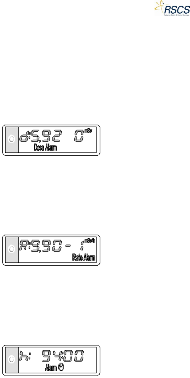
Figure 15 Simulated "Time" Alarm Threshold Display
Figure 15 illustrates the display that corresponds to a time alarm threshold of 94 hours.
REVISION 0 14
DMC 2000TD OPERATORS MANUAL
Figure 16 Simulated "Dose" Pre-Alarm Threshold Display
Figure 16 corresponds to the pre-alarm threshold of the simulated dose equivalent for the main
measurement, shown above as 1 mSv.
Figure 17 Simulated "Rate" Pre-Alarm Threshold Display
The value shown in Figure 17 corresponds to the pre-alarm threshold of the simulated dose equivalent
rate for the main measurement (shown here as 0.130 mSv/h).
Switching to Pause Mode
Switching to Pause Mode primarily consists of deactivating the Active Mode. Once in Pause Mode, the
DMC 2000TD remains capable of receiving commands from the SCC application.
Note: Unlike the DMC 2000S, the DMC 2000TD is not truly “off” unless it displays “*Off*”.
To enter Pause Mode from Active Mode using the SCC application:
• From the Control Page Select the DMC 2000TD(s) to be entered to Pause Mode by ensuring they
are highlighted.
• Swipe up from the bottom of the screen and select Pause.
• The DMC 2000TD(s) will enter Pause Mode.
Figure 18 Pause Mode Displays
The DMC 2000TD is capable of displaying a custom message (6 character maximum) in place of “Pause”
as shown above.
Operation in *Off* Mode
When the DMC 2000TD is in “*Off*” mode, it:
• Permanently displays the message “*Off*”or a message indicating a low battery condition
illustrated in Figure 19.
15 REVISION 0
DMC 2000TD OPERATORS MANUAL
Figure 19 Low Battery Condition
In this mode the DMC 2000TD uses minimal power consumption. No simulation functions or SCC
connection is available in this configuration.
1.11.3 Operation in Pause Mode
Normal Display
When the DMC 2000TD is in Pause Mode, it continuously performs the operations described in 1.9.5.
The display shows the message “PAUSE” or a user selectable display 6 characters or less (see Figure 18).
In the event of a simulated fault, initiated from the SCC, additional alternating messages are displayed
every two (2) seconds for a two (2) second duration (see example below).
Figure 20 Fault Condition in Pause Mode Display
Note: All dosimeter fault messages are described in 1.13.
Operation of the Selector Button
Using the Selector Button in Satellite Mode allows for:
• Switching the DMC 2000TD from *Off* to Pause Mode
• Displaying the necessary information for the user on the DMC 2000TD’s display
The different functions of the Selector Button are listed below:
Pressing the button:
• Displays the next data
Pressing and holding:
• Maintains the data on the display
After five (5) seconds without pressing:
• Normal display in the Simulated “Pause” Mode
Data Displayed using the Selector Button
Pressing the Selector Button in Pause Mode displays the next data on the display. This information and
the corresponding displays are described hereafter. Depending on the dosimeter’s configuration, some
data can be concealed.
REVISION 0 16
DMC 2000TD OPERATORS MANUAL
Figure 21 DMC 2000TD Display in Pause Mode
Figure 22 DMC 2000TD Display of Operating Mode
The message “Sat” indicates that the DMC 2000TD is configured in “Satellite” Mode.
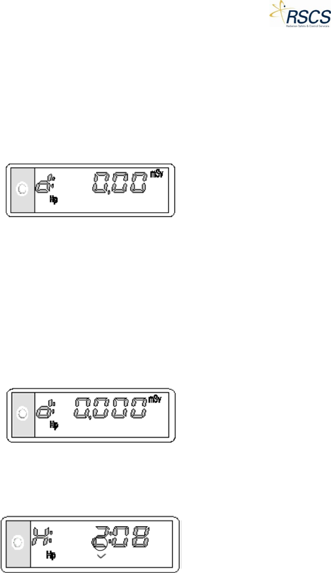
Figure 23 DMC 2000TD Simulated Cumulative Dose Display
The data shown above corresponds to the cumulative dose equivalent for the main measurement during
the last time period in Active Mode (i.e. since the last dose reset to zero). The display is shown in
exponential form. In the example above, the value of the dose corresponds to 5.70 mSv (5.70 x 100
mSv).
Figure 24 DMC 2000TD Simulated Rate Display
This data corresponds to the maximum dose equivalent rate for the main measurement during the last
time period in Active Mode. This display is shown in exponential form. In the example above, the value
of the rate corresponds to 208 mSv/h (2.08 x 10² mSv/h).
Figure 25 DMC 2000TD Simulated Dose Alarm Threshold Display
This data corresponds to the alarm threshold value of the dose equivalent for the main measurement
(shown here 5.92 mSv).
17 REVISION 0
DMC 2000TD OPERATORS MANUAL
Figure 26 DMC 2000TD Simulated Rate Alarm Threshold Display
This data corresponds to the alarm threshold value of the dose equivalent rate for the main
measurement (shown here: 0.990 mSv/h).
Figure 27 DMC 2000TD Simulated Dose Pre-Alarm Threshold Display
This data corresponds to the pre-alarm threshold value of the dose equivalent for the main
measurement (shown here: 1 mSv) if configured.
Figure 28 DMC 2000TD Simulated Rate Pre-Alarm Threshold Display
This data corresponds to the pre-alarm threshold value of the dose equivalent rate for the main
measurement (shown here: 0.130 mSv/h) if configured.
Figure 29 DMC 2000TD Audible Alarm Operating Mode Display
This data corresponds to the function which indicates the ambient rate to the user by an audible signal
which is independent of the display (also known as Chirp Rate):
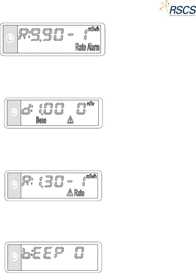
• “BEEP.0” : no audible signal for dose increments
• “BEEP.1” : 1 beep every 10 mrem (100 µSv)
• “BEEP.2” : 1 beep every 1 mrem (10 µSv)
• “BEEP.3” : 1 beep every 0.1 mrem (1 µSv)
• “BEEP.4” : 1 beep every 8 pulses (1 beep/sec/26.7mrem approx.)
• “BEEP.5” : 1 beep every 4 pulses (1 beep/sec/13.3 mrem approx.)
• “BEEP.6” : 1 beep every 1 pulse (1 beep/sec/3.3 mrem approx.)
REVISION 0 18
DMC 2000TD OPERATORS MANUAL
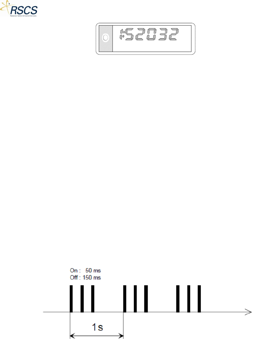
Figure 30 DMC 2000TD Simulated Serial Number Display
This data corresponds to the simulated identification (serial number) written to the DMC 2000TD using
the SCC application.
1.12 Alarms
The DMC 2000TD generates audible and visual alarms when thresholds which have been pre-
determined during configuration are exceeded. In Active Mode these alarm indicators are:
• An audible alarm emitted by the DMC 2000TD buzzer
• A flashing message or symbol on the display
• Three (3) flashes (short flashes by the indicator light) emitted during the alarm, at a rate of 3
quick light flashes per second (if the DMC 2000TD has been configured with this function)
Note:
• In the event of simultaneous alarms, all corresponding messages and symbols are displayed
• The audible alarms and alarm displays can be disabled when configuring the DMC 2000TD; this
function can be configured using the SCC Device Configuration.
1.12.1 Simulated Dose Pre-Alarm
• Cause
o Pre-Alarm threshold for simulated dose equivalent exceeded
o Audible Alarm (see below):
Figure 31 Simulated Dose Pre-Alarm Sound
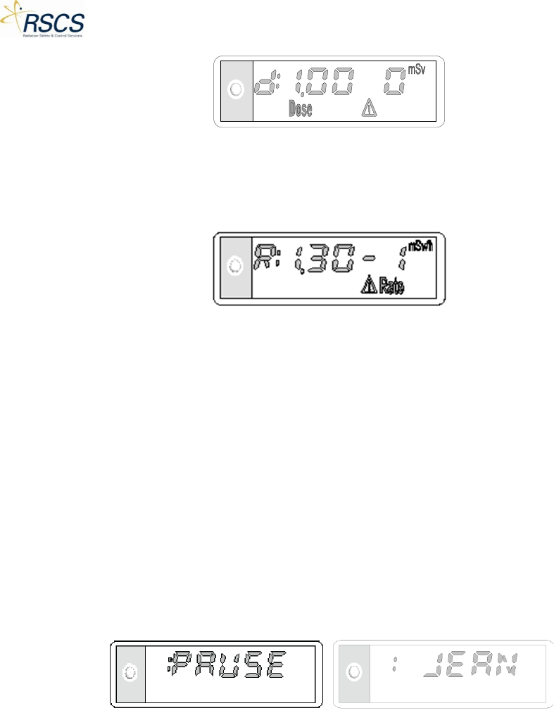
• Display
o The message “Dose” and the “Warning” symbol flash. The dose is still displayed (see
below):
19 REVISION 0
DMC 2000TD OPERATORS MANUAL
Figure 32 Simulated Dose Pre-Alarm Display
• Acknowledgement: this silences the alarm, but does not change the display
o To acknowledge the dose pre-alarm, press and hold the Selector Button for at least
three (3) seconds
Note: In the event a rate pre-alarm occurs at the same time as a dose pre-alarm or a dose alarm, the
audible alarm indication is as follows.
Figure 33 Simulated Dose Pre-Alarm and Rate Pre-Alarm Sound
1.12.2 Simulated Dose Alarm
• Cause
o Simulated dose equivalent alarm threshold exceeded.
o Audible Alarm (see below):
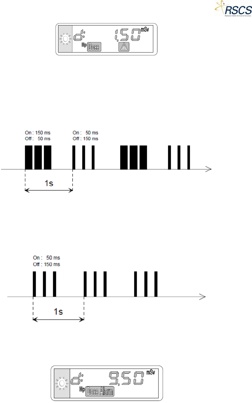
Figure 34 Simulated Dose Alarm Sound
• Display
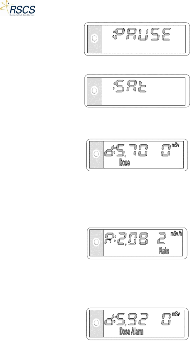
o The message “Dose Alarm” flashes. The dose is still displayed (see below):
Figure 35 Simulated Dose Alarm Display
REVISION 0 20
DMC 2000TD OPERATORS MANUAL
Note: The simulated dose alarm cannot be acknowledged.
1.12.3 Simulated Dose Rate Alarm
• Cause
o Simulated dose equivalent rate alarm threshold exceeded
o Audible Alarm (see below):
Figure 36 Simulated Dose Rate Alarm Sound
• Display
o The message “Rate Alarm” flashes. The dose is still displayed (see below):
Figure 37 Simulated Dose Rate Alarm Display
Note: The simulated dose rate alarm cannot be acknowledged. However, if the simulated dose rate is
set below the threshold again, the alarm will end.
Note: In the event a rate alarm occurs at the same time as a dose pre-alarm or a dose alarm, the audible
alarm indication is as follows.
Figure 38 Simulated Dose Rate Alarm and Dose Alarm Sound
1.12.4 Simulated Duration Alarm
• Cause
o Alarm threshold exceeded
Note: The time alarm can only be set using the SCC Device Configuration.
21 REVISION 0
DMC 2000TD OPERATORS MANUAL
• Audible Alarm one beep every second
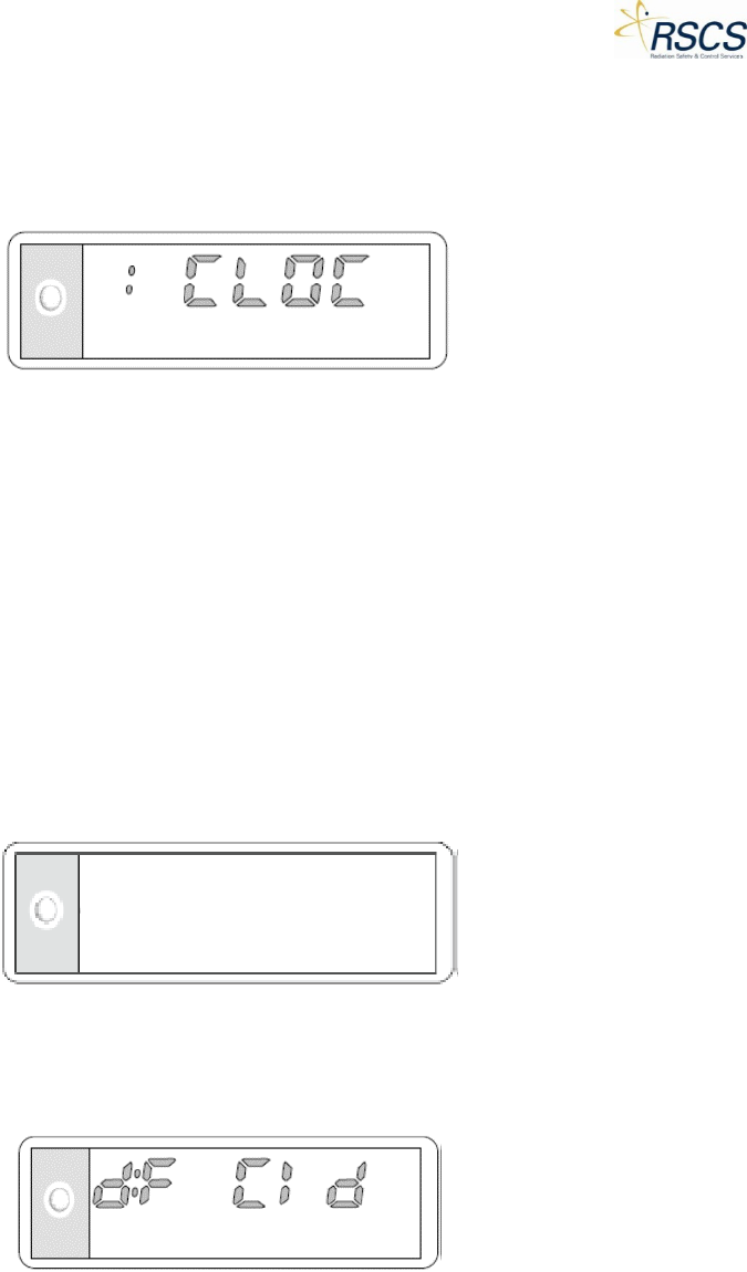
• Display
o The message “CLOC” and the simulated measurement alternate on the display (see
below):
Figure 39 Simulated Duration Alarm Display
1.13 Simulated Faults
This section explains the User Selectable Simulated Faults (also called Alarms in SCC) on the DMC
2000TD. Using the SCC application, each of the following faults may be selected individually. Each fault is
meant to simulate an actual fault on a real DMC 2000S dosimeter. These faults are indicated by one or
both of the following:
• An audible signal emitted by the DMC 2000TD buzzer
• Display of the current Fault message on the DMC 2000TD display
Simulated Faults can be activated from the Control Page. See section 2.3.4.
1.13.1 Blank Screen
When selected the DMC 2000TD display will go blank (see below):
Figure 40 Simulated Blank Screen Fault
1.13.2 Integrated Circuit Fault
When selected the DMC 2000TD will display “dF Cld” (see below):
Figure 41 Simulated Integrated Circuit Fault Display
The simulated fault (“dF Cld”) is meant to replicate an actual DMC fault in the component used for the
nuclear pulse count.
1.13.3 Initialization Fault
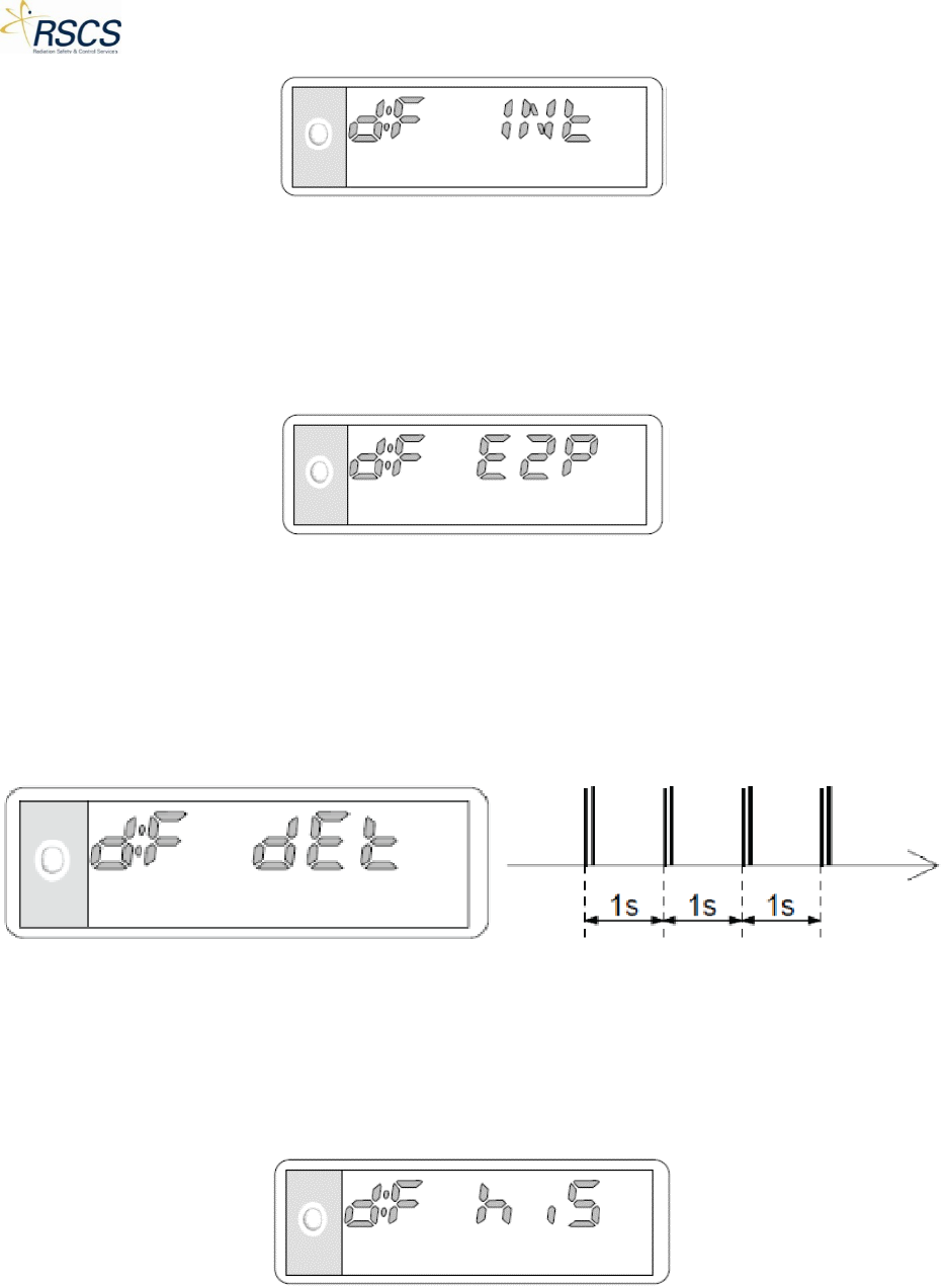
When selected, the DMC 2000TD will display “dF INt” (see below):
REVISION 0 22
DMC 2000TD OPERATORS MANUAL
Figure 42 Simulated Initialization Fault Display
The simulated fault (“dF INt”) is meant to replicate an actual DMC fault where there is a data integrity
problem.
1.13.4 E2PROM Fault
When selected, the DMC 2000TD will display “dF E2P” (see below):
Figure 43 Simulated E2PROM Fault Display
The simulated fault (dF E2P”) is meant to replicate an actual DMC fault where there is a problem
accessing data saved in E2PROM memory.
1.13.5 Detector Fault
When selected, the DMC 2000TD will display “dF dEt” and have 2 audible pulses every second (see
below):
Figure 44 Simulated Detector Fault Display and Sound
The simulated fault (dF dEt”) is meant to replicate an actual DMC fault where there is a physical, internal
problem related to the DMC’s detection circuit
1.13.6 Historical Fault
When selected, the DMC 2000TD will display “dF his” (see below):
Figure 45 Simulated Historical Fault Display
23 REVISION 0
DMC 2000TD OPERATORS MANUAL
The simulated fault (“dF his”) is meant to replicate an actual DMC fault where there is a problem in the
integrity of the historical data. This would often occur after the battery has been handled (removed or
changed).
1.13.7 Calibration Fault
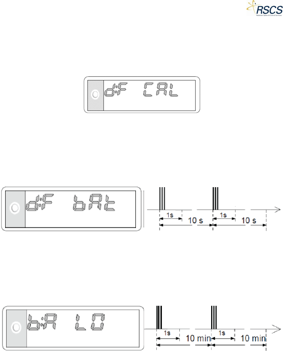
When selected, the DMC 2000TD will display “dF CAL” (see below):
Figure 46 Simulated Calibration Fault Display
The simulated fault (“dF CAL”) is meant to replicate an actual DMC fault where there is a problem in the
integrity of the DMC’s data.
1.13.8 Defective Battery Fault
When selected, the DMC 2000TD will display “dF bAt” and have 3 audible pulses every 10 seconds (see
below):
Figure 47 Simulated Defective Battery Fault Display and Sound
The simulated fault (“dF bAt”) is meant to replicate an actual DMC fault where the battery has been
totally discharged or the battery was removed.
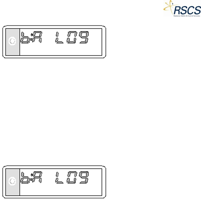
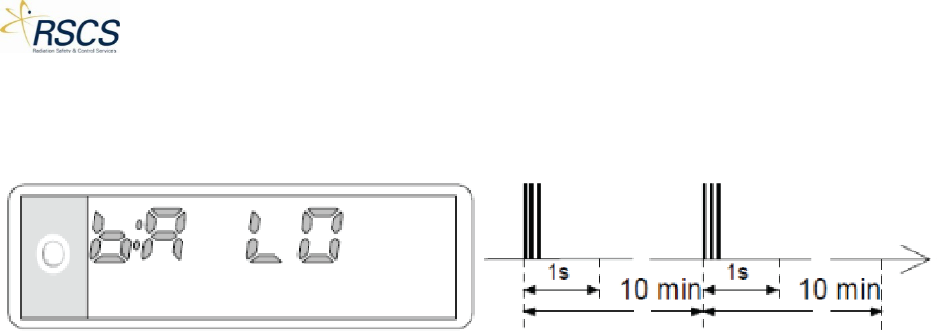
1.13.9 Low Battery Fault
When selected, the DMC 2000TD will display “bA LO” (in Pause Mode) or “bA LO9” (in Active Mode) and
have 3 audible pulses every 10 minutes (see below):
Figure 48 Simulated Low Battery Fault Display and Sound
“bA LO” is displayed in Pause Mode and is meant to replicate an actual DMC fault where there is 72
hours of remaining battery life before the DMC shuts down.
Note: Currently only the “bA LO9” is displayed in measurement mode for simulation purposes. The DMC
2000S will count down the remaining hours of battery life from 9-0.
REVISION 0 24
DMC 2000TD OPERATORS MANUAL
1.14 Non-Simulated Faults
While in Pause or Active Mode, the DMC 2000TD will alert the user of an actual low battery situation. In
this case, the DMC 2000TD will display “*bA LO*” and have 3 audible pulses every 10 minutes.
Figure 49 Battery Low Fault Display
25 REVISION 0

DMC 2000TD OPERATORS MANUAL
1.15 Maintenance
This section describes the maintenance that may be required for the DMC 2000TD. Maintenance is
limited to general cleaning, removing/replacing the DMC 2000TD battery and removing/replacing the
DMC 2000TD clip assembly. Limited maintenance may also be carried out to check the functionality of
the DMC 2000TD.
1.15.1 The DMC 2000TD Battery
If the DMC 2000TD is to be stored for a prolonged period of time the DMC 2000TD battery should be
removed. There is no recommended maximum battery installation period. If there is any uncertainty of
when the DMC 2000TD will be used next the battery should be removed for storage.
1.15.2 Replacement Batteries
Replacement batteries must be suitable for installation into the DMC 2000TD. On no account must
excessive force be used to insert the battery into its compartment. The following are recommended
replacement batteries:
Renata - LiMnO2 / 3V/ CR 2450
Detailed procedures for inserting/replacing the DMC 2000TD battery are given in Section 1.15.1.
1.15.3 Cleaning
The DMC 2000TD is a sealed unit and has protection against dust and low pressure jets of water from all
directions. The unit will not withstand prolonged immersion under pressure. Cleaning should be carried
out if the unit requires general cleaning or if the DMC 2000TD battery has leaked.
1.15.4 General Cleaning
The unit should be cleaned with a damp cloth. Use a neutral water-based detergent, other detergents
may damage or attack the DMC 2000TD outer plastic coating. A small brush should be used to clean any
crevices in the case. After cleaning dry the DMC 2000TD with a soft cloth. During cleaning, water may
enter the alarm sounder aperture. The sounder aperture is watertight, although water ingress may
deaden the alarm. Any water should be shaken or blown out of the sounder aperture to restore the
alarm noise level.
1.15.5 Cleaning after a Battery Leakage
Any leakage of the DMC 2000TD battery must be treated with extreme caution. In most instances
battery leakage will be confined within the DMC 2000TD battery compartment. Minor leakage (light
smearing) may be removed with a cotton swab moistened with a water-based detergent. However, if
doubt exists as to the extent of the leakage the DMC 2000TD should be considered as unusable and
RSCS should be contacted for advice.
1.15.6 Periodic Cleaning
The DMC 2000TD should be cleaned by wiping it over periodically with a cloth lightly dampened with a
solution of water and up to 5% of a neutral water-based detergent.
REVISION 0 26

DMC 2000TD OPERATORS MANUAL
1.16 Shipping and Storage Precautions
There are no special shipping and handling instructions for the DMC 2000TD. However, it is
recommended that the battery be removed prior to shipment and that the unit be placed in a protected
place.
There are no special short term storage requirements for the DMC 2000TD. If the DMC 2000TD is going
to be stored for extended periods of time the battery should be removed prior to placement in storage
(see Section 1.15.1).
27 REVISION 0
DMC 2000TD OPERATORS MANUAL
2 Simulation Control Center
2.1 Introduction
The Simulation Control Center (SCC) is an application written and designed for use with Windows 8.1TM.
SCC can be installed on any Windows 8.1TM Tablet and downloaded for free, directly from the Windows
Store. SCC allows a training instructor to remotely send commands wirelessly to a variety of simulated
radiation detection instruments. This section focuses on the use of SCC with the DMC 2000TD. SCC is
designed for touchscreen use with an intuitive layout for quick and easy control of one or multiple DMC
2000TDs. The Simulation Control Center (SCC) utilizes a USB Dongle containing an IEEE 802.15.4 wireless
module that allows for the individual control of up to thirty-two (32) devices connected at one time.
2.2 Functional Description
2.2.1 General
The Simulation Control Center (SCC) application provides the user a means of wirelessly controlling the
features and functions of a connected DMC 2000TD. The SCC application runs on any Windows 8.1TM
Tablet and communicates wirelessly via a USB Dongle inserted in the Tablet. SCC provides the user with
vital information about any currently connected DMC 2000TDs. It also provides the user a means of
navigating between Training, Control, and Configuration of DMC 2000TDs.
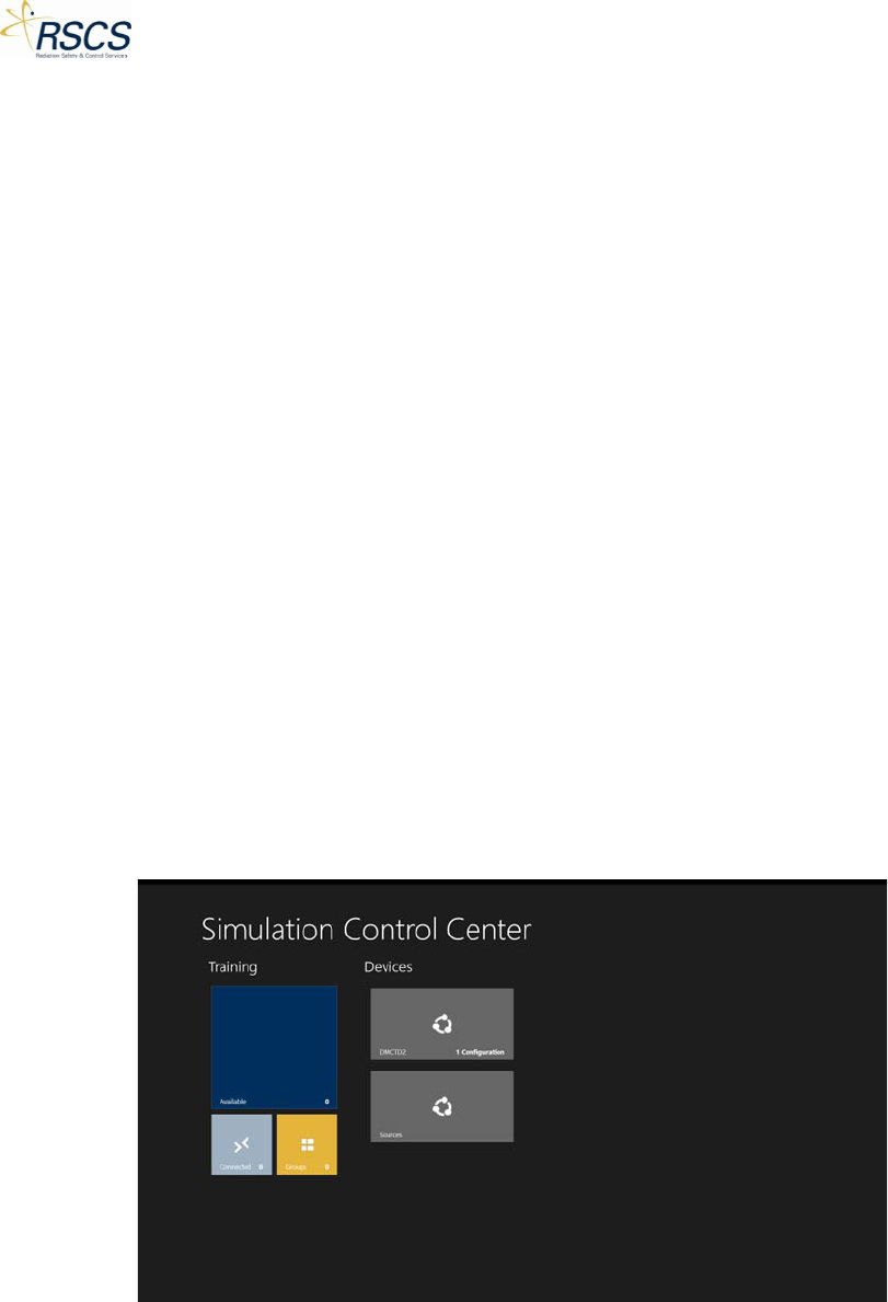
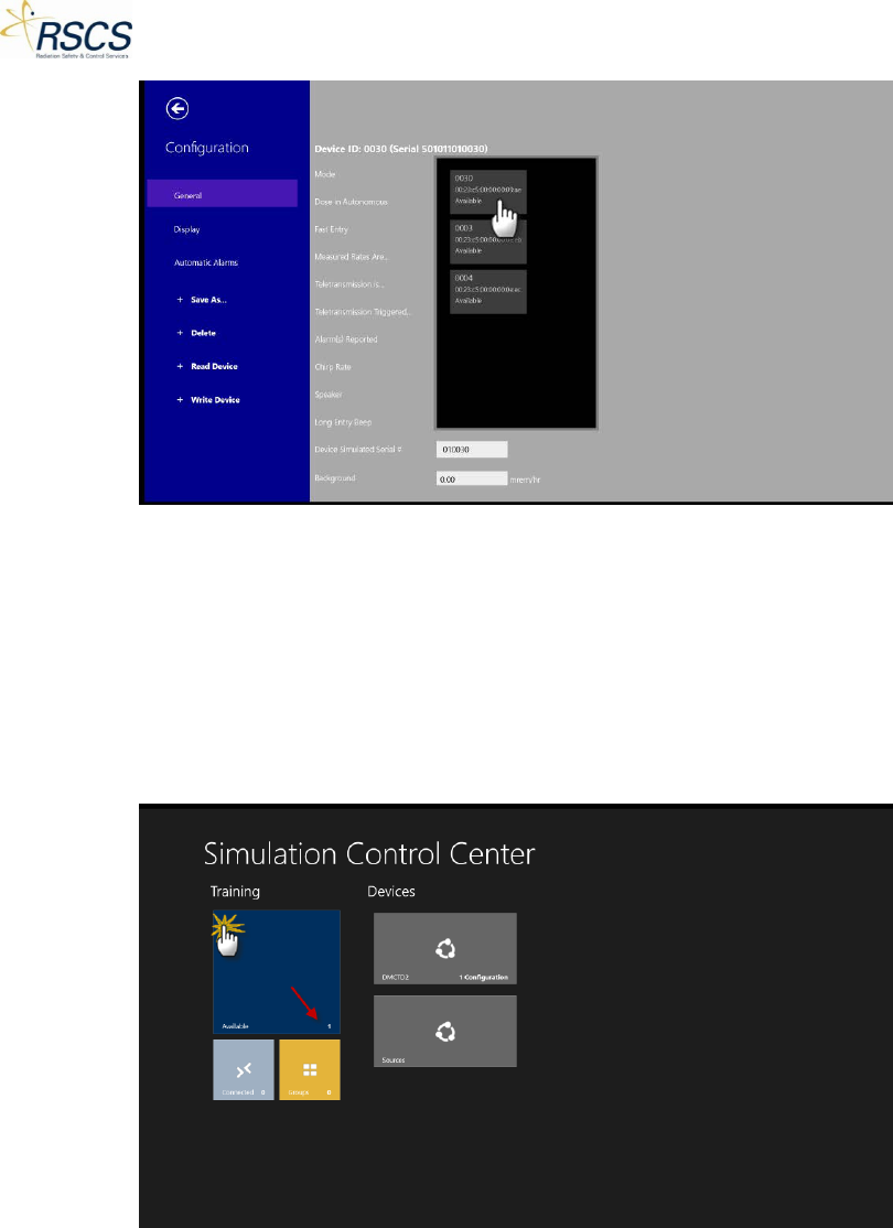
2.2.2 Hub Page
The Hub Page (Figure 50) is the basic interaction point between SCC and DMC 2000TDs awaiting control
or configuration. The Hub Page consists of two main Sections; Training and Device Configuration.
Training allows the user to directly connect with DMC 2000TDs and simulate almost all functions of a
real DMC 2000S dosimeter. Device Configuration allows the user access to the various configurable
options of the DMC 2000TD, similar to Mirion Technologies DosiMass or DMC User software.
Figure 50 SCC Hub Page
2.2.3 Preparations for Use
The Simulation Control Center (SCC) application runs on any Windows 8.1TM Device. SCC comes
preinstalled on the specific Windows 8.1TM Device purchased. Ensure the USB Dongle is installed in the
USB port of the Windows 8.1TM Device.
29 REVISION 0
DMC 2000TD OPERATORS MANUAL
Note: The USB Dongle must be connected to the Device for communication with the DMC 2000TDs.
Once installed, SCC requires no preparation for use other than opening the application.
2.3 Operating Instructions
The following section provides operating instructions for the Simulation Control Center (SCC). These
instructions are specific to the DMC 2000TD only. Specific instructions for other simulator device types
can be found in the device specific section of each manual.
2.3.1 Starting the Simulation Control Center Application
The Simulation Control Center runs as an application on a Windows 8.1TM Device. Ensure the USB Dongle
is properly connected to the Device. Open the SCC application to start using SCC.
2.3.2 Device Configurations
Each DMC 2000TD comes with the same default configuration preloaded during manufacture. It is
recommended to match the DMC 2000TD configuration to the standard site configuration for the real
DMC 2000S dosimeters. Similar to Mirion’s DosiMass or DMC User software, SCC provides a way for the
user to configure specific options related to the DMC 2000TD operation. Prior to use, it is recommended
to verify the configuration settings are applicable to the end user’s needs.
Note: Device Configurations may only be accessed if there are no devices currently in Training Mode.
Opening Device Configurations
To open Device Configurations:
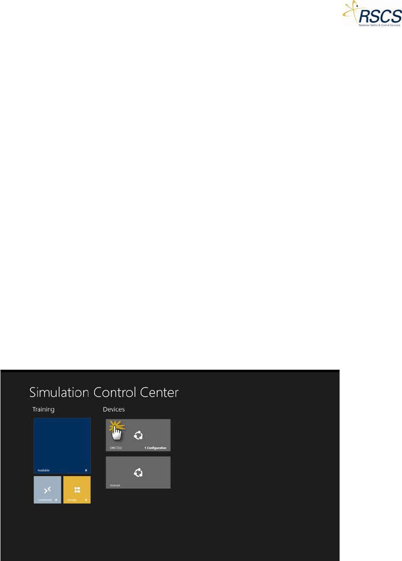
1. From the SCC Hub Page, touch the device configuration Tile under the Devices Section.
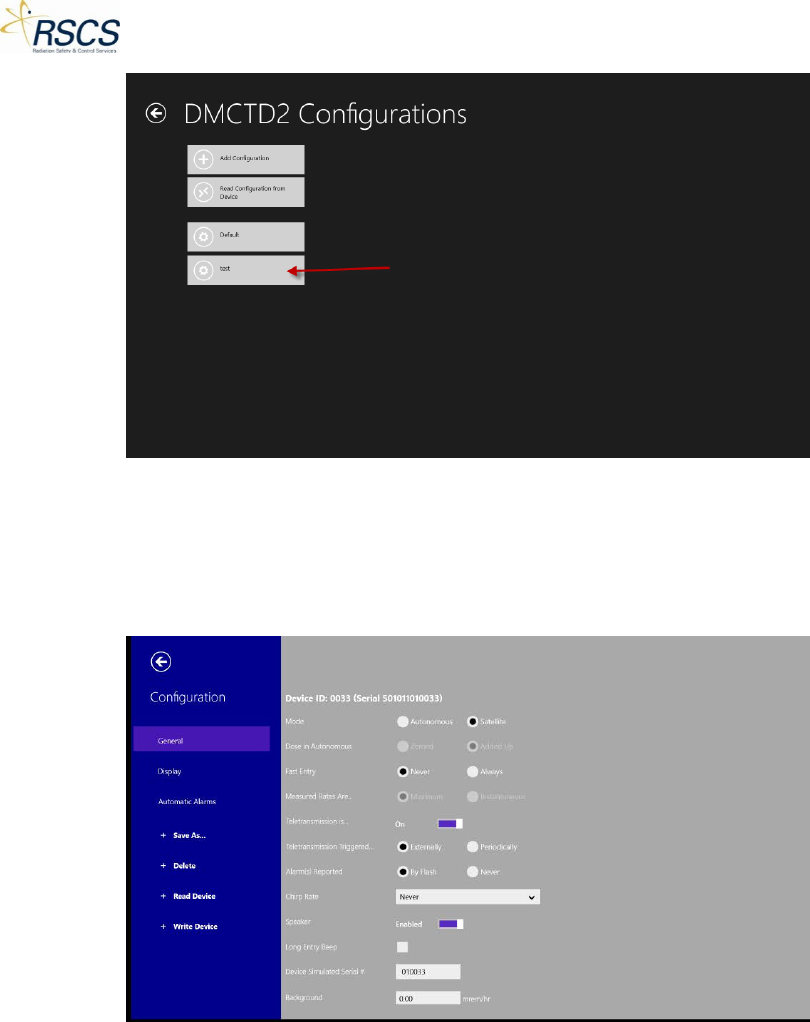
2. The DMCTD2 Configurations Page appears with three (3) options; Add Configuration, Read
Configuration from Device, and Default.
Adding Device Configurations
To add a Configuration specific to site needs, perform the following;
1. Touch Add Configuration.
REVISION 0 30
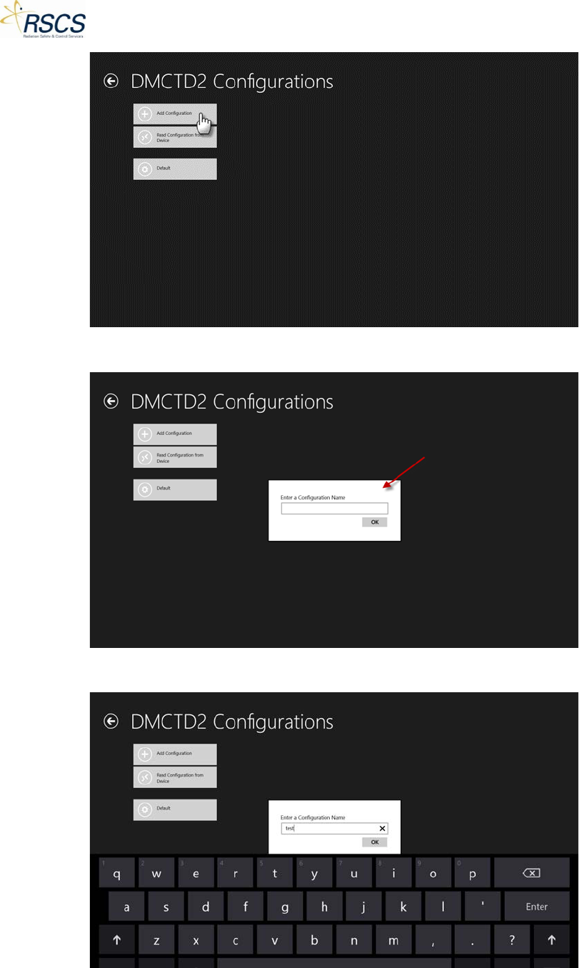
DMC 2000TD OPERATORS MANUAL
2. A pop up box appears for entering a new Configuration name.
3. Type in the desired name and touch OK.
31 REVISION 0
DMC 2000TD OPERATORS MANUAL
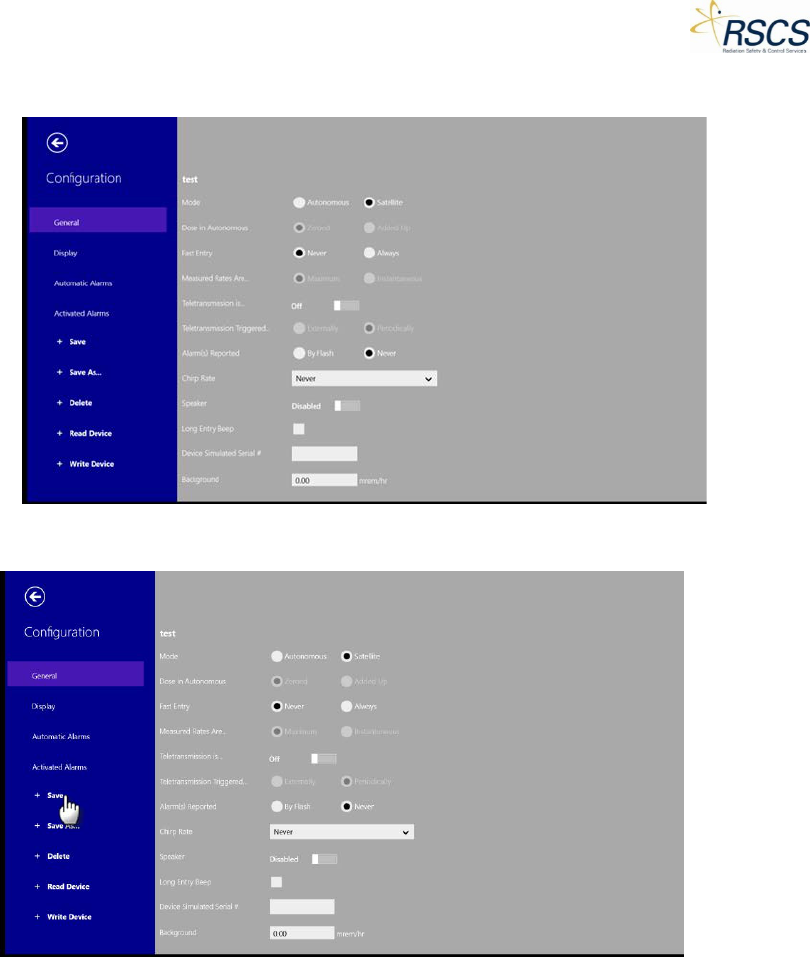
4. The screen switches to the Configuration Options Page.
2.3.2
5. Select the desired options (refer to section 2.3.2) and select Save.
6. The configuration is now saved and added to the DMCTD2 Configurations Page.
REVISION 0 32
DMC 2000TD OPERATORS MANUAL
Default Configuration
To quickly load the Default Configuration that every DMC 2000TD is shipped with, select Default
Configuration and follow the steps in “Read Configuration from Device” to write and save the
configuration to the DMC 2000TD(s) desired. The Default Configuration file contains the following
configuration;
33 REVISION 0
DMC 2000TD OPERATORS MANUAL
Read Configuration from Device
To change or view the configuration of a specific DMC 2000TD, use Read Configuration from Device.
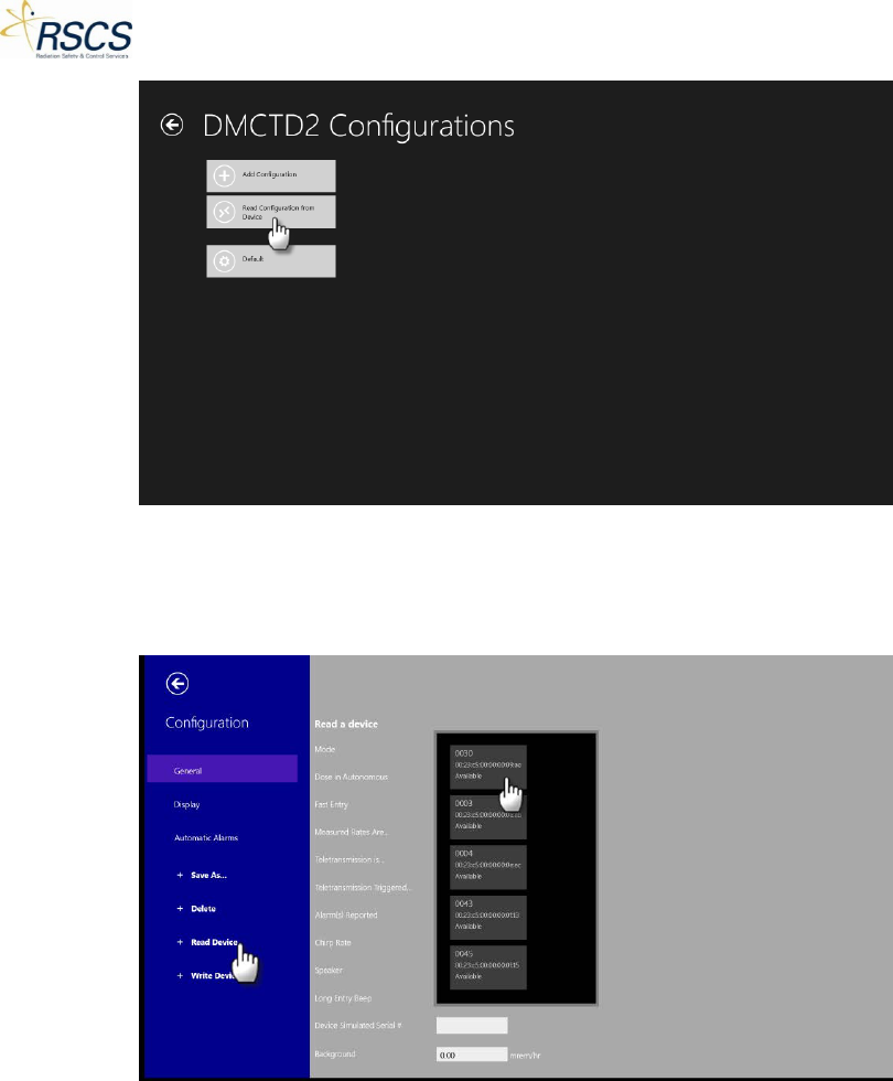
1. Touch the Read Configuration from Device Tile.
REVISION 0 34
DMC 2000TD OPERATORS MANUAL
2. The screen changes to the Configuration options. Select Read Device and select the DMC
2000TD to configure.
Note: Ensure the desired DMC 2000TD is powered on.
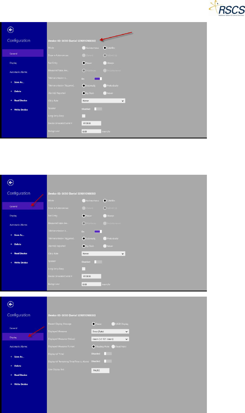
3. The DMC 2000TD configuration will load on the screen populating the Device ID and Device
Serial number. All the options that are selected (or not) are the current configuration of that
DMC 2000TD.
35 REVISION 0
DMC 2000TD OPERATORS MANUAL
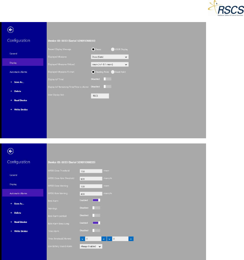
4. Each DMC 2000TD has three (3) pages of configuration options; General, Display, and Automatic
Alarms. These options allow the instructor to more closely match the operation of a DMC
2000TD to the site specific operation of a standard DMC 2000S.
REVISION 0 36
DMC 2000TD OPERATORS MANUAL
Note: All but two configuration options (Device Simulated Serial # and Background found on the General
page) work exactly as a real DMC 2000S. Refer to Mirion Technologies latest DMC 2000S User Manual
for information on each configuration option.
Note: Device Simulated Serial # is a configuration option to match the serial number of a real DMC
2000S dosimeter. Inputting a real DMC 2000S serial number is useful when using Telemetry Monitoring
software such as Teleview 2000 or Teleview 3000.
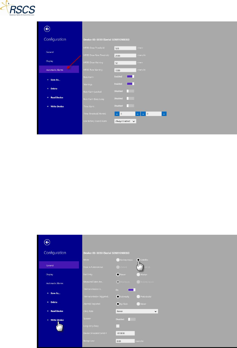
5. To change a configuration option of a DMC 2000TD, select the option desired and touch the
Write Device button.
Note: Ensure the desired DMC 2000TD is powered on.
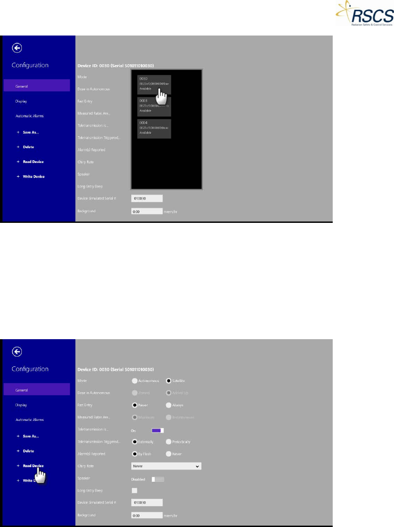
6. A pop up box will appear with a list of available DMC 2000TD’s to write the configuration to.
Select the correct DMC 2000TD by touching the corresponding Tile.
37 REVISION 0
DMC 2000TD OPERATORS MANUAL
7. SCC Configuration will write the new configuration to the selected DMC 2000TD.
Note: After the new configuration is written to the DMC 2000TD, the DMC 2000TD will change Function
Modes to Off Mode. Pressing the Selector Button on the DMC 2000TD will change the Function Mode
back to Pause Mode.
8. To verify the configuration was properly written to the DMC 2000TD, select Read Device and
choose the correct DMC 2000TD from the pop up menu.
REVISION 0 38
DMC 2000TD OPERATORS MANUAL
2.3.3 Connecting to Available DMC 2000TDs
SCC is capable of connecting to any DMC 2000TD currently in Pause Mode or Active Mode and within
range that is not currently connected to another SCC application. To connect to an available DMC
2000TD perform the following actions:
1. Touch the “Available” Tile on the Hub Page to enter the SCC Training Section.
Note: The number of Available DMC 2000TDs will be displayed in the lower right hand corner of the
Available box.
2. SCC switches to the Training Section and shows all available DMC 2000TDs (up to thirty-two
(32)) as unique Tiles.
39 REVISION 0
DMC 2000TD OPERATORS MANUAL
3. Touch the desired DMC 2000TD Tile(s) or press Select All to select all of the available DMC
2000TDs.
Note: The DMC 2000TD Tile(s) will be highlighted with a check in the upper right corner once selected.
Note: Once all the DMC 2000TDs are selected, the Select All option is replaced with Clear All to quickly
unselect the DMC 2000TDs if desired.
REVISION 0 40
DMC 2000TD OPERATORS MANUAL
4. Once the desired DMC 2000TD(s) are selected, touch the Connect button.
Note: Optionally, touching the Control button will bypass the Connect step and go directly to the
Control Page.
41 REVISION 0
DMC 2000TD OPERATORS MANUAL
5. As the DMC 2000TD(s) connect, the unique Tiles will be removed from the Available screen and
move to the Connected Page.
2.3.4 Controlling Connected DMC 2000TDs
From the Connected Page all currently connected DMC 2000TDs are available for Control. To Control a
Connected DMC 2000TD perform the following actions:
Note: It is possible to bypass these steps by touching the Control button instead of the Connect button
in step 1.
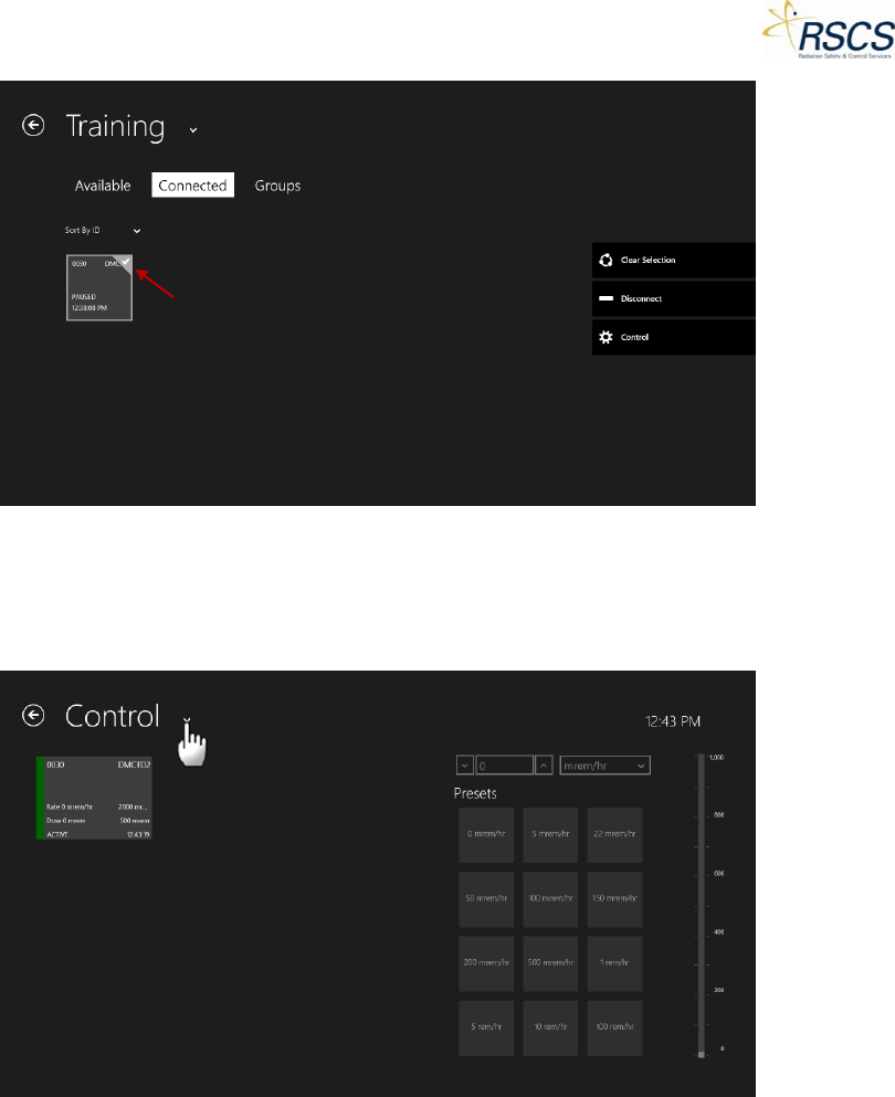
1. Touch the Connected tab to move to the Connected Page.
REVISION 0 42
DMC 2000TD OPERATORS MANUAL
2. Once on the Connected Page, select the desired DMC 2000TD(s) to control by touching the
unique DMC 2000TD Tile(s) or by touching Select All to select all available Connected DMC
2000TDs.
Note: The DMC 2000TD Tile(s) will be highlighted once selected.
43 REVISION 0
DMC 2000TD OPERATORS MANUAL
3. Touch the Control button to begin controlling the selected DMC 2000TD(s).
4. The screen will switch from the Training Section to the Control Page.
REVISION 0 44
DMC 2000TD OPERATORS MANUAL
Control Page
The Simulated Control Center (SCC) Control Page provides access to all the Active Mode control options
of the DMC 2000TDs. The trainer also has access to switch any controlled DMC 2000TD between the
three function modes (Active, Pause, and Off). From the Control Page the trainer can activate any
controlled DMC 2000TD separately or as a group.
SCC Control Page Layout
The SCC Control Page is comprised of four (4) sections; SCC Screen Options, Device List, Dose Rate
Control Options, and the App Bar. Each section controls a specific function of SCC or the DMC 2000TD(s).
Interacting with the SCC Control Page
On the Control Page, the SCC Screen options allow the instructor to quickly switch between SCC screens.
The instructor can switch with a simple back button push or by using the drop down option list of all SCC
Sections and Pages.
Using the Back Button
From the Control Page, touching the Back Button in the upper left hand corner will take the instructor
from the Control Page to the Connected Page.
45 REVISION 0
DMC 2000TD OPERATORS MANUAL
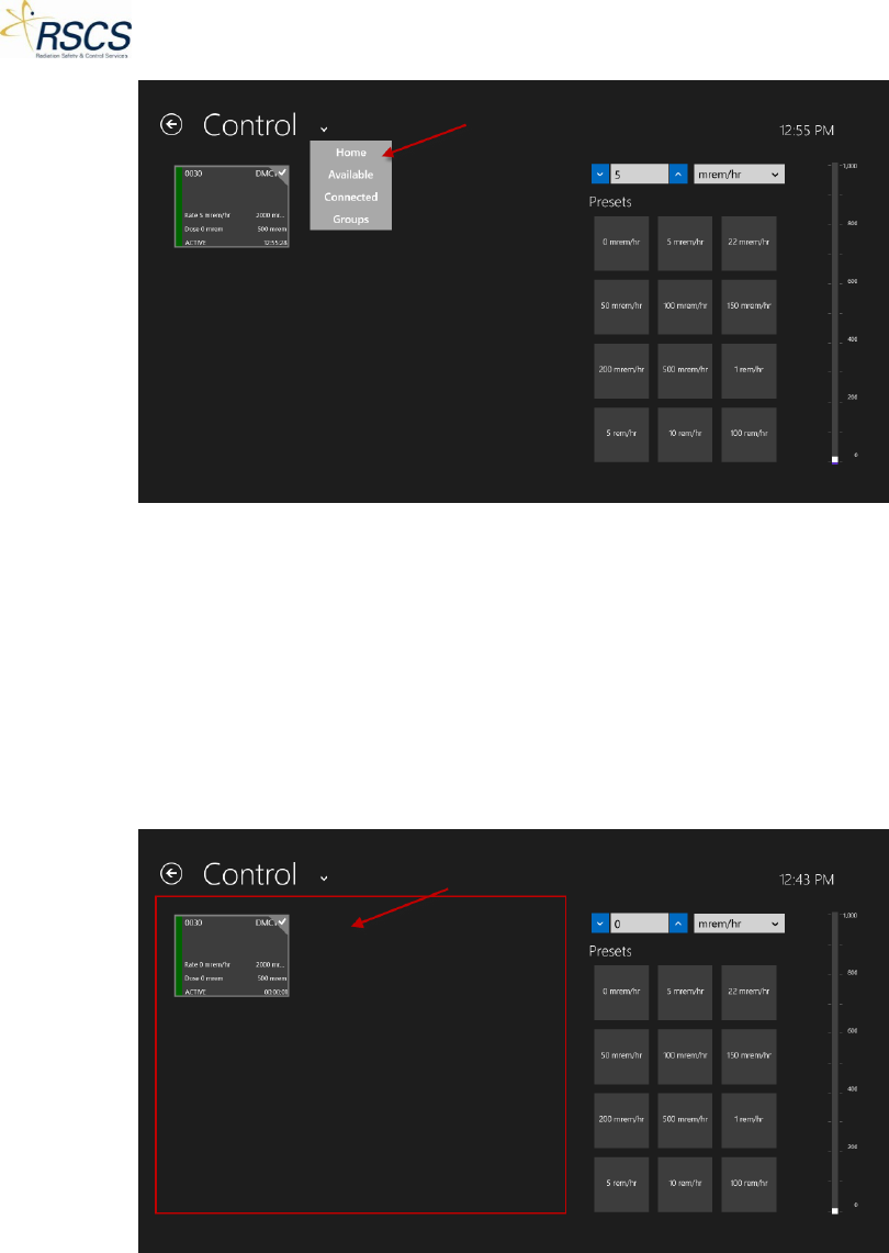
Using the Drop Down Option List
From the Control Page, touching the drop down arrow next to Control will display a list of screen
options. The instructor may choose any of the following Sections or Pages; Home, Available, Connected,
and Groups.
REVISION 0 46
DMC 2000TD OPERATORS MANUAL
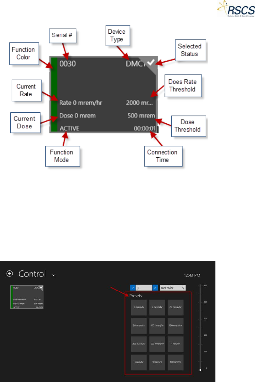
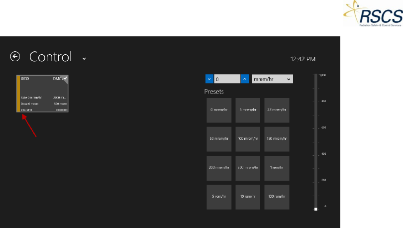
Device List
On the Control Page, the Device List populates with all connected DMC 2000TDs. Each DMC 2000TD will
appear in Tile form with the following information; Serial number, Device Type, Assigned name (if
assigned), Current Dose and Dose Rate, Dose and Dose Rate Thresholds, current Function Mode, color
coded Function Bar, and last time of communication.
Note: The option exists for List View of the DMC 2000TDs. List View is discussed in the App Bar specific
section later on in this Chapter.
Note: The Color Coded Function Bar turns Green for Active Mode and Yellow for Pause Mode.
47 REVISION 0
DMC 2000TD OPERATORS MANUAL
Dose Rate Control Options
On the Control Page, the right hand side of the screen is specifically for simulated Dose Rate control of
the DMC 2000TD(s). Three (3) options are available for controlling the simulated dose rate of the DMC
2000TD(s); Presets, Direct Number Input, and a Slide Scale.
Presets
Twelve (12) default preset dose rates are built-in to SCC. For any Active DMC 2000TD currently in
control, the preset dose rates can be sent to the DMC 2000TD by touching the preset Tile. Additional
presets can be added using the App Bar.
Direct Number Input
To directly input a specific dose rate, the instructor can touch on the number field and directly input a
dose rate via the keypad pop-up. Alternatively, pressing the up or down arrows on the side of the
REVISION 0 48
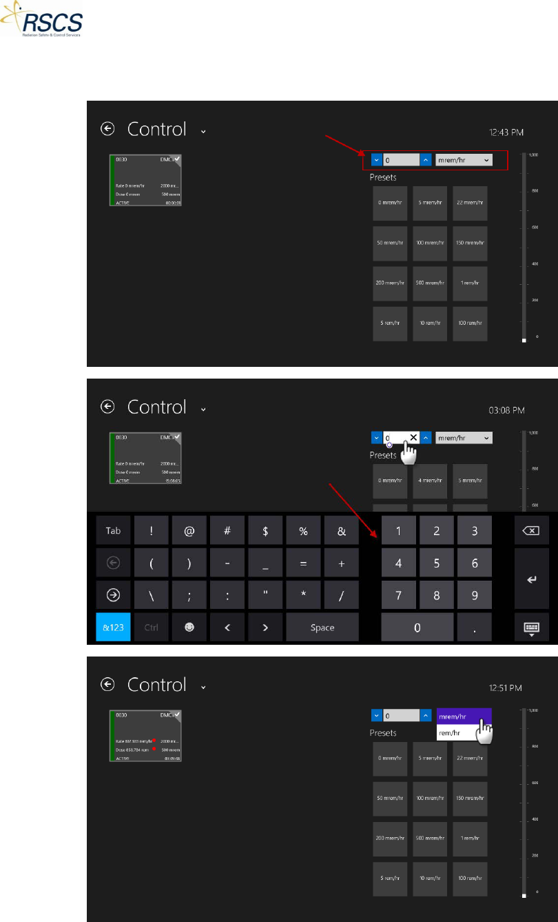
DMC 2000TD OPERATORS MANUAL
number field will adjust the number by one. Touching the dose rate units drop down will allow greater
step changes (i.e. mrem/hr and rem/hr).
49 REVISION 0
DMC 2000TD OPERATORS MANUAL
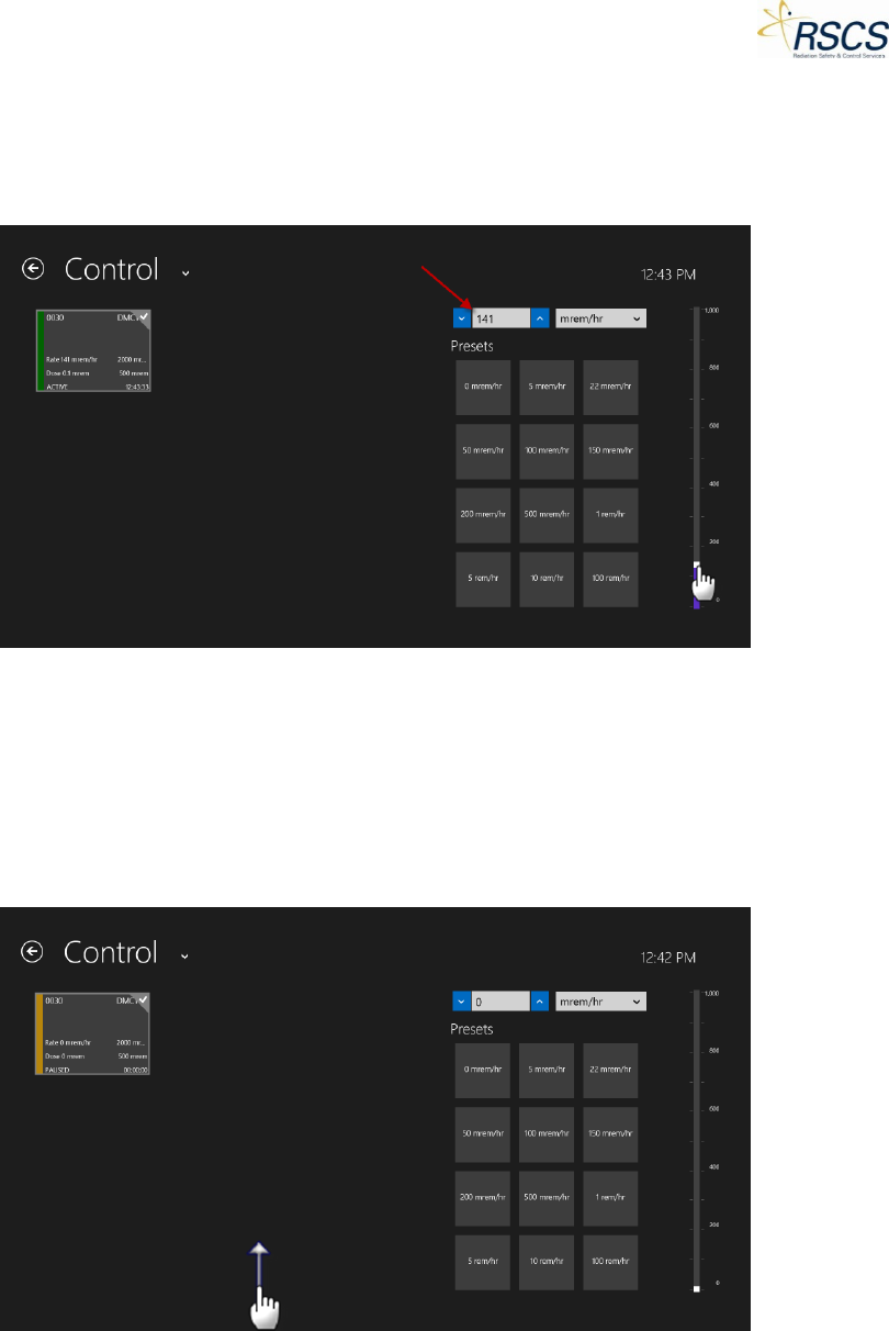
Slide Scale
To quickly adjust the DMC 2000TD(s) simulated dose rate, the instructor can slide the scale on the right
hand side of the Control Page. This allows for very quick adjustment up and down. The slide scale
directly correlates to the direct number input and vice versa.
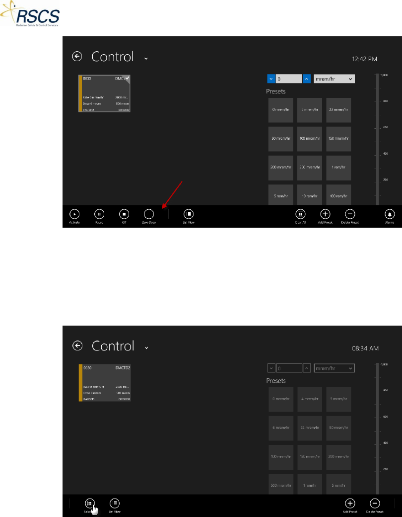
App Bar
The App Bar contains options for both Selected and Unselected DMC 2000TDs. For Unselected DMC
2000TDs it contains four (4) functions; Select All, List View, Add Preset and Delete Preset. For Selected
DMC 2000TDs it contains six (6) major functions; Function Mode Adjustment, Zero Dose, List View, Clear
All, ±Presets, and Alarms. The App Bar is hidden until the instructor swipes up from the bottom of the
screen. The App Bar hides again after all functions except for ±Presets and Alarms. To dismiss the App
Bar or On-Screen keyboard touch anywhere else on the screen.
REVISION 0 50
DMC 2000TD OPERATORS MANUAL
Unselected DMC 2000TDs:
Select All
When no DMC 2000TDs are selected, the instructor can either touch each DMC 2000TD Tile individually,
or use the Select All feature to select all connected DMC 2000TDs in the Device List.
To use Select All, touch the Select All button and all DMC 2000TDs in the Device List will be selected.
51 REVISION 0
DMC 2000TD OPERATORS MANUAL
List View
List View provides the instructor the option of viewing all DMC 2000TDs in the Device List in a list form,
rather than a Tile form. This option is useful for viewing a large number of DMC 2000TDs at one time.
List View has the same function with Selected and Unselected DMC 2000TDs. See number three (3) of
Selected DMC 2000TDS for more information on List View.
±Presets
The Add and Delete Preset buttons are the same for Selected and Unselected DMC 2000TDs. See
number five (5) of Selected DMC 2000TDs for more information on adding and deleting Presets.
Selected DMC 2000TDs:
Function Mode Adjustment
All Connected adjustments of the DMC 2000TD Function Modes are found on the App Bar. To change
the Function Mode of a DMC 2000TD see “App Bar”.
Zero Dose
Zero Dose is used to quickly return a DMC 2000TD to zero (0) accumulated dose. This option avoids
having to place a DMC 2000TD in Pause to clear the accumulated dose. Zero Dose is an option most
useful for an instructor to remove a Dose Alarm from a DMC 2000TD without having to change the
Function Mode.
To use Zero Dose, touch the Zero Dose button and a pop up will appear asking to confirm the action. If
confirmed, any selected DMC 2000TD(s) will clear all accumulated dose.
Note: If a simulated dose rate is above zero when the Zero Dose option is selected, dose will continue to
accumulate starting from zero (0).
REVISION 0 52
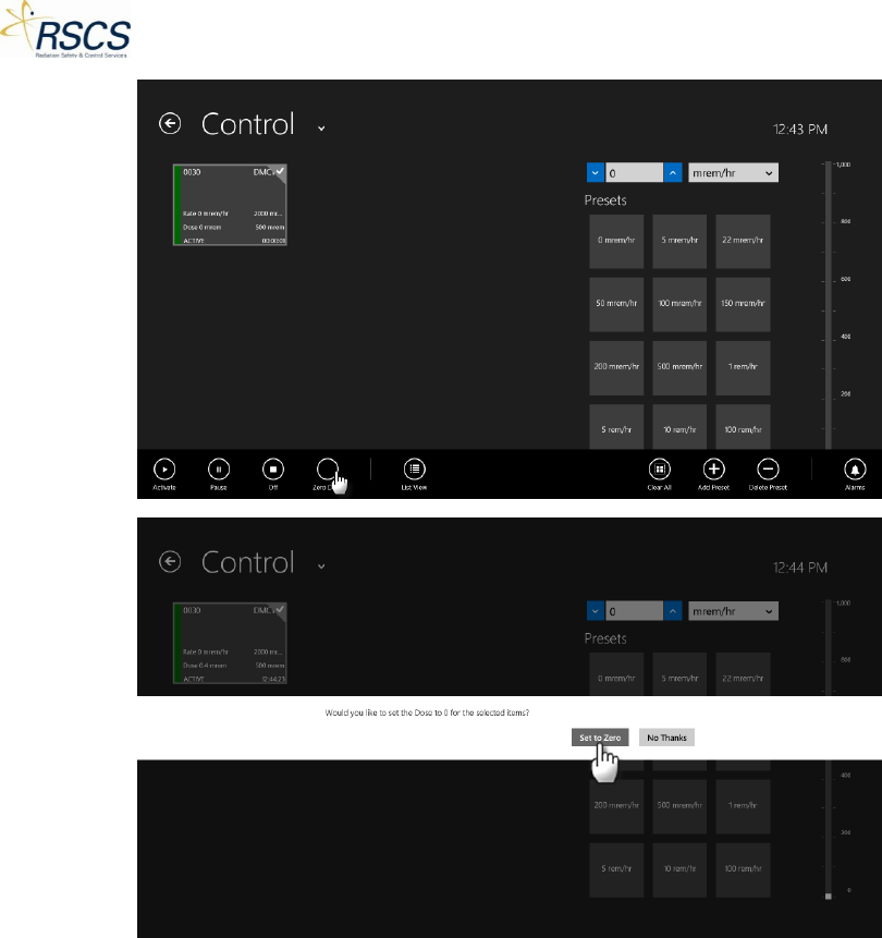
DMC 2000TD OPERATORS MANUAL
List View
List View provides the instructor the option of viewing all DMC 2000TDs in the Device List in a list form,
rather than a Tile form. This option is useful for viewing a large number of DMC 2000TDs at one time.
To use List View, touch the List View button and the Device List will change to a list view style. To change
back to Tile View, swipe up to reveal the App Bar and touch the Tile View button.
Note: When the Device List is displayed as List View, the List View button on the App Bar will change to a
Tile View button.
53 REVISION 0
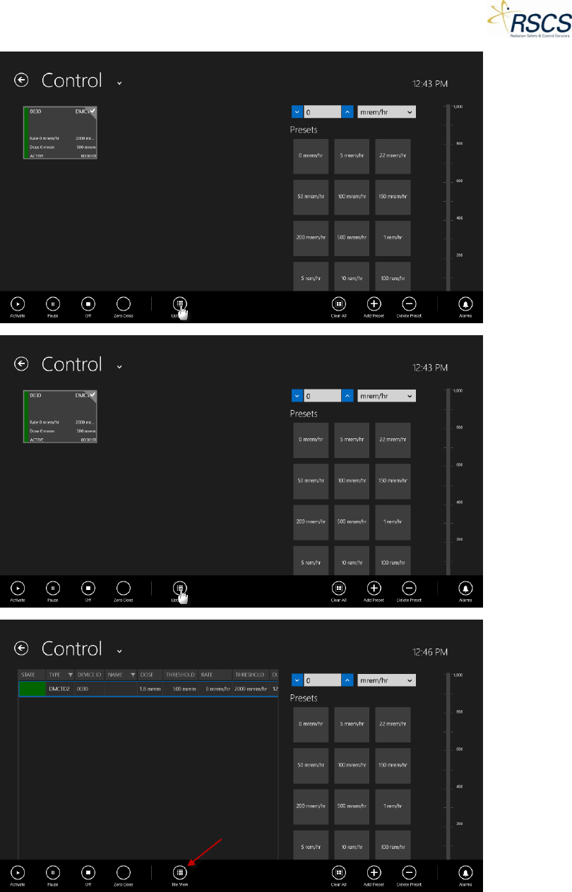
DMC 2000TD OPERATORS MANUAL
Clear All
The Clear All button is used to quickly unselect all DMC 2000TDs that are highlighted in the Device List.
REVISION 0 54
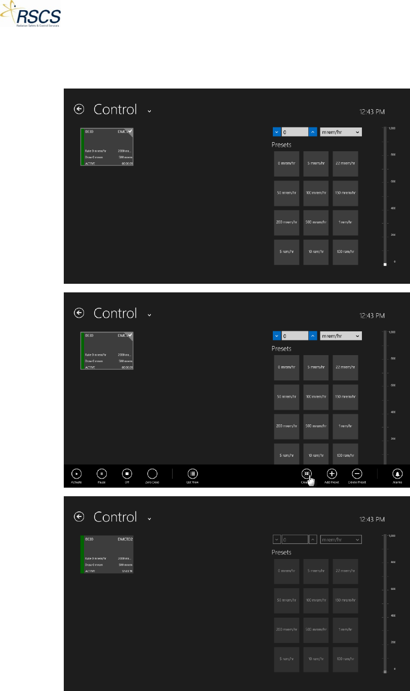
DMC 2000TD OPERATORS MANUAL
Note: Using the Clear All button will remove the ability to control any DMC 2000TD(s) until they are
selected again by touching each Tile or using the Select All button on the App Bar. Also, the Dose Rate
Controls will be grayed out until a DMC 2000TD is selected.
55 REVISION 0
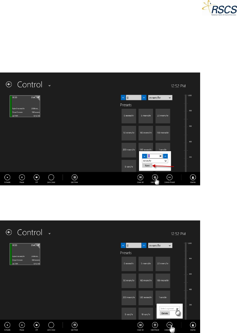
DMC 2000TD OPERATORS MANUAL
±Presets
Two options are available for the Preset Dose Rates; Add Preset and Delete Preset.
To add a preset to the prepopulated list of Presets, use the Add Preset button. Once touched, a pop up
will appear with a direct input box for the dose rate desired and the option to select the units of the
dose rate. Once selected, touch Save and the Preset will be added to the list of Presets for use.
To delete a preset from the list of Presets, use the Delete Preset button. Once touched, a popup will
appear with a drop down list of the available Presets. Touch the drop down list and select the desired
preset. Once selected, touch the Delete button to permanently delete the selected preset.
REVISION 0 56
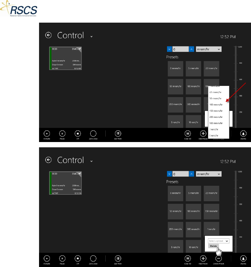
DMC 2000TD OPERATORS MANUAL
Alarms
To enter a DMC 2000TD into a Simulated Fault (see “App Bar”), the instructor must use the Alarms
feature of SCC. Eleven (11) Simulated Faults are available on a DMC 2000TD.
To enter a DMC 2000TD into an Alarm, touch the Alarms button. A popup will appear with a list of
Alarms available for use. Select the desired Alarm by touching the check box next to the alarm. To send
the Simulated Fault to the selected DMC 2000TD(s) touch the Apply button. To remove the Simulated
Fault, uncheck the Alarm and touch Apply.
57 REVISION 0
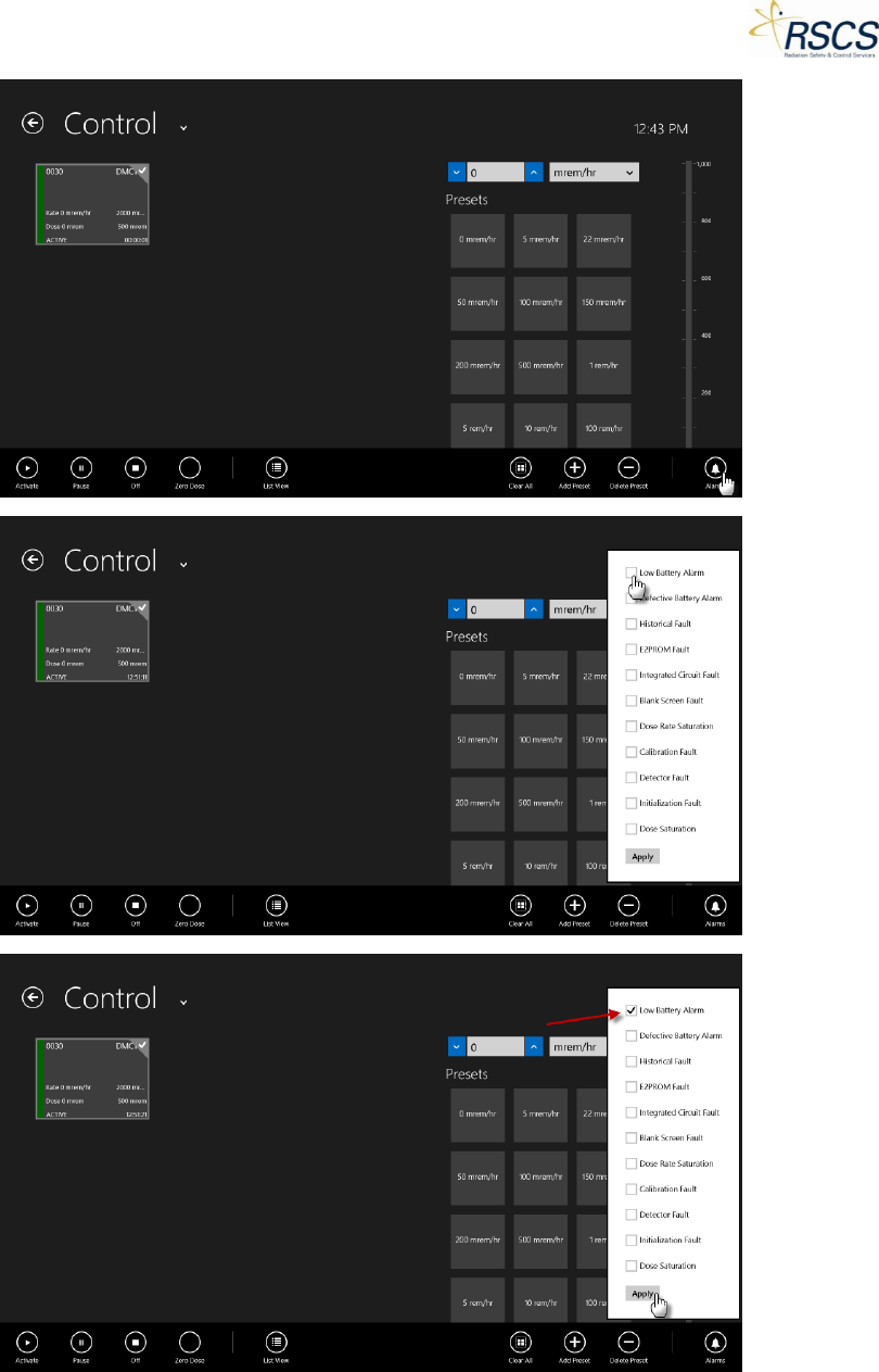
DMC 2000TD OPERATORS MANUAL
REVISION 0 58
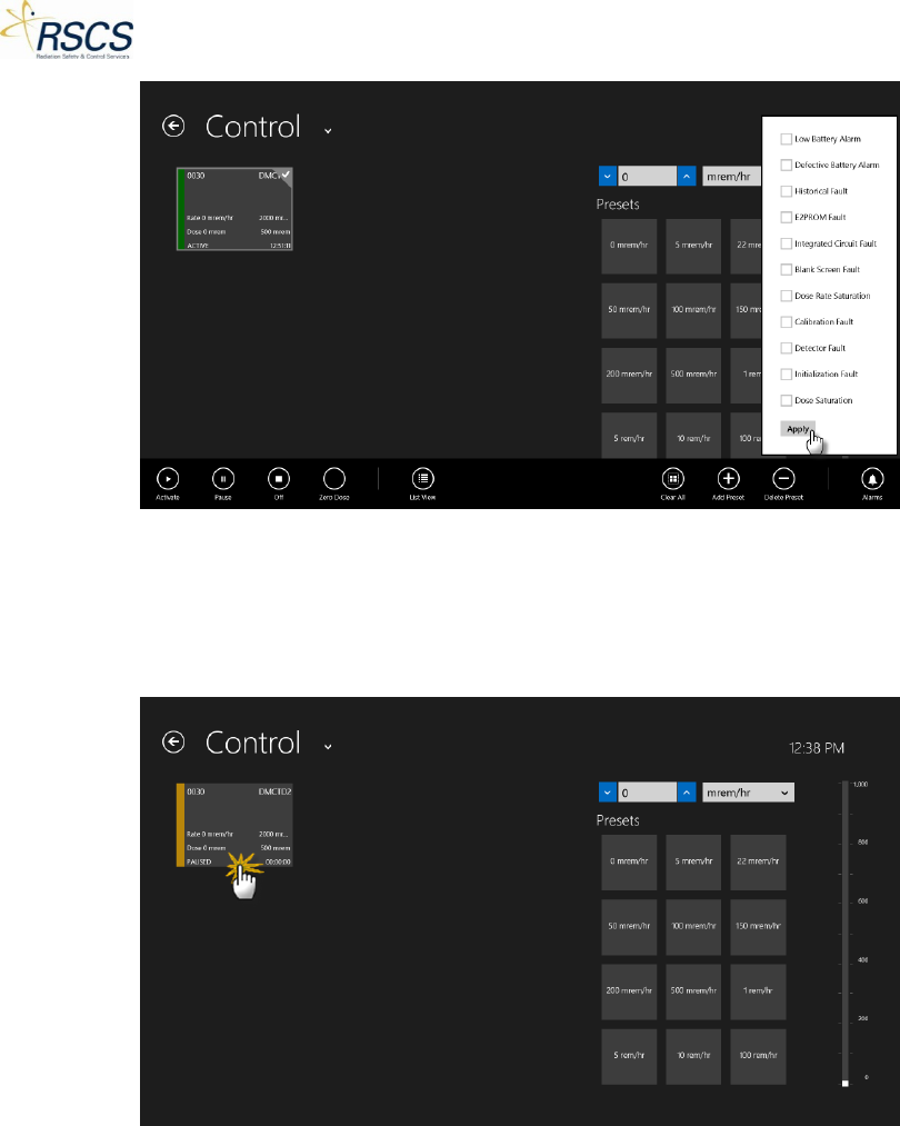
DMC 2000TD OPERATORS MANUAL
Changing DMC 2000TD Function Modes
Changing from Pause to Active Mode
1. From the Control Page, select the desired DMC 2000TDs by touching the unique Tiles.
Note: The DMC 2000TD Tile(s) will be highlighted once selected.
59 REVISION 0
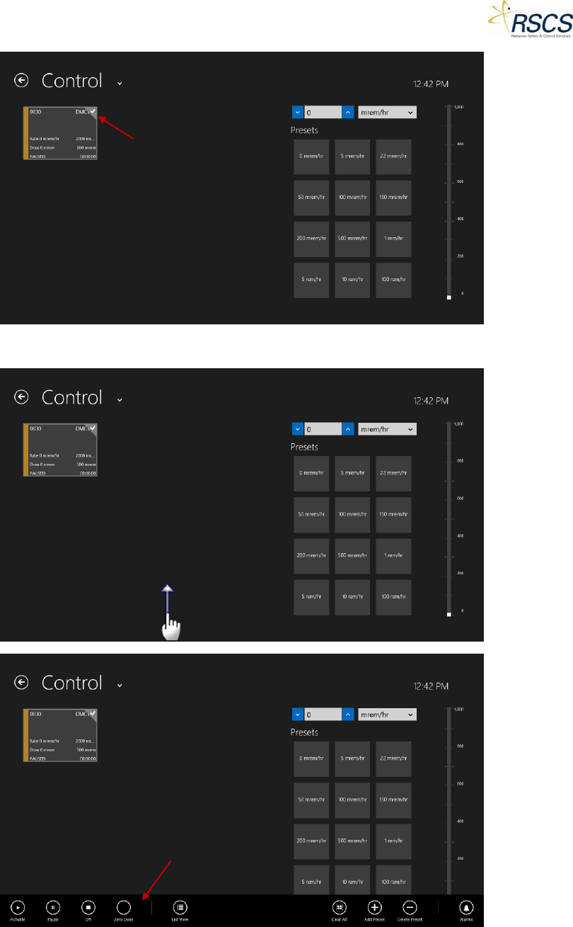
DMC 2000TD OPERATORS MANUAL
2. Swipe up from the bottom of the Control Page to display the App Bar.
3. Touch the Activate button to Activate the DMC 2000TD(s).
REVISION 0 60
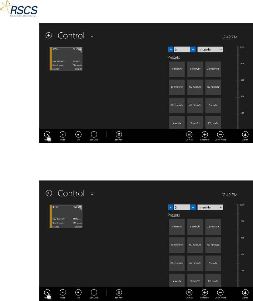
DMC 2000TD OPERATORS MANUAL
4. SCC will wirelessly communicate with the DMC 2000TD(s) and it will switch from Pause Mode to
Active Mode. SCC will change the Tile color from yellow to green and display Active in the lower
left corner of the Tile.
Changing from Active to Pause Mode
1. From the Control Page, ensure the desired DMC 2000TD(s) is highlighted, if not, select the
desired DMC 2000TDs by touching the unique Tiles.
Note: The DMC 2000TD Tile(s) will be highlighted once selected.
61 REVISION 0

DMC 2000TD OPERATORS MANUAL
2. Swipe up from the bottom of the Control Page to display the App Bar.
3. Touch the Pause button to switch the DMC 2000TD(s) to Pause Mode.
REVISION 0 62
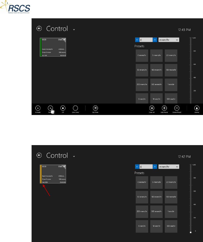
DMC 2000TD OPERATORS MANUAL
4. SCC will wirelessly communicate with the DMC 2000TD(s) and it will switch from Active Mode to
Pause Mode. SCC will change the Tile color from green to yellow and display Pause in the lower
left corner of the Tile.
Changing from Active/Pause to Off Mode
1. From the Control Page, ensure the desired DMC 2000TD(s) is highlighted, if not, select the
desired DMC 2000TD(s) by touching the unique Tiles.
Note: The DMC 2000TD Tile(s) will be highlighted once selected.
63 REVISION 0
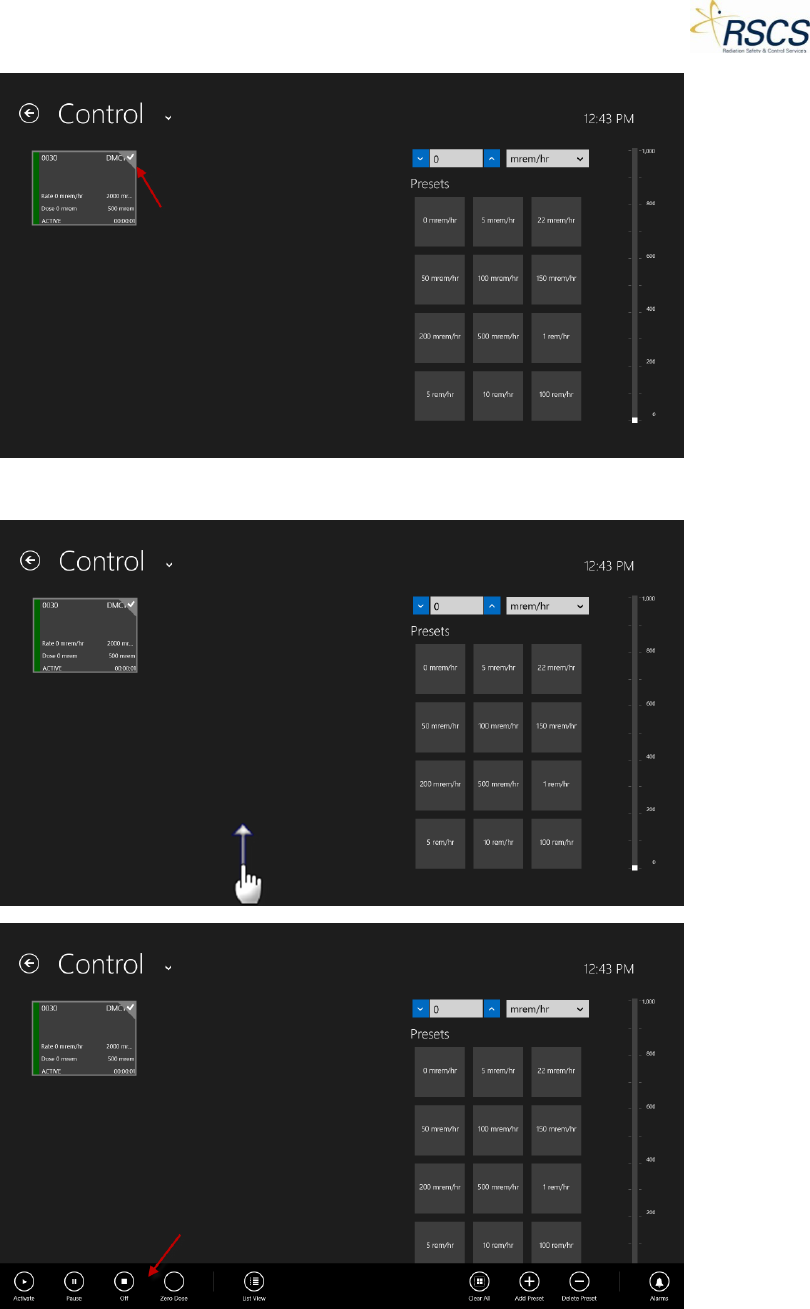
DMC 2000TD OPERATORS MANUAL
2. Swipe up from the bottom of the Control Page to display the App Bar.
3. Touch the Off button to switch the selected DMC 2000TD(s) to Off Mode.
REVISION 0 64
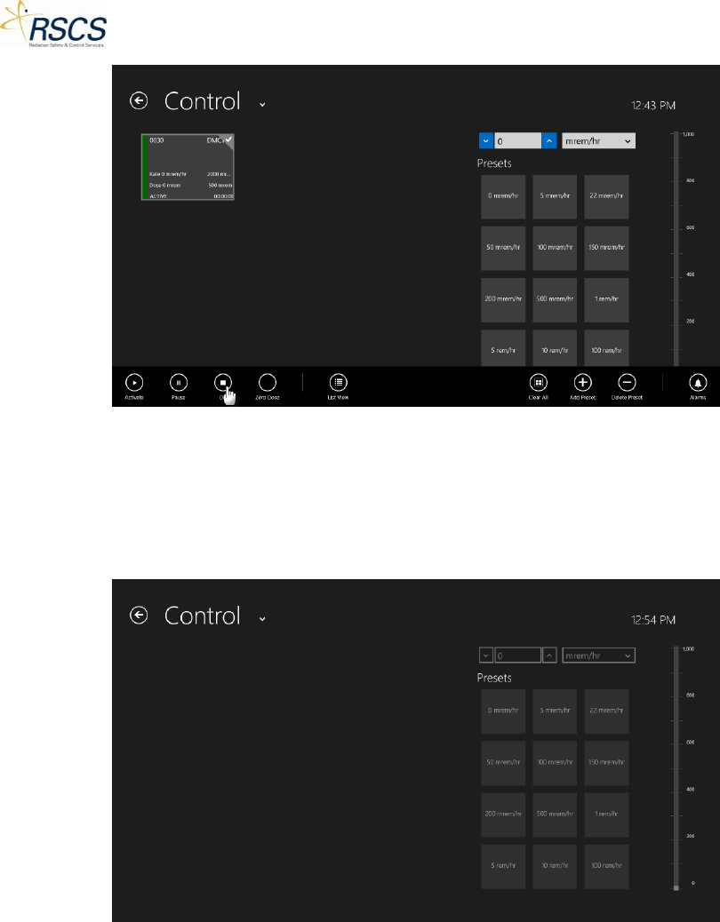
DMC 2000TD OPERATORS MANUAL
4. SCC will wirelessly communicate with the DMC 2000TD(s) and it will switch from Active or Pause
Mode to Off Mode. SCC will no longer show the DMC 2000TD Tile(s) that went to Off Mode. The
Presets and dose rate information will be grayed out.
Note: Once a DMC 2000TD is switched to Off Mode, it can no longer be controlled by SCC and require a
Selector Button push to become available for connection again.
Changing Simulated Dose Rates
One of the main functions of the DMC 2000TD is the ability to simulate dose equivalent rates. This
allows an instructor to train individuals about safe work practices in ever changing environments. The
DMC 2000TD receives a simulated dose rate from the SCC application and remains at that dose rate until
a new command is sent from SCC adjusting the dose rate or Function Mode.
Three (3) options are available for controlling the simulated dose rate of the DMC 2000TD(s); Presets,
Direct Number Input, and a Slide Scale. Refer to “Dose Rate Control Options”.
To change the simulated dose rate of a DMC 2000TD;
1. Ensure the DMC 2000TD(s) is in Active Mode.
65 REVISION 0
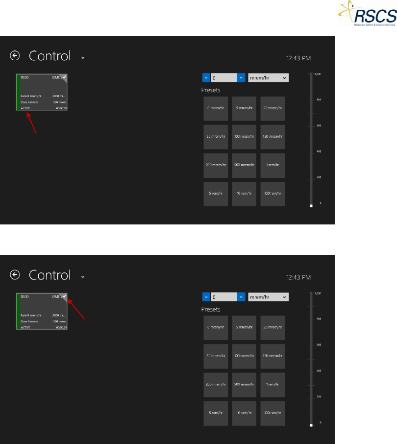
DMC 2000TD OPERATORS MANUAL
2. Select the DMC 2000TD(s) to send a simulated dose rate to.
3. Using one of the three (3) methods of selecting a simulated dose rate value, choose the value to
send (see “Dose Rate Control Options”).
REVISION 0 66
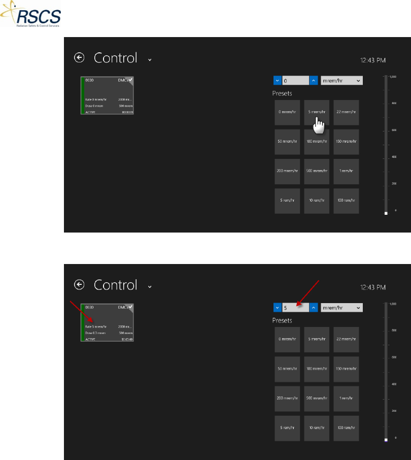
DMC 2000TD OPERATORS MANUAL
4. When the value is selected, SCC will automatically send that value to the DMC 2000TD(s).
5. To adjust the DMC 2000TD(s) to another simulated dose rate value, employ one of the three (3)
options for changing the dose rate value.
67 REVISION 0
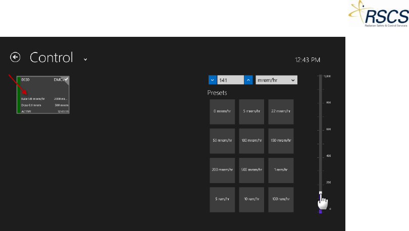
DMC 2000TD OPERATORS MANUAL
6. Returning the simulated dose rate value to zero (0) will stop the DMC 2000TD from continuing
to accumulate dose.
Alarms
During Configuration (see section 2.3.2) each DMC 2000TD is setup with alarm thresholds for the
following categories; Dose Alarm, Dose Rate Alarm, and Time Alarm (if desired). Each of these alarms
has unique characteristics that will trigger the alarm.
Refer to section 1.12 for details on how a DMC 2000TD Hardware Alarm is displayed and the sound
characteristics associated with the alarms on the DMC 2000TD.
Dose Alarm
A Dose Alarm is triggered when a DMC 2000TD has accumulated enough simulated dose to exceed the
preconfigured threshold.
1. Dose Equivalent Pre-Alarm (Warning)
If properly configured, the DMC 2000TD will have a Dose Alarm that acts as a warning to a true Dose
Alarm. With a simple Selector Button push on the DMC 2000TD, the warning alarm will be silenced
however the light will still flash and a warning symbol is shown on the display.
SCC displays a Dose Pre-Alarm warning as a yellow dot next to the Dose Alarm Threshold of the DMC
2000TD Tile.
REVISION 0 68
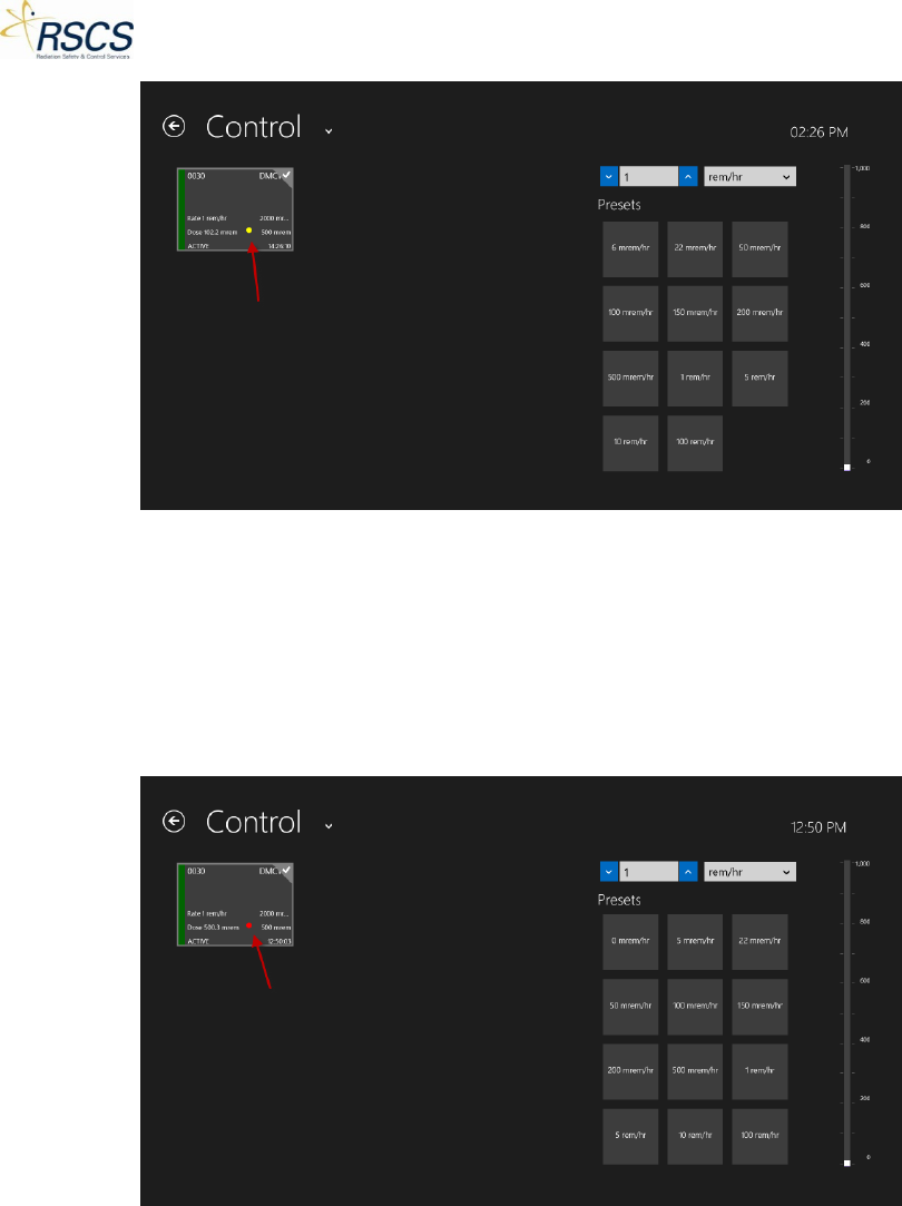
DMC 2000TD OPERATORS MANUAL
2. Dose Equivalent Alarm
The DMC 2000TD will have a Dose Alarm when the accumulated dose exceeds the preconfigured
threshold. This alarm cannot be silenced and will only end when the DMC 2000TD Function Mode is
switched to Pause or Off. Alternatively, using the Zero Dose feature of SCC will end a Dose Alarm (if the
alarm is not set to zero (0)).
SCC displays a Dose Alarm as a red dot next to the Dose Alarm Threshold of the DMC 2000TD Tile.
Note: A combination of Dose and Dose Rate Alarms (and Pre-Alarms) are possible on a DMC 2000TD. In
this scenario, SCC will display a colored dot (depending on alarm type) next to corresponding threshold.
69 REVISION 0
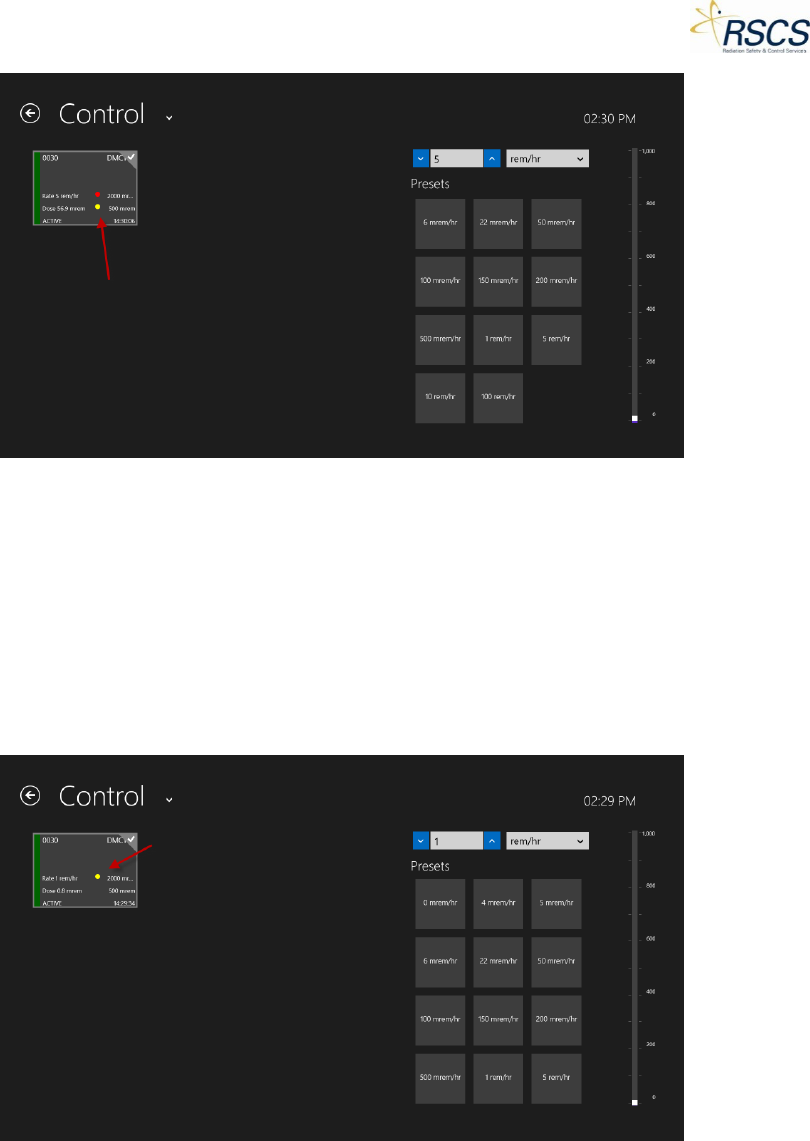
DMC 2000TD OPERATORS MANUAL
Dose Rate Alarm
1. Dose Equivalent Rate Pre-Alarm (Warning)
If properly configured, the DMC 2000TD will have a Dose Rate Alarm that acts as a warning to a true
Dose Rate Alarm. With a simple Selector Button push on the DMC 2000TD, the warning will be silenced
however a warning symbol will still be displayed. If the dose rate is lowered below the Dose Rate Pre-
Alarm threshold, the warning will end.
SCC displays a Dose Rate Pre-Alarm warning as a yellow dot next to the Dose Rate Alarm Threshold of
the DMC 2000TD Tile.
2. Dose Equivalent Rate Alarm
The DMC 2000TD will have a Dose Rate Alarm when the dose rate exceeds the preconfigured threshold.
This alarm will only end when the dose rate is below the threshold again, or the Function Mode of the
DMC 2000TD is switched to Pause or Off Mode.
Note: If a DMC 2000TD is configured for Rate Alarm Latch, a Rate Alarm will not end when the dose rate
goes below the threshold again.
REVISION 0 70
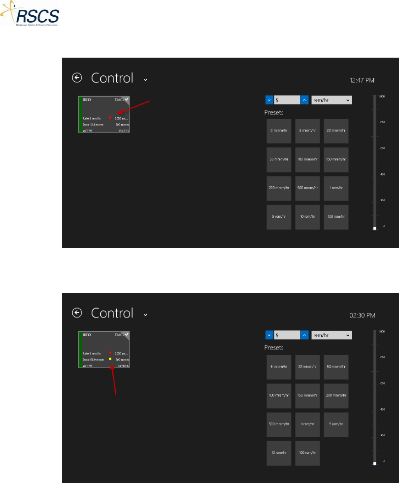
DMC 2000TD OPERATORS MANUAL
SCC displays a Rate Alarm as a red dot next to the Dose Rate Alarm Threshold of the DMC 2000TD Tile.
Note: A combination of Dose and Dose Rate Alarms (and Pre-Alarms) are possible on a DMC 2000TD. In
this scenario, SCC will display a colored dot (depending on alarm type) next to corresponding thresholds.
Time Alarm
If properly configured, a DMC 2000TD can have a Time Duration Alarm or a Time Remaining Alarm.
Neither of these alarms is shown in SCC as they are Hardware Alarms configured directly in the DMC
2000TD and work exactly as a real DMC 2000S Time Alarm.
Simulated Faults and Alarms
Each DMC 2000TD has the ability to simulate eleven (11) Faults or Alarms that a real DMC 2000S could
have in use. These Faults are each described in section 1.13 and work exactly as a real DMC 2000S fault
or alarm.
Each DMC 2000TD is preconfigured with ten (10) of these Alarms that cannot be user configured. The
only configurable alarm is the Low Battery Alarm (see section 2.3.2 Configurations)
71 REVISION 0
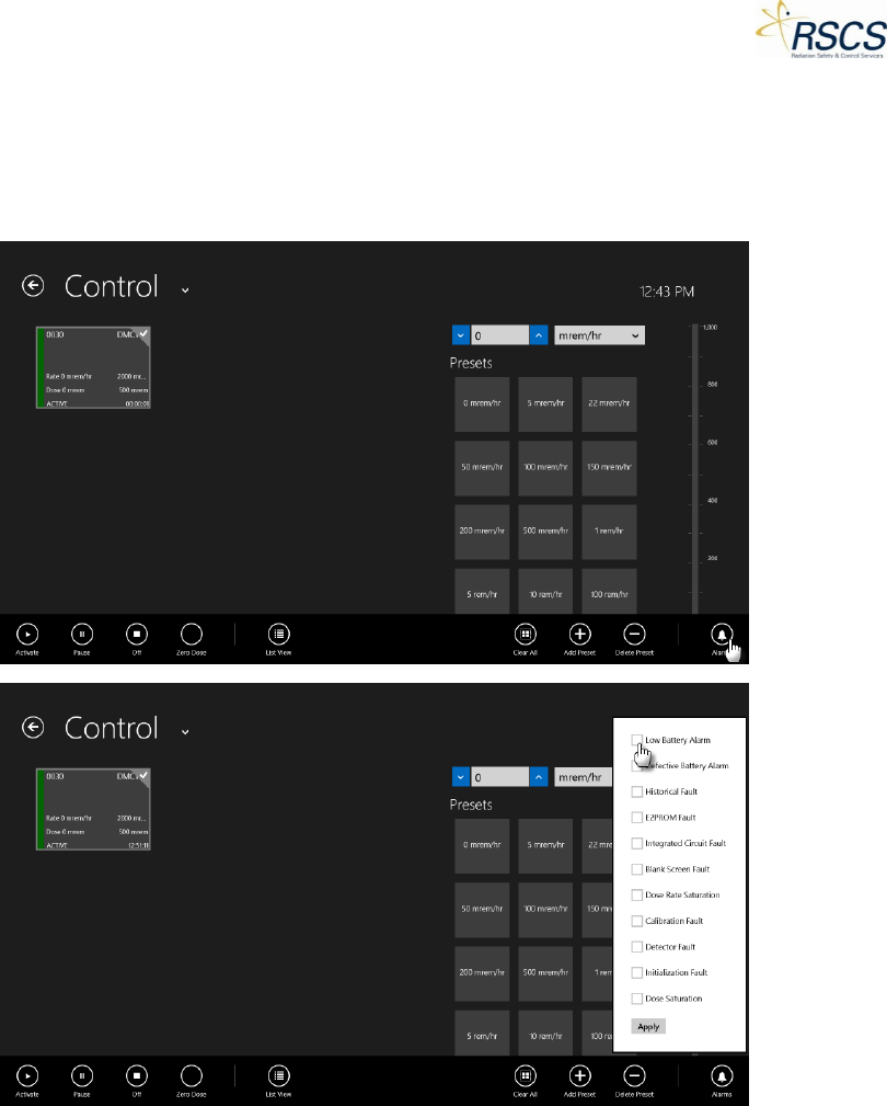
DMC 2000TD OPERATORS MANUAL
All eleven (11) simulated alarms are only activated on the Control Page using the App Bar Alarms
feature.
Note: Each DMC 2000TD has the ability to display a Low Battery Alarm (*BaLo*) upon actual low battery
voltage.
Autonomous Mode
Each DMC 2000TD has the ability work in Autonomous Mode like a real DMC 2000S. Autonomous Mode
is set in Configurations (see section 2.3.2) A DMC 2000TD configured for Autonomous Mode will
maintain the same functionality as a DMC 2000TD in Satellite Mode except for the option to control
some Function Modes with the Selector Button.
In Autonomous Mode, a DMC 2000TD is capable of switching from Pause Mode to Active Mode using
the Selector Button. It is also capable of switching from Active Mode to Pause Mode with the Selector
Button. It is not capable of switching to Off Mode without using the SCC Application.
REVISION 0 72
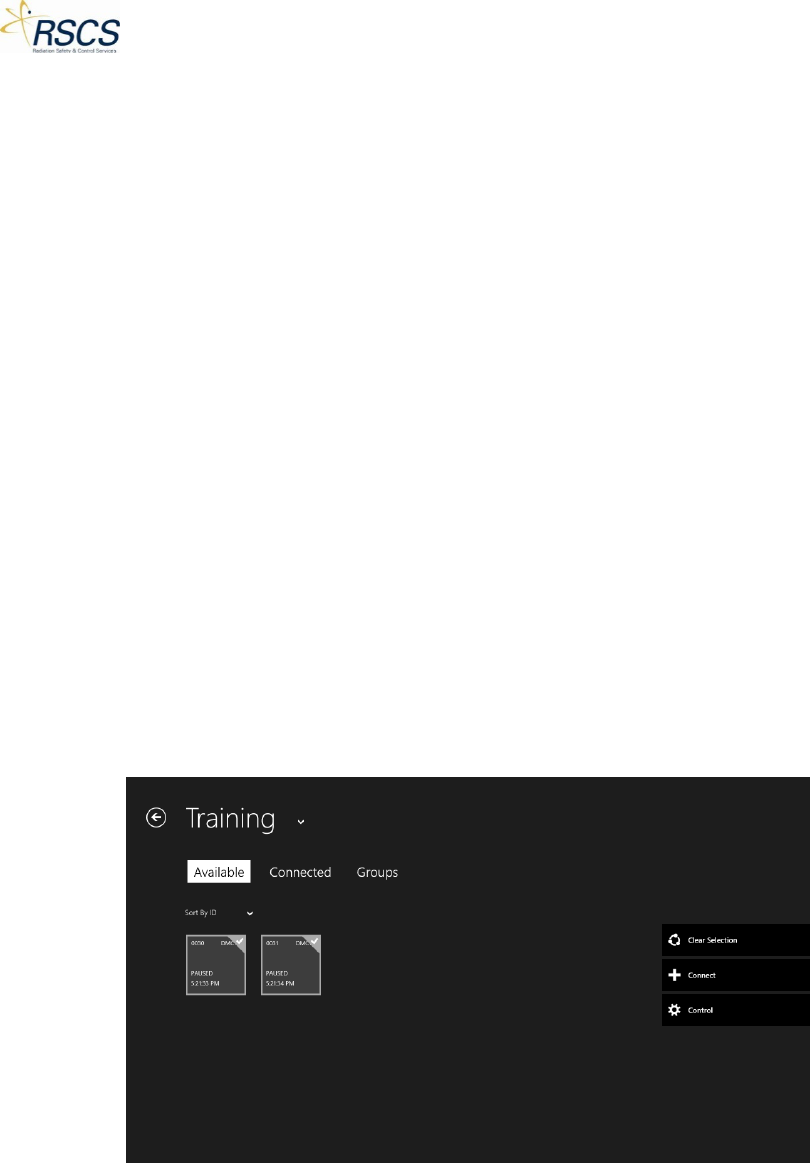
DMC 2000TD OPERATORS MANUAL
To switch from Pause Mode to Active Mode: short press the Selector Button and the display will show
“change”. After five (5) seconds the display will show “enter”. Short press the Selector Button and the
DMC 2000TD will enter Active Mode.
To switch from Active Mode to Pause Mode: Long press the Selector Button for 10 seconds until the
display shows “change” and continue pressing the Selector Button. After and additional three (3)
seconds the display will show “exit”. Quickly let go of the Selector Button and the DMC 2000TD will
switch from Active Mode to Pause Mode.
Fast Entry Mode
Each DMC 2000TD has the ability to work in Fast Entry Mode like a real DMC 2000S. Fast Entry Mode is
set in Configurations (see section 2.3.2) and works for both Satellite Mode and Autonomous Mode. A
DMC 2000TD configured in Fast Entry Mode will maintain the same functionality as a DMC 2000TD in
Satellite or Autonomous Mode but will allow entry to Active Mode with a short press of the Selector
Button on the DMC 2000TD.
Groups
Groups provides the option for the instructor to set a large number of DMC 2000TDs (or any number up
to 32, if desired) to work as a single unit in SCC. This feature is useful for segregating trainees by area or
job function when performing a simulated task.
Note: A Group is most often comprised of multiple DMC 2000TDs; however it is possible to have a single
DMC 2000TD work as a group.
Connecting a Group
1. From the Training Section, select the available DMC 2000TDs to connect to for the group.
2. Touch the Connect button to connect to the selected DMC 2000TDs.
73 REVISION 0
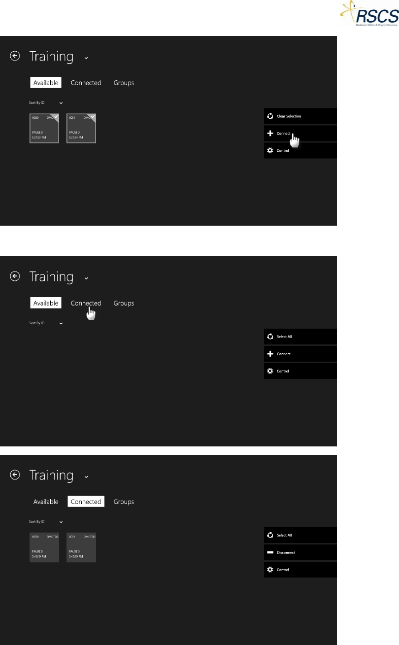
DMC 2000TD OPERATORS MANUAL
3. Touch the Connected tab to change to the Connected Page.
REVISION 0 74
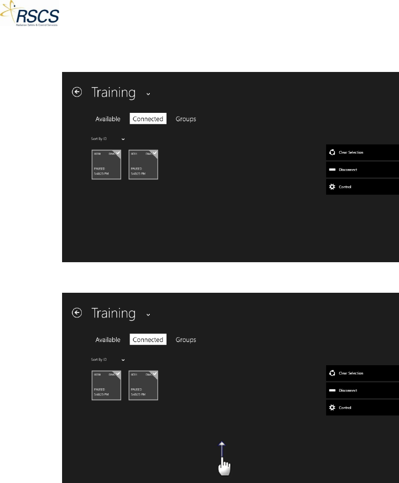
DMC 2000TD OPERATORS MANUAL
4. Touch the individual DMC 2000TD Tiles or use the Select All option to select all the DMC2000TDs
for the Group.
5. Swipe up from the bottom of the screen to reveal the App Bar.
75 REVISION 0
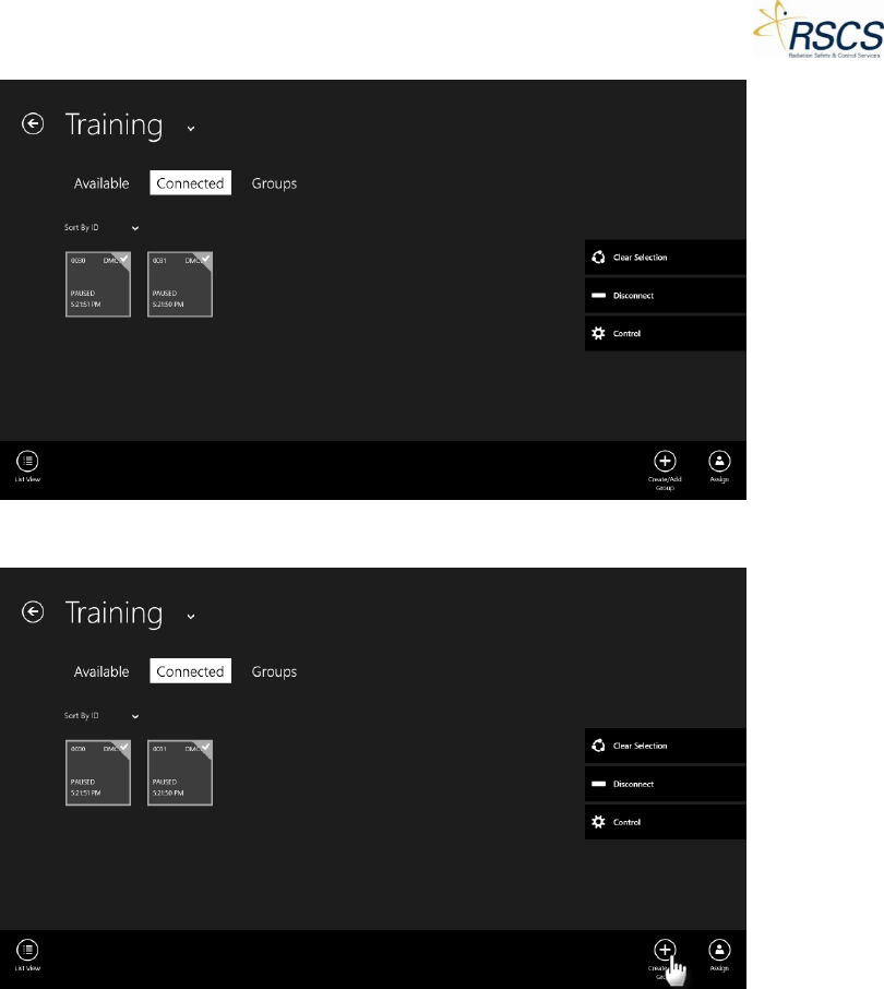
DMC 2000TD OPERATORS MANUAL
6. Touch the Create/Add Group button.
7. A pop up box appears with the option to name the Group or use the next available default name
(e.g. Group A). Touch Save to use that Group name. If desired touch within the text field to
activate the On-Screen keyboard and enter a custom Group name.
REVISION 0 76
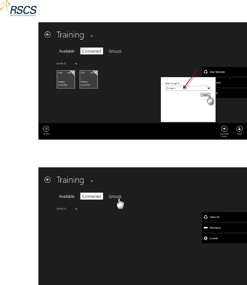
DMC 2000TD OPERATORS MANUAL
8. The selected DMC 2000TDs will move to the Groups Page. Touch the Groups tab to switch to the
Group Page.
9. The selected DMC 2000TDs combine to form a Group (now a blue Tile) with the name selected
in step 7.
77 REVISION 0
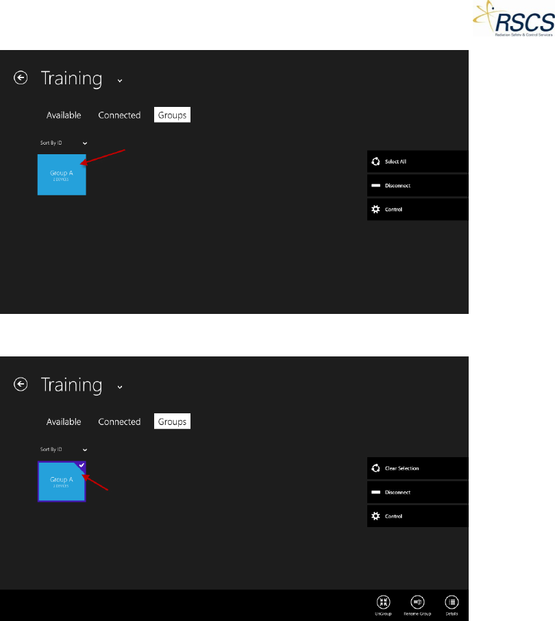
DMC 2000TD OPERATORS MANUAL
10. Select the Group to be controlled.
Note: On the Group Page, the App Bar contains three options; Ungroup, Rename Group, and Details.
a. Ungroup sends the grouped DMC 2000TDs back to the Connected Page.
REVISION 0 78
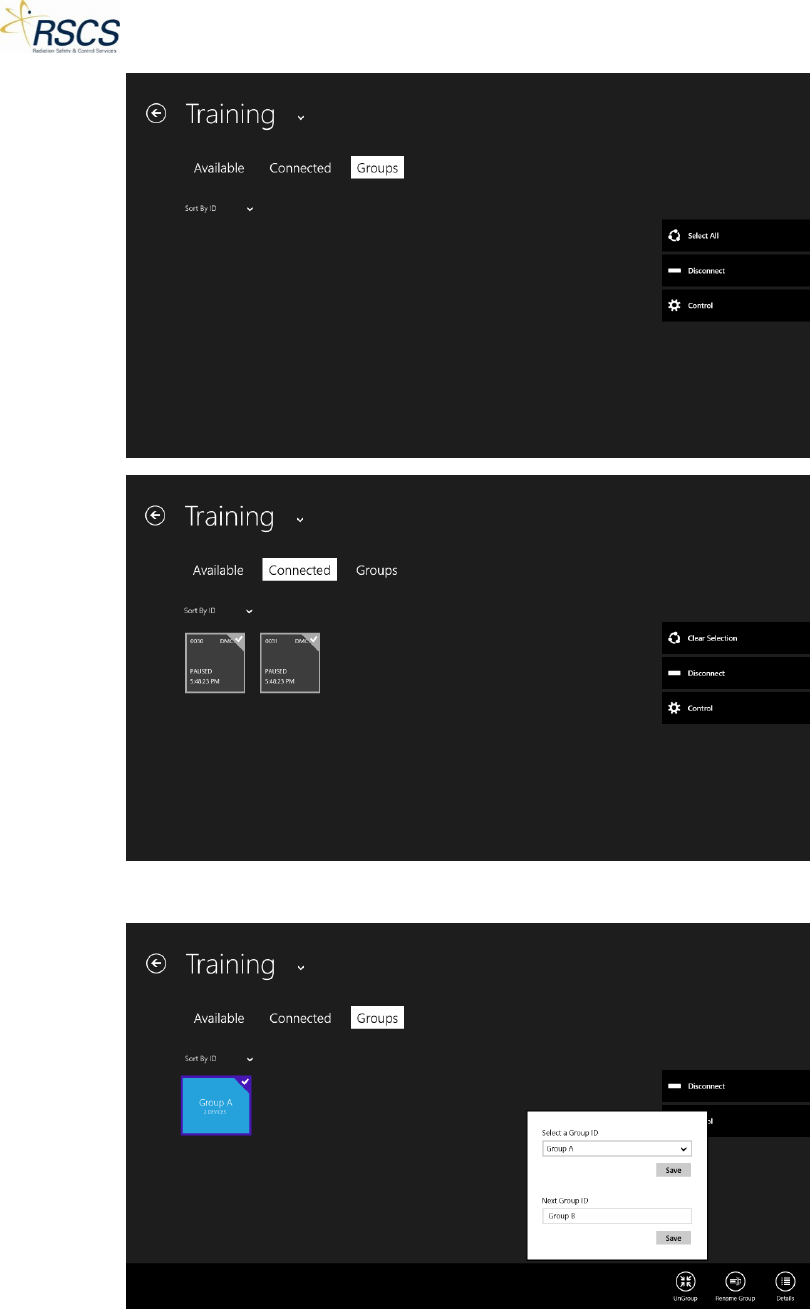
DMC 2000TD OPERATORS MANUAL
b. Rename Group allows for a name change of the selected Group.
c. Details expands the blue Group Tile to show each DMC 2000TD in the Group.
79 REVISION 0
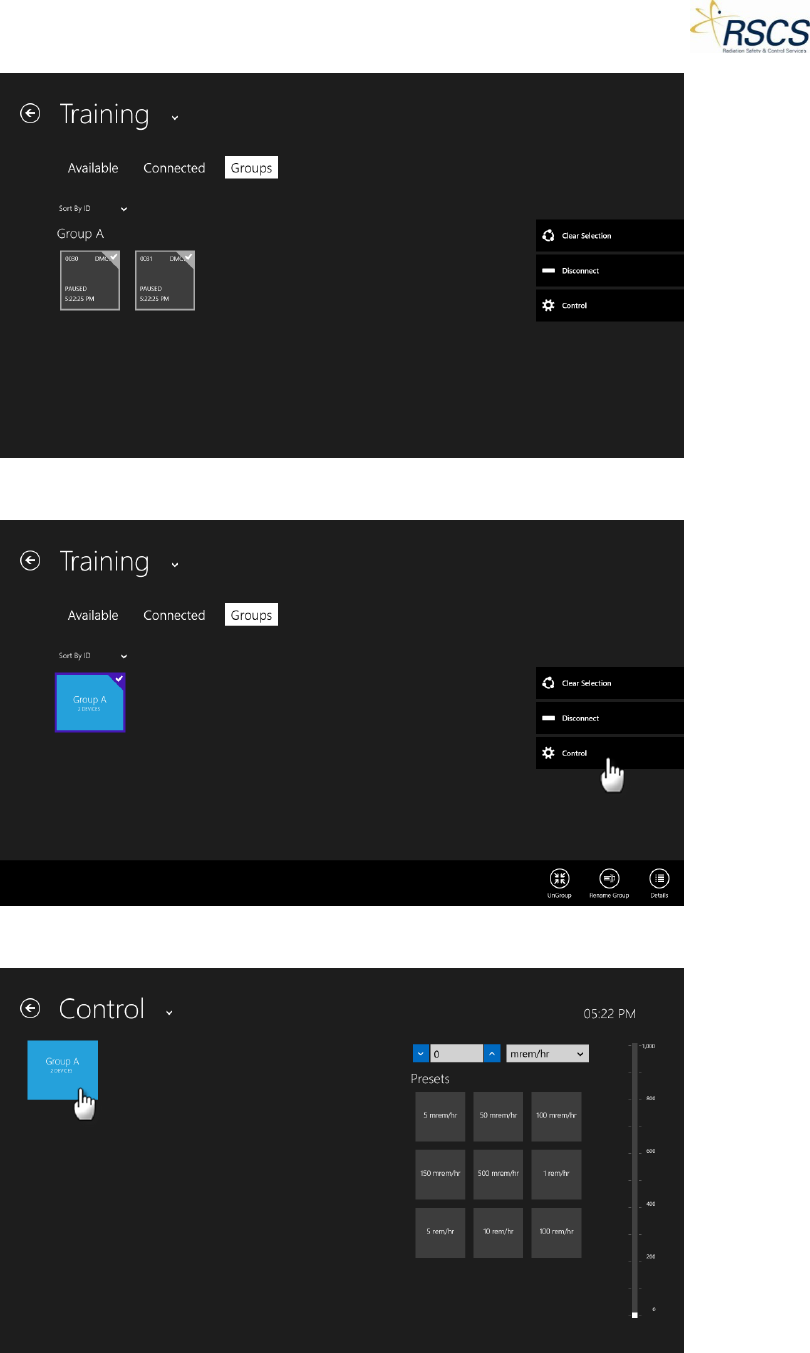
DMC 2000TD OPERATORS MANUAL
11. Touch the Control button to begin Controlling the selected Group.
12. Select the Group to Control by touching the Group Tile.
REVISION 0 80
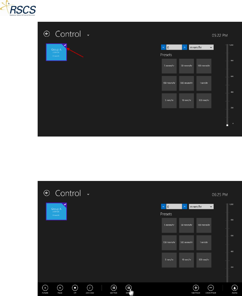
DMC 2000TD OPERATORS MANUAL
13. The functionality of the Group works the same as a single DMC 2000TD in Control. However, a
Group Tile will only show a single Dose Rate for the entire Group. No information about Alarms
is available on the Group Tile. It is possible to view the individual DMC 2000TDs that make up
the Group by swiping up to show the App Bar and selecting Details.
81 REVISION 0
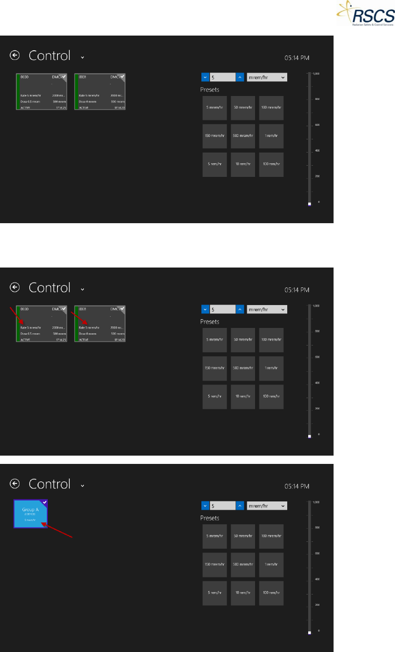
DMC 2000TD OPERATORS MANUAL
14. When all the DMC 2000TDs in a Group have the same Dose Rate, the Group Dose Rate is
displayed on the Group Tile.
REVISION 0 82
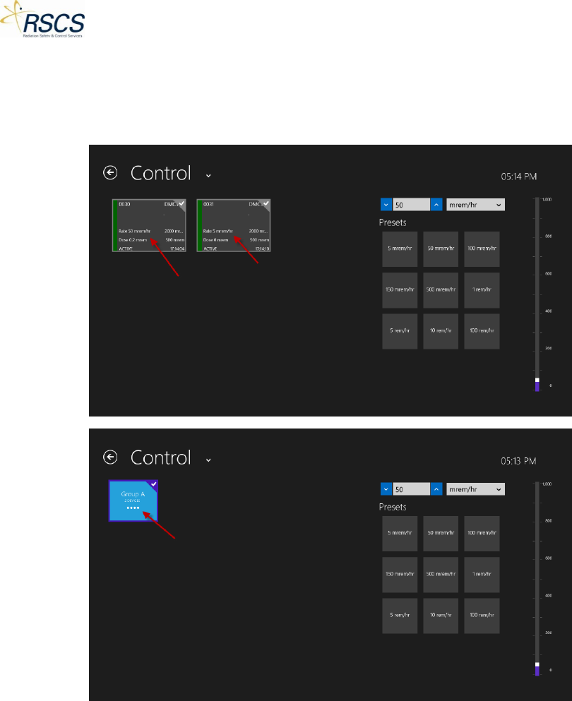
DMC 2000TD OPERATORS MANUAL
15. When at least one DMC 2000TD in the Group has a different Dose Rate than the others, four
dots will appear where the Dose Rate was on the Group Tile. This lets the instructor know that
not every DMC 2000TD is working together as one anymore. This can be fixed using the Details
view.
83 REVISION 0