Radicom Research BPM730CE 20730 class 2 Bluetooth Module User Manual
Radicom Research Inc 20730 class 2 Bluetooth Module
User manual

Radicom BPM730CE series
Bluetooth HID Module Datasheet V1.7
Radicom Research, Inc. reserves the right to amend the document without notice
at any
time.
Radicom assumes no responsibility for any errors appeared in the
document,
and
disclaims any express or implied warranty, relating to sale and/or use
of Radicom
products including liability or warranties relating to fitness for a particular
purpose,
or
Radicom Research, Inc.
Copyright © 2014. All rights
reserved
www.radi.com
Index
1. Introduction
..................................................................................................2
2. Features
........................................................................................................3
3. Product Specifications
................................................................................4
3.1
3.2
3.3
3.4
3.5
3.6
3.7
Function Block Diag
r
am
...................................................................4
Applications Diagram
.………………………………………………….4
Bluetooth Related Specification
.....................................................5
Electronic Character
..........................................................................5
Mechanical Dimension
......................................................................6
Pinout Diagram
..................................................................................7
Pin
Definition
.................................................................................. 8,9
1
4. FCC, IC, and CE Label Location and Module Model identification……...10
5. Important Regulatory Compliance and User Information………………….11
6. Industry Canada statement……………………………………………………...14
7. CE Declaration of Conformity…………………………………………………. ..17
1.
Introduction
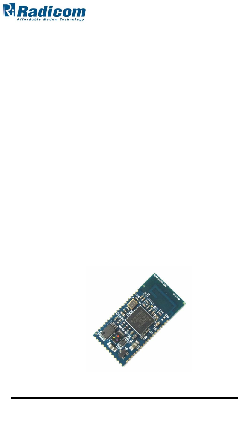
Radicom BPM730CE series is a worldwide Bluetooth Human Interface Device (HID)
module
based on the latest Broadcom BCM20730 Bluetooth chip. It is integrated with
PCB
antenna, serial EEPROM, crystal, and also components for the built-in
switching
regulators to reduce the external BOM
cost.
Radicom BPM730CE series Bluetooth module integrates the entire profile, application,
and
Bluetooth protocol stack and is fully compliant with the Bluetooth SIG specification
for
human interface devices. The BPM730CE series is fully compliant with the version
3.0
Bluetooth
specification, including enhanced power control (Unicast Connectionless
Data), which
is
essential to mouse and keyboard applications in personal
computers.
Integration is the key to achieving the system cost targets of today's PC OEMs.
By
integrating all components within today's mouse and keyboard into the BPM730C
E
series,
low
system costs can be achieved to approach the price points of legacy-wire
d
mice
and
keyboards. The BPM730CE series can interface directly to mouse optical o
r
ball encoders
and
keyboard scan
matrices.
This module is suitable for the following various
applications:
•
•
•
•
•
•
Wireless
keyboards
Wireless pointing devices: mice, track
balls
Game
controllers
Joysticks
Presenter
devices
Remote
controls
Class 2,
BPM730CE series
2
Radicom Research, Inc.
Copyright © 2014. All rights
reserved
www.radi.com

2.
Features
1. Single-chip Bluetooth device with fully integrated Human Interface Device (HID)
profile
and full Bluetooth
stack.
2. On-board ARM processor and RAM/ROM
memory.
3. Custom-integrated Bluetooth core processor has been optimized to support the
HID
V1.0 profile and minimize power
consumption.
4. Bluetooth version 3.0 compliant including support for enhanced power control
(Unicast
Connectionless
Data)
5. Integrate serial EEPROM and contains high-performance boost regulator for
direct
connection with mice
electronics.
6. Built-in switching regulator to reduce external BOM and provide high efficient
power
for external
sensor.
7. On-module serial EEPROM for configuration and patch
code.
8. Supports SPI (full duplex and half duplex) to communicate with mouse
sensor.
9. Direct interface to keyboard scan matrix with full support for up to 8X20 keys
and
user-customized hot
keys.
10. Integrated quadrate signal decoder to support both ball and optical mouse
designs.
11. Direct interface to
LED
12. Approx. 30.6mm x 15mm x 3mm FR4
PCB.
3
Radicom Research, Inc.
Copyright © 2014. All rights
reserved
www.radi.com
3. Product
Specifications
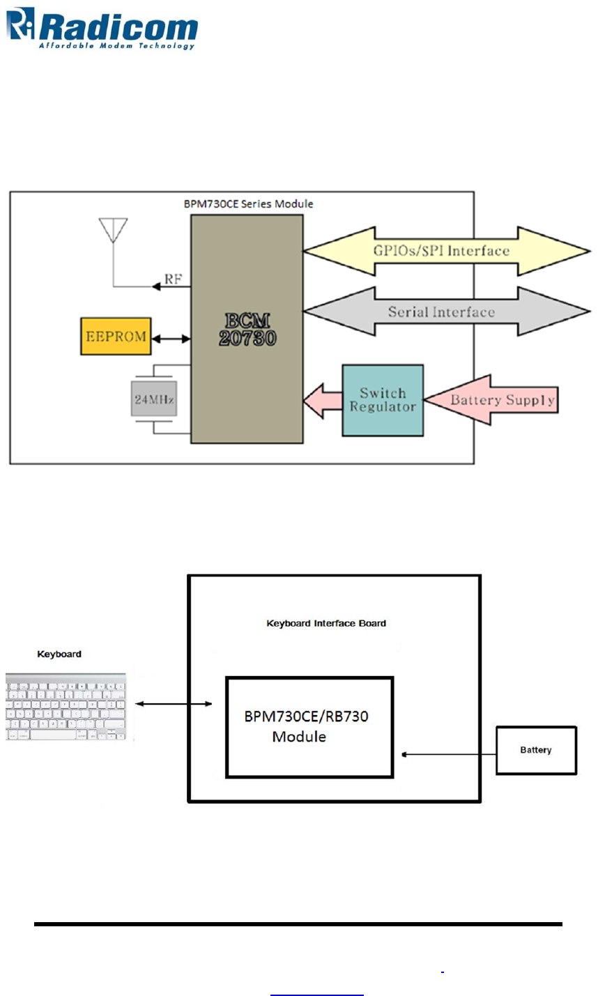
3.1. Function Block Diagram
3.2. Applications Diagram
4
Radicom Research, Inc.
Copyright © 2014. All rights
reserved
www.radi.com
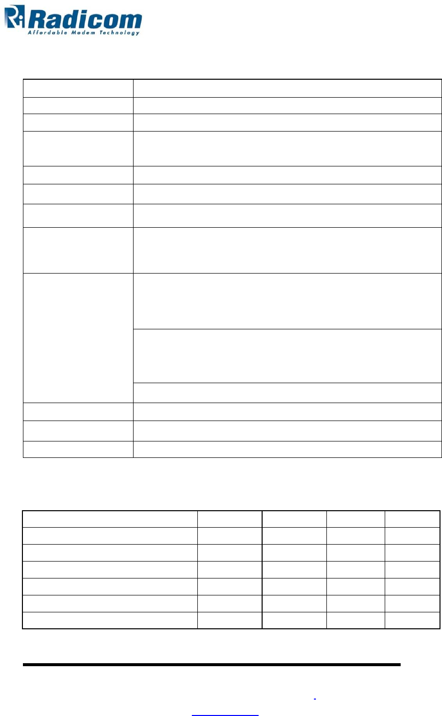
3.3. Bluetooth related Specification
meet FCC and
R&TTE
3.4 Electronic Character
5
Radicom Research, Inc.
Copyright © 2014. All rights
reserved
www.radi.com
Minimum
Typical
Maximum
Unit
Operation
voltage
2.0
3.0
3.6
V
Output
Power
2
dBm
Sensitivity
-84
dBm
Key scan active mode,
VBAT=3V
2.5
mA
Sniff Mode, 100mS,
VBAT=3V
0.78
mA
Deep sleep,
VBAT=3V
40
uA
Wireless
Bluetooth v3.0 Class 2
(Broadcom20730chip)
Data
Rate
Bluetooth v3.0
(1Mbps)
Bandwidth
2.402GHz – 2.480
GHz
RF output
power
Bluetooth class 2 ( up to +2dBm
)
Sensitivity
Bluetooth class 2 ( down to
-84dBm)
Spread
Spectrum
Frequency Hopping Spread Spectrum
(FHSS)
Modulation
method
GFSK
Operation
Range
Up to 10M (open
space)
Note: The maximum operating range depends on the paired PC or Rx
dongle performance, battery power, and environmental factors
System
IBM PC Pentium 233 or
Above.
Linux and Mac are also acceptable i.e. PowerMac 10.1
/
PowerPC G4(1.2) or
Above.
Win2000/ WinXP/ Vista/
Win7
(Support WinXP SP2, Widcomm BTW, Toshiba Stack or
IVT
BlueSoleil Bluetooth
Softwares)
Bluetooth USB dongle or Bluetooth-enabled
PC
Storage
Temp.
-40
°
C~125
°
C
Operation
Humidity
10%~90%(55±2%)
Operation
Temp.
-20
°
C
~
+70
°
C
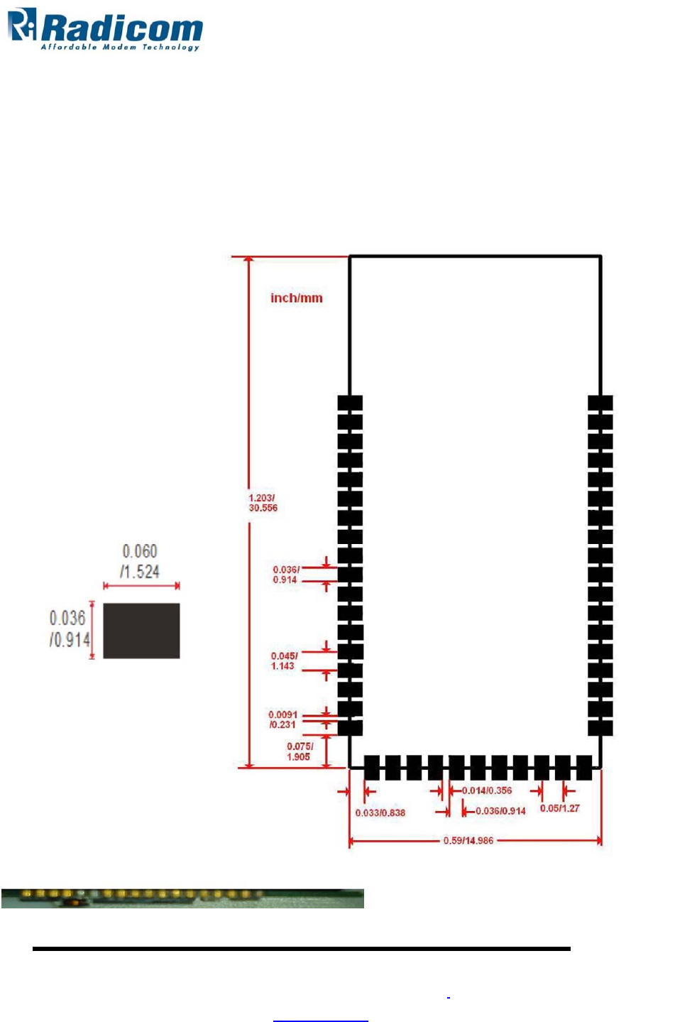
3.5 Mechanical Dimension
Top side
view:
Board size = 30.556 mm x 14.986
mm
Pitch of short side = 1.27
mm
Pitch of long side = 1.143
mm
Pad width = 0.914
mm
Module
Height
Maximum height = 3.0
mm
Board thickness = 0.80
mm
6
Radicom Research, Inc.
Copyright © 2014. All rights
reserved
www.radi.com
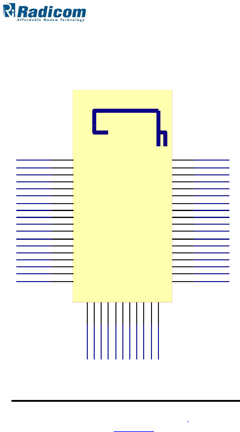
3.6 Pinout Diagram
GND
47
MOSI
7
Radicom Research, Inc.
Copyright © 2014. All rights
reserved
www.radi.com
P
24
P0
SDA
P
13
P
19
P
25
S
CL
P
20
V
BA
T
P
18
P
14
GND
GND
P35
GND
P9
P32
P8
P38
P36
P12
P22
P10
P23
P17
P1
P16
P3
P11
G8
NC
P21
P26
P2
P27
H5
3P0V
G5
P33
P6
P28
P7
P29
P4
P15
P5
GND
1
GND
2
GND
P3 5 /ADC
46
P9
45
3
P32
4
P38/
P8
44
5
P12
P36/
S
C
L
K
/ADC
43
6
P10
P22
42
7
P17
P23
41
8
P16
P1
40
9
P11
P3
39
10
N
C
RE
S
ET
_
N
38
11
P26
P21
37
12
P27
P2
36
13
3P0V
U
A
RT
_
RX
35
U
A
RT
_
TX
34
14
P33
15
P28
P6
33
16
P29
P7
32
17
P15
P4
31
18
GND
P5
30
P
24
29
P0
28
SD
A
27
P
13
26
P
19
25
P
25/MIS
O
24
S
CL
23
P
20
22
V
BA
T
21
P
18
20
P
14
19

3.7 Pin Definition
Pin No. Pin Name I/O Description
01 GND Power System ground
02 GND Power System ground
03 P32
I/O Port 32
04 P38/MOSI I/O / O Port 38 / MOSI for SPI Interface
05 P12 I/O Port 12
06 P10 I/O Port 10
07 P17 I/O Port 17
08 P16 I/O Port 16
09 P11 I/O Port 11
10 NC Module internal connection for write protection
11 P26 I/O Port 26
12 P27 I/O Port 27
13 3P0V Power 3V power output
14 P33 I/O Port 33
15 P28 I/O Port 28
16 P29 I/O Port 29
17 P15 I/O Port 15
18 GND Power System ground
19 P14 I/O Port 14
20 P18 I/O Port 18
21 VBAT Power Battery power supply
22 P20 I/O Port 20
23 SCL O SCL for I²C Interface
24 P25/MISO I/O / I Port 25 / MISO for SPI Interface
25 P19 I/O Port 19
26 P13 I/O Port 13
27 SDA I/O SDA for I²C Interface
28 P0 I/O Port 0
29 P24 I/O Port 24
30 P5 I/O Port 5
8
Radicom Research, Inc.
Copyright © 2014. All rights
reserved
www.radi.com

31 P4 I/O Port 4
32 P7 I/O Port 7
33 P6 I/O Port 6
34 UART_TX O Debug UART transmit port
Debug UART receiver port. After power on reset, if
UP_RX =1, firmware download mode UP_RX=0,
normal mode
35 UART_RX I
36 P2 I/O Port 2
37 P21 I/O Port 21
38 RESET_N I Active low system reset with a weak pull up.
39 P3 I/O Port 3
40 P1 I/O Port 1
41 P23 I/O Port 23
42 P22 I/O Port 22
43 P36/SCLK/ADC I/O / O / I Port 36 / SCLK for SPI Interface / Battery Detector Input
44 P8 I/O Port 8
45 P9 I/O Port 9
46 P35/ADC I/O / I Port 35 / Battery Detector Input
47 GND Power System ground
P.S. CS for SPI interface could be configured by any PIOs except module Pin 4, 23,
24,
27 and
43.
9
Radicom Research, Inc.
Copyright © 2014. All rights
reserved
www.radi.com
Radicom Research, Inc.
Copyright © 2014. All rights
reserved
www.radi.com
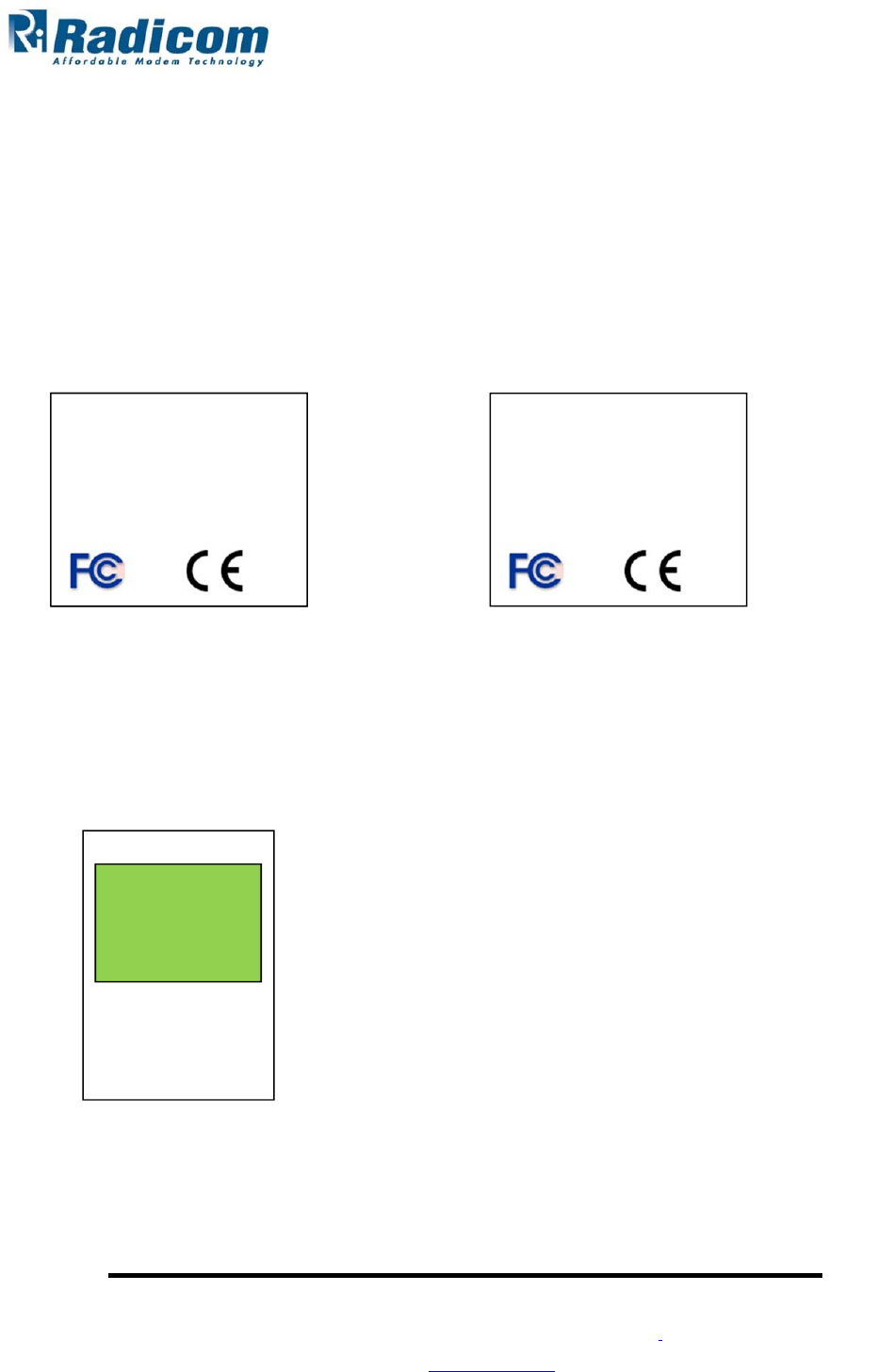
4. FCC & IC Label and Model Identification
The BPM730CE module family is FCC Part 15 and IC (Industry Canada) certified. The
BPM730CE is also CE marked. The modules are labeled with the BPM730CE module
model number and FCC Part 15 ID, IC registration number and CE mark. The label can
be found on top of the metal shielding on the BPM730CE Module.
Location:
Radicom Research Inc.
Model: BPM2001
FCC ID: K7T-BPM2001
IC: 2377A-BPM2001
Label
Module board
Radicom Research Inc.
Model: RB730
FCC ID: K7T- BPM730CE
IC: 2377A- BPM730CE
Radicom Research Inc.
Model: BPM2001
FCC ID: K7T-BPM2001
IC: 2377A-BPM2001
Radicom Research Inc.
Model: BPM730CE
FCC ID: K7T- BPM730CE
IC: 2377A- BPM730CE
10

Radicom Research, Inc.
Copyright © 2014. All rights
reserved
www.radi.com
5. Federal Communication Commission Interference Statement
This equipment has been tested and found to comply with the limits for a Class B digital
device, pursuant to Part 15 of the FCC Rules. These limits are designed to provide
reasonable protection against harmful interference in a residential installation. This
equipment generates, uses and can radiate radio frequency energy and, if not installed and
used in accordance with the instructions, may cause harmful interference to radio
communications. However, there is no guarantee that interference will not occur in a
particular installation. If this equipment does cause harmful interference to radio or
television reception, which can be determined by turning the equipment off and on, the
user is encouraged to try to correct the interference by one of the following measures:
- Reorient or relocate the receiving antenna.
- Increase the separation between the equipment and receiver.
- Connect the equipment into an outlet on a circuit different from that
to which the receiver is connected.
- Consult the dealer or an experienced radio/TV technician for help.
FCC Caution: Any changes or modifications not expressly approved by the party
responsible for compliance could void the user's authority to operate this equipment.
This device complies with Part 15 of the FCC Rules. Operation is subject to the
following two conditions: (1) This device may not cause harmful interference, and (2)
this device must accept any interference received, including interference that may
cause undesired operation.
11

IMPORTANT NOTE:
FCC Radiation Exposure Statement:
The product comply with the US portable RF exposure limit set forth for an uncontrolled
environment and are safe for intended operation as described in this manual. The further
RF exposure reduction can be achieved if the product can be kept as far as possible from
the user body or set the device to lower output power if such function is available.
This transmitter must not be co-located or operating in conjunction with any other antenna
or transmitter.
This device is intended only for OEM integrators under the following conditions:
1) The transmitter module may not be co-located with any other transmitter or antenna,
As long as 1 condition above is met, further transmitter test will not be required.
However, the OEM integrator is still responsible for testing their end-product for any
additional compliance requirements required with this module installed
IMPORTANT NOTE
In the event that these conditions can not be met (for example certain laptop
configurations or co-location with another transmitter), then the FCC authorization is no
longer considered valid and the FCC ID can not be used on the final product. In these
circumstances, the OEM integrator will be responsible for re-evaluating the end product
(including the transmitter) and obtaining a separate FCC authorization.
12

Radicom Research, Inc.
Copyright © 2014. All rights
reserved
www.radi.com
End Product Labeling
The final end product must be labeled in a visible area with the following:
“Contains FCC ID: K7T- BPM730CE
Manual Information to the End User
The OEM integrator has to be aware not to provide information to the end user regarding
how to install or remove this RF module in the user’s manual of the end product which
integrates this module.
The end user manual shall include all required regulatory information/warning as show
in this manual.
13

Radicom Research, Inc.
Copyright © 2014. All rights
reserved
www.radi.com
6. Industry Canada statement:
This device complies with Industry Canada licence-exempt RSS standard(s). Operation is
subject to the following two conditions:
(1) this device may not cause interference, and
(2) this device must accept any interference, including interference that may cause
undesired operation of the device.
Le présent appareil est conforme aux CNR d'Industrie Canada applicables aux appareils
radio exempts de licence. L'exploitation est autorisée aux deux conditions suivantes :
(1) l'appareil ne doit pas produire de brouillage, et
(2) l'utilisateur de l'appareil doit accepter tout brouillage radioélectrique subi, même si le
brouillage est susceptible d'en compromettre le fonctionnement.
Radiation Exposure Statement:
The product comply with the Canada portable RF exposure limit set forth for an
uncontrolled environment and are safe for intended operation as described in this manual.
The further RF exposure reduction can be achieved if the product can be kept as far as
possible from the user body or set the device to lower output power if such function is
available.
Déclaration d'exposition aux radiations:
Le produit est conforme aux limites d'exposition pour les appareils portables RF pour les
Etats-Unis et le Canada établies pour un environnement non contrôlé. Le produit est sûr
pour un fonctionnement tel que décrit dans ce manuel. La réduction aux expositions RF
peut être augmentée si l'appareil peut être conservé aussi loin que possible du corps de
l'utilisateur ou que le dispositif est réglé sur la puissance de sortie la plus faible si une telle
fonction est disponible.

Radicom Research, Inc.
Copyright © 2014. All rights
reserved
www.radi.com
This device is intended only for OEM integrators under the following conditions:
1) The transmitter module may not be co-located with any other transmitter or antenna.
As long as 1 condition above are met, further transmitter test will not be required. However,
the OEM integrator is still responsible for testing their end-product for any additional
compliance requirements required with this module installed.
Cet appareil est conçu uniquement pour les intégrateurs OEM dans les conditions
suivantes:
1) Le module émetteur peut ne pas être coïmplanté avec un autre émetteur ou antenne.
Tant que les 1 condition ci-dessus sont remplies, des essais supplémentaires sur l'émetteur
ne seront pas nécessaires. Toutefois, l'intégrateur OEM est toujours responsable des essais
sur son produit final pour toutes exigences de conformité supplémentaires requis pour ce
module installé.
IMPORTANT NOTE:
In the event that these conditions can not be met (for example certain laptop configurations
or co-location with another transmitter), then the Canada authorization is no longer
considered valid and the IC ID can not be used on the final product. In these circumstances,
the OEM integrator will be responsible for re-evaluating the end product (including the
transmitter) and obtaining a separate Canada authorization.
NOTE IMPORTANTE:
Dans le cas où ces conditions ne peuvent être satisfaites (par exemple pour certaines
configurations d'ordinateur portable ou de certaines co-localisation avec un autre émetteur),
l'autorisation du Canada n'est plus considéré comme valide et l'ID IC ne peut pas être
utilisé sur le produit final. Dans ces circonstances, l'intégrateur OEM sera chargé de
réévaluer le produit final (y compris l'émetteur) et l'obtention d'une autorisation distincte au
Canada.

Radicom Research, Inc.
Copyright © 2014. All rights
reserved
www.radi.com
End Product Labeling
The final end product must be labeled in a visible area with the following:
Contains IC: 2377A- BPM730CE
Plaque signalétique du produit final
Le produit final doit être étiqueté dans un endroit visible avec l'inscription suivante:
Contient des IC: 2377A- BPM730CE
Manual Information to the End User
The OEM integrator has to be aware not to provide information to the end user regarding
how to install or remove this RF module in the user’s manual of the end product which
integrates this module.
The end user manual shall include all required regulatory information/warning as show in
this manual.
Manuel d'information à l'utilisateur final
L'intégrateur OEM doit être conscient de ne pas fournir des informations à l'utilisateur final
quant à la façon d'installer ou de supprimer ce module RF dans le manuel de l'utilisateur du
produit final qui intègre ce module.
Le manuel de l'utilisateur final doit inclure toutes les informations réglementaires requises
et avertissements comme indiqué dans ce manuel.
15
Radicom Research, Inc.
Copyright © 2014. All rights
reserved
www.radi.com
7. CE Declaration of Conformity
For the following equipment:
Radicom Research Inc. Wi-Fi Module
Mode(s): BPM730CE, RB730
are herewith confirmed to comply with the requirements set out in the Council (European
parliament) Directive on the Approximation of the Laws of the
Member States relating to Electromagnetic Compatibility of Radio and Telecom device
(1999/5/CE).
For the evaluation regarding this Directive, the following standards were applied:
EN 300328 V1.8.1: 2012
EN 62311:2008(MPE)
EN 301489-1 V1.9.2:2011
EN 301489-17 V2.2.1:2012
EN 60950-1:2006+A11:2009+A1:2010+A12:2011
This equipment is marked with and can be used throughout the European
community.
Europe – R&TTE Compliance Statement:
Hereby, Radicom Research Inc. declares that this equipment complies with the essential
requirements
and other relevant provisions of DIRECTIVE 1999/5/CE OF THE EUROPEAN
PARLIAMENT
AND THE COUNCIL of March 9, 1999 on radio equipment and telecommunication
terminal Equipment and the mutual recognition of their conformity (R&TTE).
17