Radicom Research WIFIHU2 USB WiFi Module User Manual Ethan Frome
Radicom Research Inc USB WiFi Module Ethan Frome
Users Manual
Radicom Research, Inc.
Preliminary
Designers Guide for the
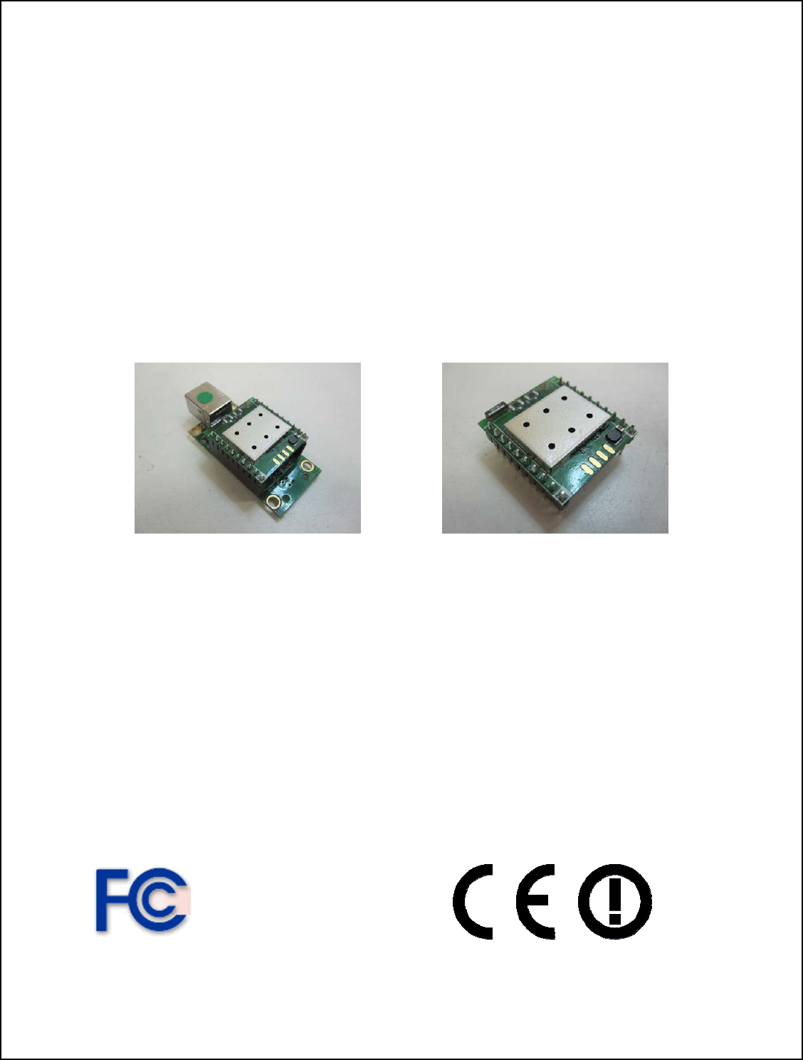
WiFiHU2-NE and WiFiHU2
RoHS Compliant
USB WiFi Modules
April 17, 2012
Table of Contents
tion and Features 3
Ratings and Block Diagram 4
nd Ordering Information 5
onnecting the WiFiHU2 or WiFiHU2-NE to Your System 7
Mechanical Specification and Pin Orientation for the WiFiHU2 8
echanical Specification ~ WiFiHU2-c-1-NE + WiFiHU2-a-1-NE 9
WiFiHU2 USB Interface Pins 10
Additional Information on the Interface Signals 11
FCC, IC, and CE Label Location and Module Model Identification 12
Important Regulatory Compliance and User Information 13
E Declaration of Conformity 16
WiFiHU2 Regulatory Domain Frequencies 17
Driver Installation Guide For Windows XP/2K 18
iFiHU2 USB Linux Driver Quick Installation Guide 20
Warranty 21
Contacting Radicom Research 23
Introduc
Model a
C
M
C
W
Limited
Information furnished by Radicom Research is believed to be accurate and reliable. However
Radicom Research assumes no responsibility for its use, or any infringement of patents or other
rights of third parties that may result from its use. Radicom Research reserves the right to change
2
circuitry at any time without notice. This document is subject to change without notice.

Introduction
Thanks for purchasing Radicom Res Module. Radicom is committed to
ce
Features
• Compatible with both USB 1.1 and USB 2.0 host controllers
le Interface
s transmit PHY rate using 20MHz bandwidth
ification
ile operating at 802.11n data rates
A)
mance when using dual antennas
existence
MAC identities when used as a wireless
• Supports Wake-On-WLAN via Magic Packet and Wake-up frame
rsting for higher
•
K, CCK modulation with long and short preamble
eceive paths. Switch diversity used
•
o trade quantization noise against
increased probability of clipping
• Fast receiver Automatic Gain Control (AGC)
earch’s USB WiFi
providing quality service and technical support in order to expedite the product
development process. The WiFiHU2 Module requires only a USB (Universal Serial Bus)
interface to add state of the art data WiFi wireless operation to any system. It is designed
to fully support IEEE802.11n™ Draft 2.0, IEEE802.11e™ and IEEE802.11i™
standards. If further information is required, please contact us and we will provide any
additional help needed. The WiFiHU2 series offers Soft AP support. It can turn your
Internet connected PC or Laptop into a WiFi Wireless Access Point. So any WiFi devi
such as iPhone, iPod, PDA, within range can connect to Internet by sharing your
WiFiHU2 Access Point.
• Soft AP support (Software enabled Access Point)
• Supports ACCESS Point (Host WiFi)
• USB 2.0 Compatible Hot Swappab
• IEEE 802.11b/g/n compatible WLAN
• 150Mbps receive PHY rate and 75Mbp
• 300Mbps receive PHY rate and 150Mbps transmit PHY rate using 40MHz bandwidth
• 20MHz and 40MHz bandwidth transmission
• Operates in 2.4GHz Frequency Range
• Compatible with 802.11n draft 2.0 spec
• Backward compatible with 802.11b/g devices wh
• Frame aggregation for increased MAC efficiency (A-MSDU, A-MPDU)
• Low latency immediate High-Throughput Block Acknowledgement (HT-B
• Long NAV for media reservation with CF-End for NAV release
• PHY-level spoofing to enhance legacy compatibility
• MIMO power saving mechanism and increased perfor
• 2 x 2 MIMO technology for extended reception robustness and exceptional throughput
• Two Transmit and Two Receive paths (2T2R) with 2.UFL TX/RX antenna ports
• Hardware antenna diversity
• Channel management and co-
• Multiple BSSID feature allows multiple
bridge
• Transmit Opportunity (TXOP) Short Inter-Frame Spaces (SIFS) bu
multimedia bandwidth
Short Guard Interval (400ns)
• DSSS with DBPSK and DQPS
• OFDM with BPSK, QPSK, 16QAM, and 64QAM modulation
Convolutional Coding Rate: 1/2, 2/3, 3/4, and 5/6
• OFDM receive diversity with MRC using up to 2 r
for DSSS/CCK
Selectable digital transmit and receive FIR filters
3
• Programmable scaling in transmitter and receiver t
provals Ap
R), 47 CFR FCC Part 15
Subpart C 15.247, 47 CFR FCC Part 15 Subpart B 2009 (Class B)
2, IC ES-003 issue 4, IC RSS-210 issue 8:2010
• CE Marked: EN 61000-3-2:2006+A2:2009, EN 62311:2008, EN 300 328 V1.7.1,
301 489-17 V2.1.1)
A11:2009+A1:2010+A12:2011
/n compatible WLAN
IEEE 802.11e QoS Enhancement (WMM)
EE 802.11h TPC, Spectrum Measurement
curity ~ Open, shared key, and pair-wise
• FCC Part 15: FCC OET 65 Supplement C (SA
• IC RSS-10
• RoHS Compliant
EN 301 489-1, V1.8.1, EN 61000-3-3:2008, EN
• EN 60950-1:2006+
Support
• IEEE 802.11b/g
•
• IE
• IEEE 802.11i (WPA, WPA2, WEP). Se
key authentication services
• Cisco Compatible Extensions (CCX4)
Ratings
Parameter Min Typical Max Units
Maximum Data Rate 300M bps
Operating Temperature HU °
-40 +85 ° °C
Relative Humidity (non-condensing) 5 % 95 %
USB Power 5V + 10%
Current Consumption 152 155 162 mA
Transmit & Receive Level -84(Rx) +17 (Tx) dBm
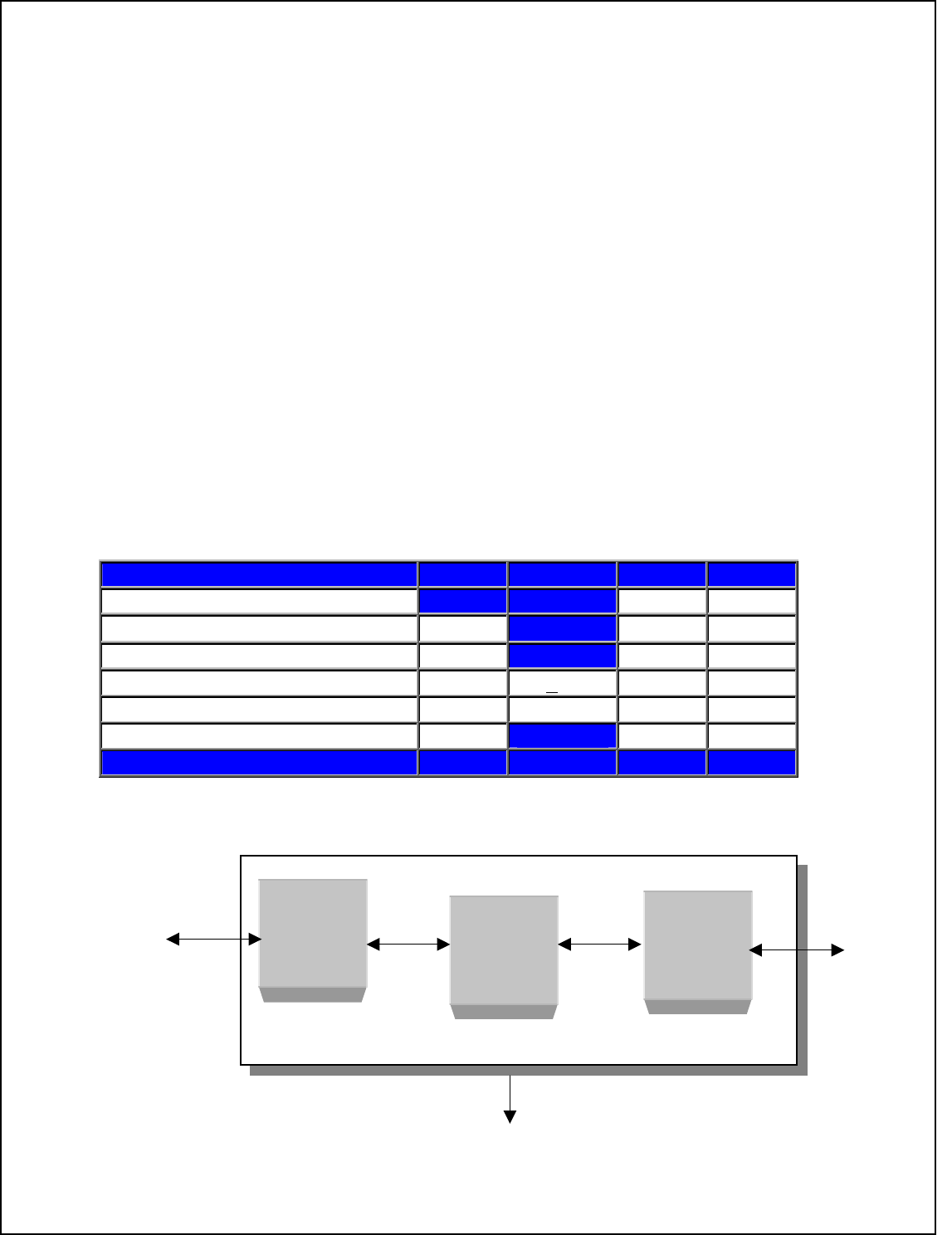
Block Diagram
USB MAC
RF
USB
Port Antenna
USB MODULE
GND
4
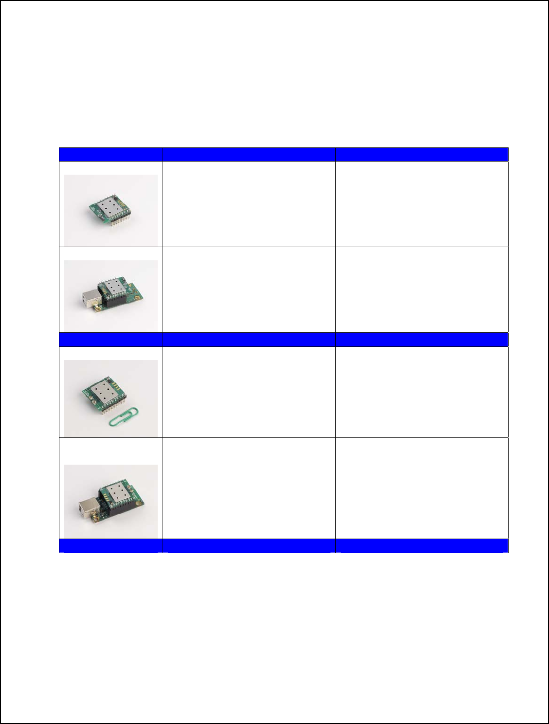
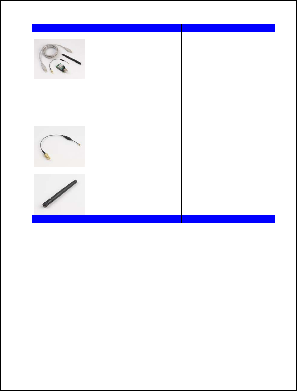
Model and Ordering Information
This versatile WiFiHU2 USB fam
meet the specific syst te of the art WiFi
ily of products offers various configuration options to
em requirements a designer may need to add sta
USB operation. The WiFiHU2 is available as a module, a module with USB Jack and
antennae interface, or as a complete external device in an enclosure. The WiFiHU2 also
has many different antennae options.
Model Description Comments
WiFiHU2-a WiFi USB Module with dual on
board chip Uses onboard chip antennae.
Not for use al
ment.
antennae with Extern
Antenna. Allows designer to
determine USB Jack place
WiFiHU2-a-1-NE WiFiHU2-a installed in a
WiFiHU2-CB1 Carrier Board Complete WiFi Module with
dual chip antennae with USB
with on board USB Jack. Jack interface.
WiFiHU2-c * WiFi USB Module with two
MD Connectors for attaching
Allows designer to determine
SB Jack and antenna
S
antenna cables and 2.4GHz 2
dBi Omni-directional antennas
U
placement. Can use one or two
cables and antennas
WiFiHU2-c-1-
NE* WiFiHU2-c installed in
WiFiHU2-CB1 Carrier Board
.
Complete WiFi Module for 2
cables and 2 antennas with USB
with on board USB Jack Jack interface.
These models can u e ither one or two cables and antennas. For ultimate performance, we
commend using two antennas to meet MIMO requirement with better adaptability for
* s e
re
receiving.
5
WiMDK-2001 Complete WiFiHU2
evelopment kits including
talled in
k
also
WiMDK-2001-a Kit for
odel WiFiHU2-a-1-NE
odel WiFiHU2-c-1-NE
d
WiFiHU2 module ins
Carrier Board with USB jac
interface. All kits include 6ft
USB cable, and CD with
Designers Guide and Drivers.
Antennas and Cables are
provided for external antenna
models.
M
WiMDK-2001-c Kit for
M
AC6i-RP-SMA
6" U.FL. to RP-SMA female
onnector antenna cable Antenna Cable for models
WiFiHU2-c and WiFiHU2-c-1-cNE
ATN-2d-RP-SMA Replacement antenna, 2.4GHz,
2dBi, RP-SMA, Omni- Antenna for models WiFiHU2-c
and WiFiHU2-c-1-NE
directional.
6

Connecting the WiFiHU2 or WiFiHU2-NE to Your System
rior to connecting the WiFiHU2 to a Window XP, the drivers should be installed. The
iFiHU2 Modules are designed for easy connection to any standard USB Port and
even
E
ounted onto a USB hub PCB (WiFiHU2-NE). To remove the
y
ance, we recommend using two antennas to meet MIMO
st
sest
P
W
wireless network. Connect one end of the USB cable into the USB connector on the
WiFiHU2-NE and the other into any available USB receptacle on your computer. The
WiFiHU2-NE’s “Hot Swap-able” interface allows you to plug or unplug the module
when the computer is on. If using Windows, load the provided drivers. The WiFiHU2-N
is now ready for use.
If you plan to embed the WiFiHU2 into your system, the initial evaluation consists of the
iFiHU2 USB Module mW
WiFiHU2 carefully remove it from the two 8 pin headers on the WiFiHU2-NE USB
interface board. Save this interface board. The WiFiHU2 can always be reinstalled into
the WiFiHU2-NE USB interface board and connected to any standard USB port to verif
or test the module functions.
If you use external antenna, connect one end of Radicom approved antenna to the on
oard socket. For ultimate performb
requirement with exceptional reception and throughput. If only using one antenna, you mu
use the correct antenna socket for good performance. Connect single antenna to the socket clo
to the Radicom Research white silkscreen legend on the PCB.
7
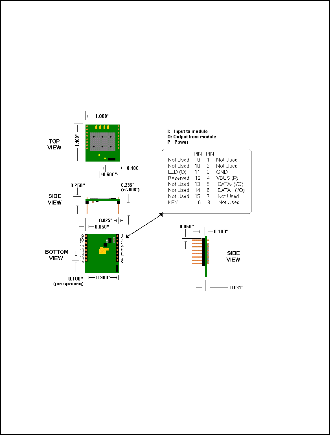
Mechanical Specification and Pin Orientation for the WiFiHU2
The WiFiHU2 USB Half Inch Modules are designed for easy connection to any standard
SB interface and wireless network. The connection is made through two 8-pin headers, U
hich may be attached to your device via a socket or by individually hardwiring each w
pin.
Notes:
1. Pin Spacing is 0.100 inch from center to center
2. Dimension of the WiFiHU2 module – 1.10 x 1.00 x 0.25 inch
Suggested mating female connector:
oHS Thru-Hole)
)
3.
Samtec P/N. #SSW-108-21-G-S (R
Samtec P/N. #SSW-108-22-G-S-VS (RoHS SMT
4. Square pins – 0.025 x 0.025 inch
8
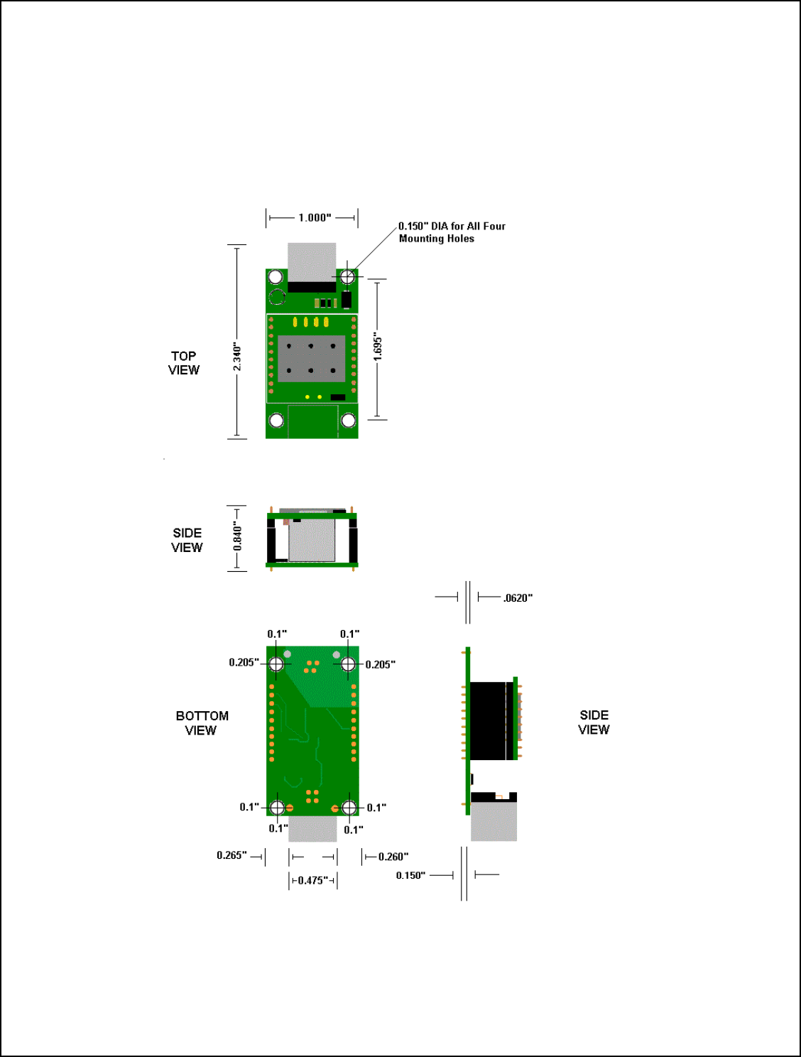
Mechanical Specification for the
WiFiHU2-c-1-NE and WiFiHU2-a-1-NE
9
WiFiHU2 USB Interface Pins
The following shows the I/O Pins required for adding the WiFiHU2 USB Module to your
embedded system.
PIN Number Name Type
1 Not Used
2 Not Used
3 GND Ground
4 VBUS USB Power
5 DATA- Input / Output
6 DATA+ Input / Output
7 Not Used
8 Not Used
9 Not Used
10 Not Used
11 LED (O) Output
12 Reserved
13 Not Used
14 Not Used
15 Not Used
16 Key No Pin
10

Additional Information on the Interface Signals
PIN Name Definition _____
1,2 Not used – No Connection can be used for mounting purposes
3 GND – Ground – Connect this pin to the ground of the USB bus
4 VBUS – This is the USB Power Connection. Connect this pin to VBUS
5 *DATA (-) - Connect this pin to Data –
6 *DATA (+) - nnect th Data + Co is pin to the
7,8,9,10 Not used – No Connection can be used for mounting purposes
11 LED - Link Process
12 Reserved
13,14,15 Not used – N onnecti sed for m o C on can be u ounting purposes
16 No Pin – Thi has be . Add a k y to the mating connector to s Pin en removed e
prevent the m le fromodu being plugged in backwards.
*
11
Note: D+ (Pin 15) and D- (Pin 16) are the differential data plus and minus signals
of the USB port. The two traces should be in parallel and equal in length.
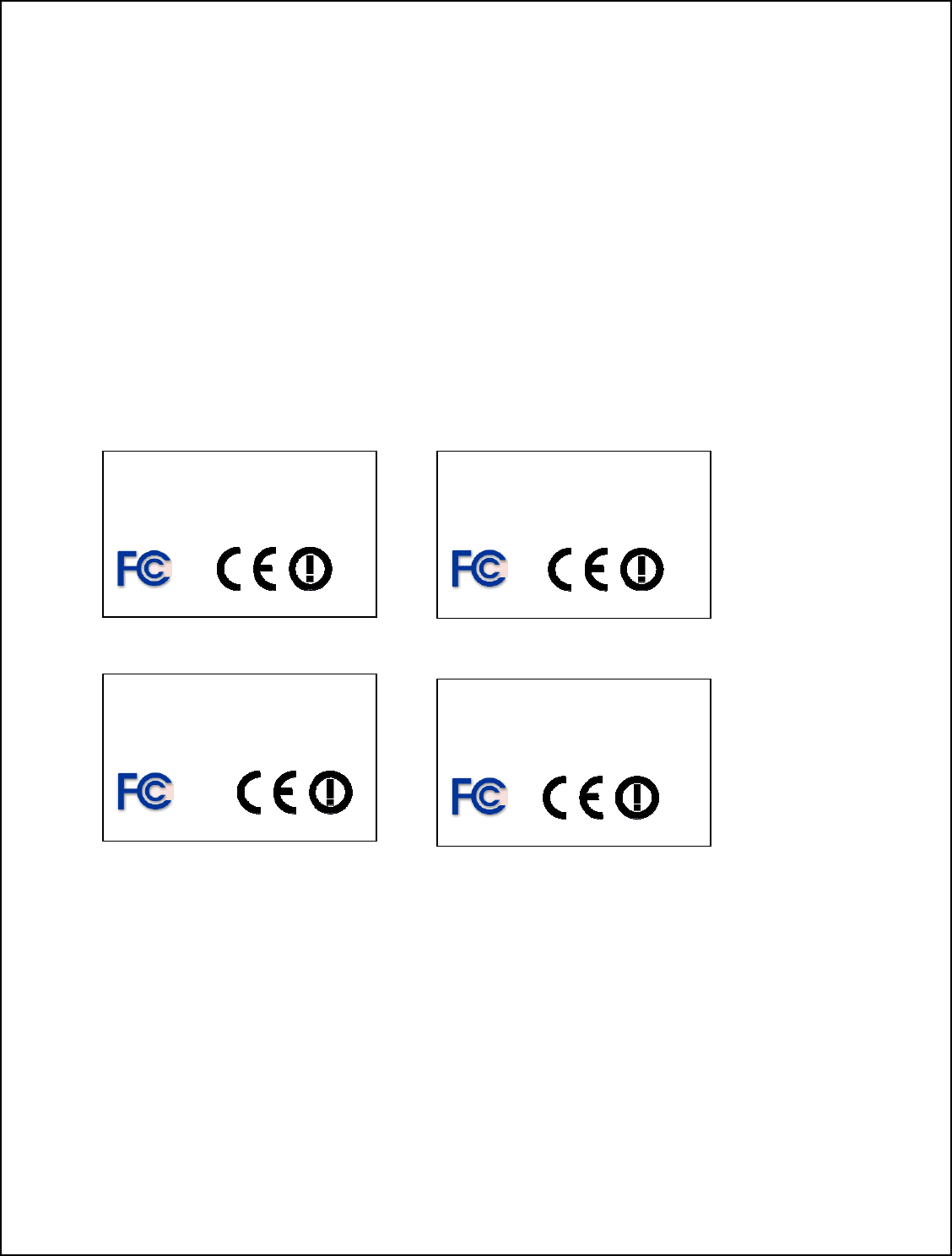
FCC, IC, and CE Label Location and Module Model
ion
WiFiHU2 m
iHU he modules are labeled with the appropriate WiFiHU2
ber and FCC Part 15 ID, IC registration number and CE mark. The
l ca n top of the metal shielding on the WiFiHU2 Module.
Identificat
The odule family is FCC Part 15 and IC (Industry Canada) certified. The
WiF 2 is also CE marked. T
module model num
labe n be found o
Ra odic m Research Inc.
FCC ID:
2377A- WIFIHU2
Radicom Research Inc.
IC: 2377A- WIFIHU2
Model: WiFiHU2-a
K7T-WIFIHU2 Model: WiFiHU2-c
FCC ID: K7T- WIFIHU2
IC:
R
Madicom Research Inc.
odel: WiFiHU2-a-1-NE
FCC ID: K7T- WIFIHU2
IC: 2377A- WIFIHU2
Radicom Research Inc.
Model: WiFiHU2-c-1-NE
FCC ID: K7T- WIFIHU2
IC: 2377A- WIFIHU2
12

Important Regulatory Compliance and User Information
re
formation. To maintain compliance in the finished product, carefully follow guidelines
only for OEM int ing conditions:
1) The antenna must be installed such that 20 cm is maintained between the
antenna and users. For laptop installations, the antenna m st be installed to ensure that
the proper spacing is maintained in the event the users places the device in their lap
uring use.
ule may not be co-located with any other transmitter or
nditions ab r
The final product with the modules installed needs to be tested for FCC Part 15, IC
(Industry Canada) CE, EMI/RFI compliance. Radicom certification documentation will
elp streamline the final product approval process. Contact Radicom for moh
in
in this section.
This device is intended egrators under the follow
u
d
2) The transmitter mod
antenna. As long as the two co ove are met, further transmitte testing will not
EM integrato ng their end product
liance requiremen dule installed (for
exam issions, PC pe , etc).
PORTANT NOTE: In the event that these conditions can not be met
be required. However, the O r is still responsible for testi
for any additional co
ple, digital device em
mp ts required with the mo
ripheral requirements
IM (for example
ertain laptop configurations or co-location with another transmitter), then the FCC
uthorization is no longer considered valid and the FCC ID can not
c
a be used on the final
roduct. In these circumstances, the OEM integrator will be responsible for re-evaluating
e end product (including the transmitter) and obtaining a separate FCC authorization.
p
th
13
Host (End Product) Labeling Requirements
To maintain compliance, the end product hosting the WiFiHU2 module must be properly
labeled to identify that this module is installed. This transmitter module is authorized
only when used in devices where the antenna is installed such that 20 cm is maintained
etween the antenna and users. The final end prod ct must have a label located in a
isible area with the following information:
ble and intact on the
evice in all normal conditions of use throughout the device’s expected lifetime. These
quirements may be met either by a separate label or nameplate permanently attached to
e device or by permanently imprinting or impressing the label directly onto the device.
perating instructions for satisfying RF Exposure compliance. The end user should NOT
e provided any instructions on how to remove or install the device. The users manual for
nd users must include the following information in a prominent location.
b u
v
Contains Transmitter
Module
Model: XXXXXXX
FCC ID: K7T- WIFIHU2
IC: 2377A- WIFIHU2
The XXXXXXX reflects the correct model installed into the host equipment: The
models are WiFiHU2-a, WiFiHU2-c, WiFiHU2-a-1-NE, or WiFiHU2-c-1-NE
The label shall be securely affixed to a permanently attached part of the device, in a
location where it is visible or easily accessible to the user, and shall not be readily
detachable. The label shall be sufficiently durable to remain fully legi
d
re
th
The label text shall be legible without the aid of magnification, but is not required to be
larger than 8-point font size.
End User Information: This equipment complies with FCC radiation exposure
imits set forth for an uncontrolled environment. End users must follow the specific l
o
b
e
14
FCC RF Radiation Exposure Statement
IMPORTANT NOTE: To comply with the FCC RF exposure compliance requirements,
the antenna used on this transmitter must be installed to provide a separation of at least 20 cm
from all persons and must not be co-located or operating in conjunction with any antenna or
transmitter. This device contains a low power transmitter. When this device is operational, use
only with the supplied, or recommended antenna. Unauthorized antenna, modification, or
attachments could damage the transmitter and may violate FCC regulations. Changes or
modifications not expressly approved by the manufacturer or party responsible for compliance
could void the user’s authority to operate the equipment.
FCC Interference Statement
This device complies with Part 15 of the FCC Rules. Operation is subject to the following
conditions:
(1) This device may not cause harmful interference
(2) This device must accept any interference received, including interference
that may cause undesired operation.
This equipment has been tested and found to comply with the limits for a Class B digital
device, pursuant to Part 15 of the F igned to provide reasonable CC Rules. These limits are des
protection against harmful interference in a residential installation.
This equipment generates and radiat uency energy and, if not installed and es radio freq
used in accordance with the instr ful interference to radio uctions, may cause harm
communications. There is no gua ill not occur in a particular installation. rantee that interference w
If this equipment does cause harm io or television reception, which can be ful interference to rad
determined by turning the equipment off and on, the user is encouraged to try to correct the
interference by one of the following measures:
● Reorient or relocate the receiving antenna.
● Increase the separation between the equipment and receiver.
● Connect the equipment into an outlet on a circuit different from that to which the receiver is
connected.
● Consult the dealer or an experienced radio/TV technician for assistance.
IC (Industry Canada) Statement
This product meets the applicable Industry Canada technical specifications. / Le present materiel
est conforme aux specifications techniques applicables d’Industrie Canada.
Europe – R&TTE Compliance Statement:
Hereby, Radicom Research Inc., declares that this equipment complies with the essential
requirements and other relevant provisions of DIRECTIVE 1999/5/CE OF THE
EUROPEAN PARLIAMENT AND THE COUNCIL of March 9, 1999 on radio
equipment and telecommunication terminal Equipment and the mutual recognition of
their conformity (R&TTE).
15

CE Declaration of Conformity
For the following equipment:
Radicom Research Inc. WiFi USB Modem Module
Model(s): WiFiHU2-a, WiFiHU2-c, WiFiHU2-a-1-NE, WiFiHU2-c-1-NE
is herewith confirmed to comply with the requirements set out in the Council
(European parliament) Directive on the Approximation of the
to Electromagnetic Compatibility of Radio and Telecom
Laws of the
EN 610
N 301 1 489-17 V2.1.1
EN 609
Member States relating
device (1999/5/CE). For the evaluation regarding this Directive, the following
standards were applied:
00-3-2:2006+A2:2009, EN 300 328 V1.7.1
489-1, V1.8.1, EN 61000-3-3:2008, EN 30
, EN 62311: 2008,
E
50-1:2006+A11:2009+A1: 2010+A12:2011
________________________
This equipment is marked with the and can be used throughout the
European community.
France – 2.4GHz for Metropolitan France:
In all Metropolitan departments, wireless LAN frequencies can be used under the
following conditions, either for public or private use:
e 2400-2483.5
MHz frequency
3 MHz band
his
• Indoor use: maximum power (EIRP*) of 100 mW for the entir
band
• Outdoor use: maximum power (EIRP*) of 100 mW for the 2400-2454 MHz band
and with maximum power (EIRP*) of 10 mW for the 2454-248
Caution: Exposure to Radio Frequency Radiation.
To comply with RF exposure compliance requirements, for mobile configurations, a
separation distance of at least 20 cm must be maintained between the antenna of t
device and all persons.
16
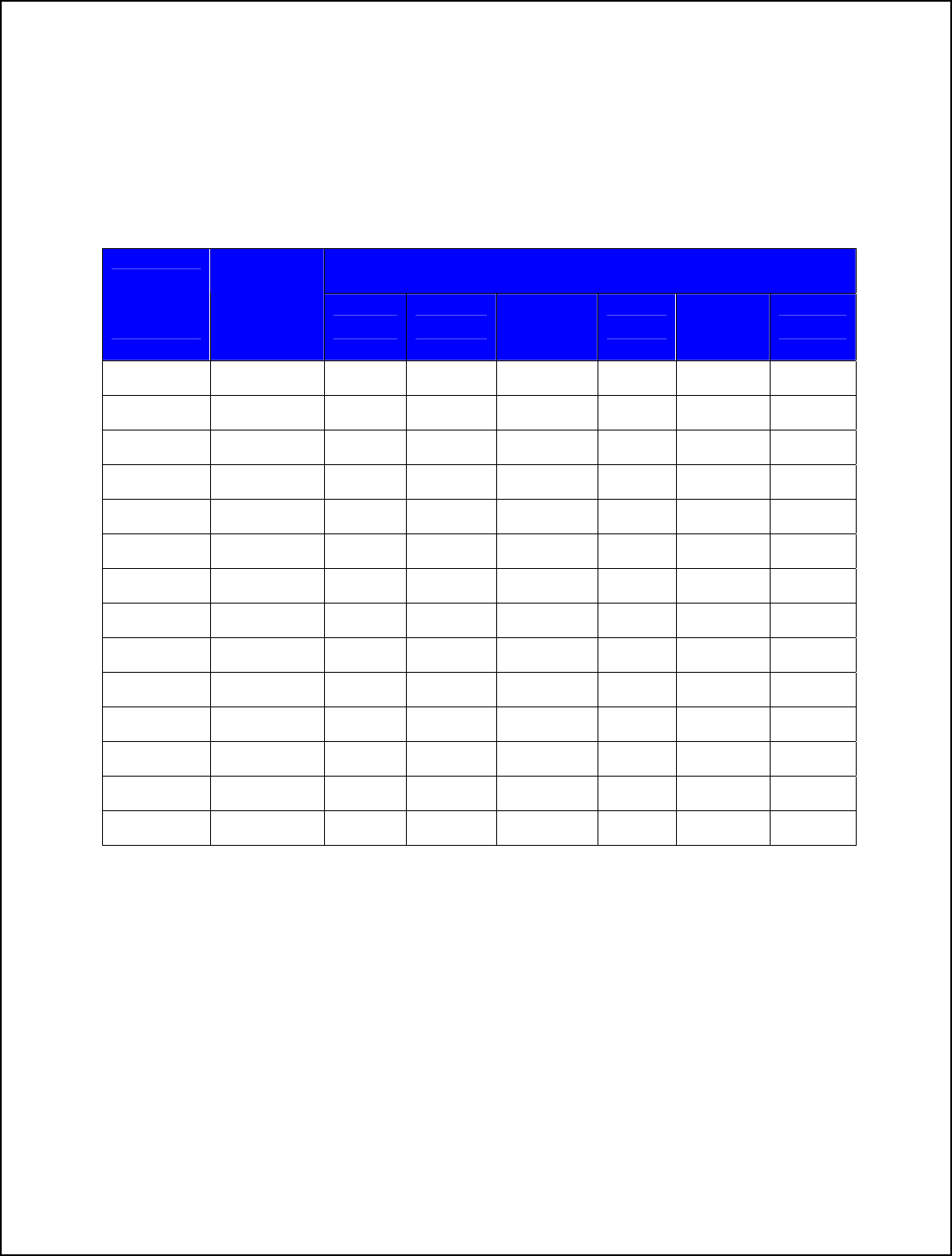
WiFiHU2 Regulatory Domain Frequencies
e ch nel identifiers, channel center frequencies, and regulatory domains of each 22-
Th an
MHz-wide channel are shown in following table.
Regulatory Domains
Model:
WiFiHU2
Family
Frequency
(MHZ) Japan ETSI North
America Israel France
Outdoor Mexico
1 2412
∨ ∨ ∨ ∨
2 2417
∨ ∨ ∨ ∨
3 2422
∨ ∨ ∨ ∨ ∨
4 2427
∨ ∨ ∨ ∨ ∨
5 2432
∨ ∨ ∨ ∨ ∨
6 2437
∨ ∨ ∨ ∨ ∨
7 2442
∨ ∨ ∨ ∨ ∨
8 2447
∨ ∨ ∨ ∨ ∨
9 2452
∨ ∨ ∨ ∨ ∨
10 2457
∨ ∨ ∨ ∨
11 2462
∨ ∨ ∨ ∨
12
2467
∨ ∨
13 2472
∨ ∨
14 2484
∨
17
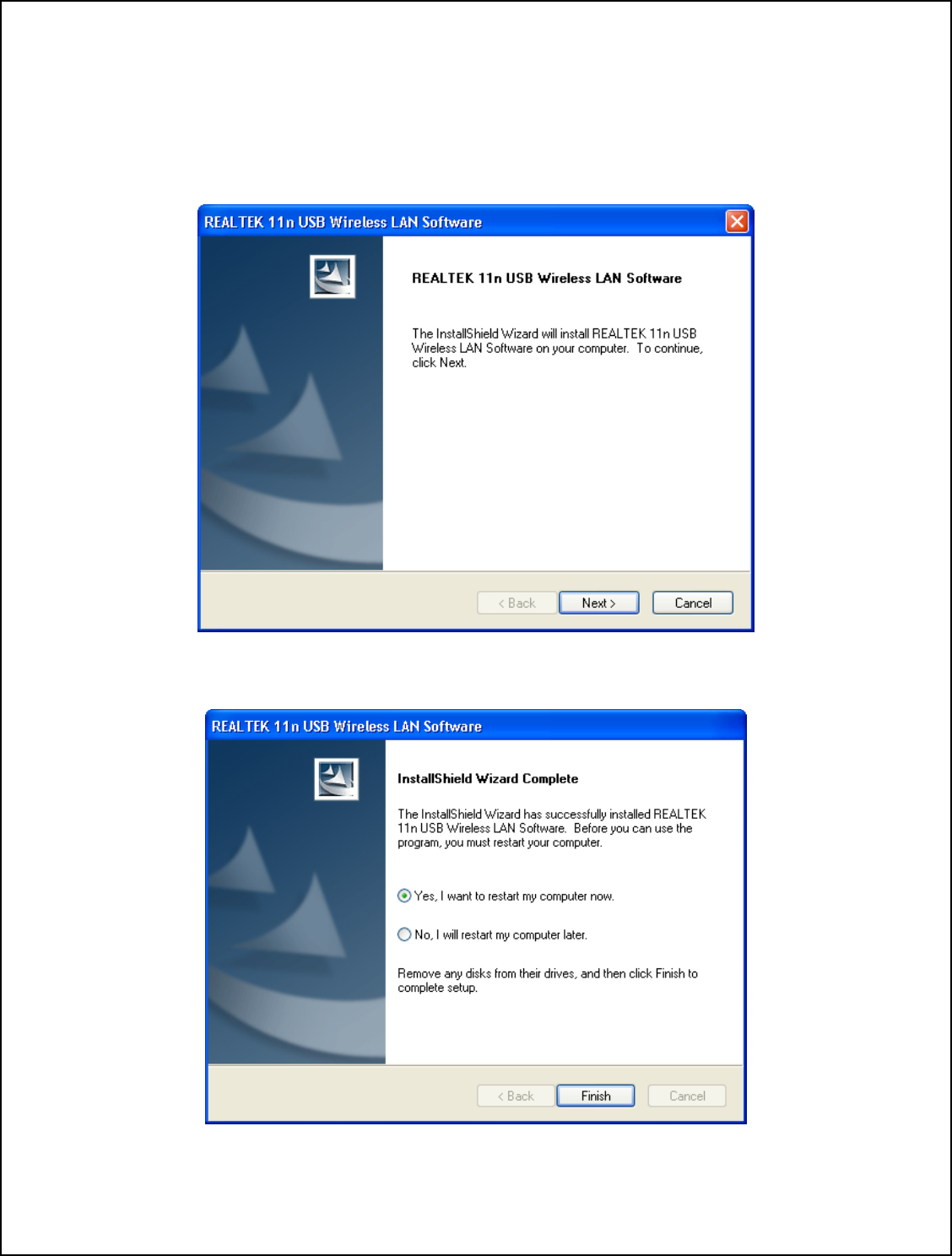
Driver Installation Guide For Windows XP
Do not plug the WiFiHU2 module into USB port until the drivers are loaded.
e WiFiHU2 Drivers + Manual Folder.
pen the WiFiHU2 Driver Folder. Open the Windows folder and select “Setup.exe”.
Insert the installation disc into CD-ROM. Open th
O
Click Next. Windows will now install the driver. This may take a few moments.
Click Finish.
18
Windows will to a USB
ort. Windows will briefly display “Found New Hardware” and autom
now restart. After the computer reboots, plug the WiFiHU2 in
atically load the p
drivers.
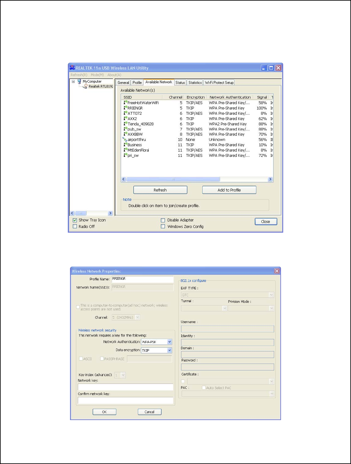
Left Click the 5 red signal strength bars of the Realtek Icon in the Window system tray.
The “Realtek Wireless LAN Utility” box will be displayed.
Left Click the “Available Network” box. Highlight and Double Click the network
ant to connect with. The “Wireless Network Property” box will appear.
you
w
E
19
nter and then confirm the Network Key, then Click OK.
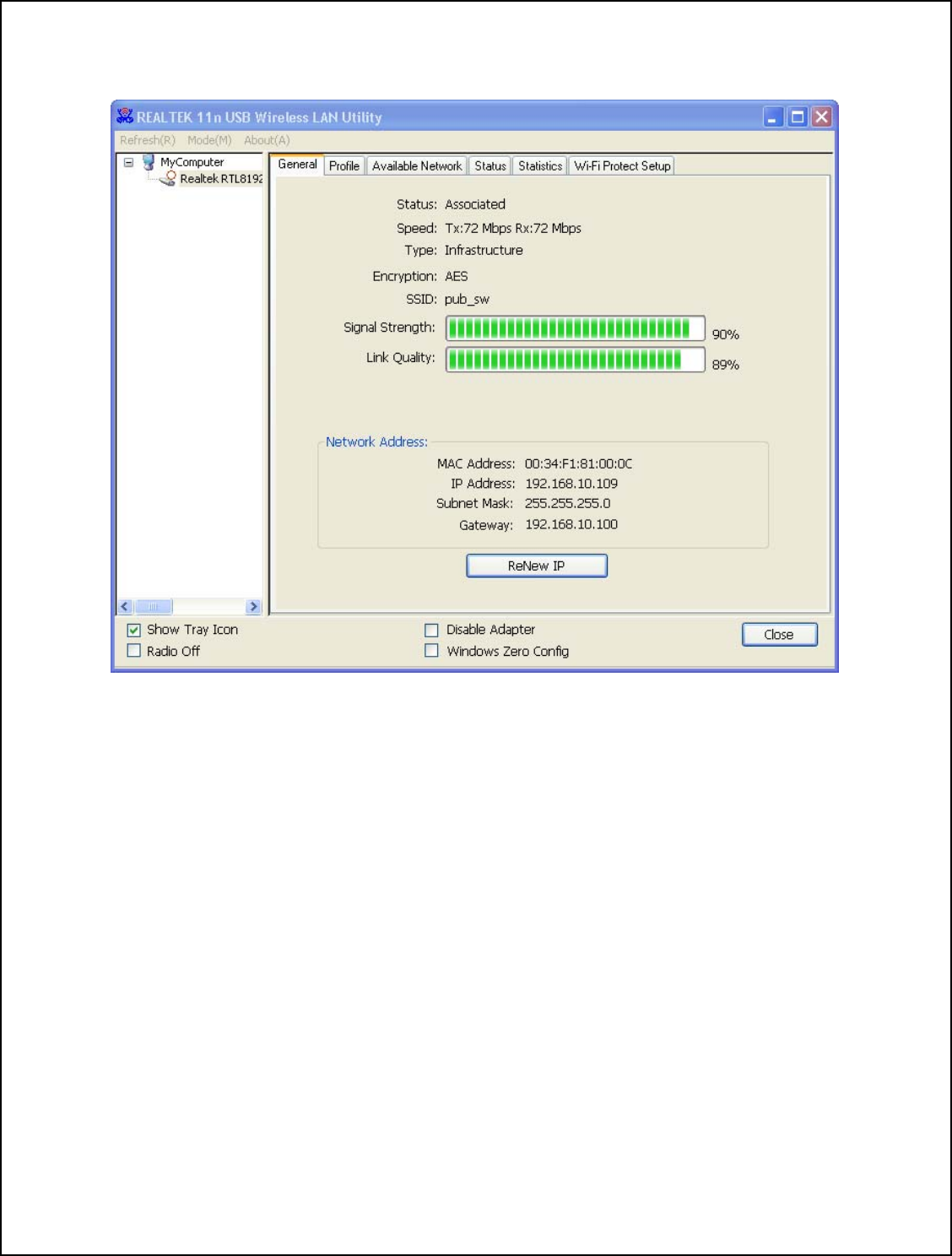
The “LAN Utility” box will display the Signal Strength and Link Quality.
The WiFiHU2 is now connected to the network. The signal strenghth bars in the Realtek
Icon in the system tray should be green.
WiFiHU2 USB Linux Driver Quick Installation Guide
Software Package & Platform requirements:
• The software package contains one WiFiHU2 Linux driver (source code) that
supports Linux Kernel version 2.6.18 thru 2.6.38 and Kernel version 3.0.2, and
WiFiHU2 documents.
• Platform requirements: PC-based Linux platform (i386) and WiFiHU2 Linux
driver.
NOTE: Kernel versions 2.6.41 and 3.2.1 will automatically detect the WiFiHU2.
20

Limited Warranty
Warranty Coverage and Duration
Radicom Research, Inc. (“RRI”) warrants to the original purchaser its RRI-manufactured
products (“Product”) against defects in material and workmanship under normal use and
service for a period of one year from the date of delivery. During the applicable warranty
period, at no charge, RRI will, at its option, either repair, replace or refund the purchase
price of this Product, provided it is returned in accordance with the terms of this warranty
to RRI. Repair, at the option of RRI, may include the replacement of parts, boards or
other components with functionally equivalent reconditioned or new parts, boards or
other components. Replaced parts, boards or other components are warranted for the
balance of the original applicable warranty period. All replaced items shall become the
property of RRI.
RRI MAKES NO GUARANTEE OR WARRANTY THAT THE PRODUCT WILL
REVENT OCCURRENCES, OR THE CONSEQUENCES THEREOF, WHICH THE
RODUCT IS DESIGNED TO DETECT.
to any other party. This is the complete
anufactured by RRI, and RRI assumes no obligation or
or additions or modifications to this warranty. In no case does RRI warrant the
installation, maintenance or service of the Product.
by RRI that
attached to or used in connection with the Product, or for operation of the Product with
ent is expressly excluded from this
war n
which m I
assume coverage or suitability of the Product for any particular
application. Buyer acknowledges that RRI does not know a particular purpose for which
buyer wants the Product, and that buyer is not relying on RRI’s skill and judgment to
sele
P
P
This expressed limited warranty is extended by RRI to the original end-user purchaser
only, and is not assignable or transferable
warranty for the Product m
liability f
RRI is not responsible in any way for any ancillary equipment not furnished
is
any ancillary equipment, and all such equipm
ra ty. Because of wide variations in topographical and atmospheric conditions,
ay require availability of repeater stations or of particular radio frequencies, RR
s no liability for range,
ct or furnish suitable goods.
21

What this Warranty does NOT Cover:
) Defects or damage resulting from use of the Product in other than its normal and
customary manner.
) Defects or damage from misuse, accident or neglect.
(c) Defects of damage from improper testing, operation, maintenance, installation,
alteration, modification or adjustm
) Disassembly or repair of the Product in such a manner as to adversely affect
nspection and testing to verify any warranty claim.
) Any Product that has had its serial number or date code removed or made illegible.
(a
(b
ent.
(d
performance or prevent adequate i
(e
How to Receive Warranty Service:
To obtain warranty service, contact RRI by phone (408) 383 9006 for RMA Department
or email to rma@radi.com for an RMA (Return Merchandise Authorization) number.
Deliver or send the Product, transportation and insurance prepaid to RRI, with the RMA
number clearly marked on the outside of the package.
General Provision
his warranty setT s forth the full extent of RRI’s responsibilities regarding the Product.
E
NIENCE, COMMERCIAL LOSS,
Repair, replacement or refund of the purchase price, at RRI’s option, is the exclusive
remedy.
HIS WARRANTY IS GIVEN IN LIEU OF ALL OTHER EXPRESSED T
WARRANTIES. ANY APPLICABLE IMPLIED WARRANTIES, INCLUDING
WITHOUT LIMITATION THE IMPLIED WARRANTY OF MERCHANTABILITY,
ARE LIMITED TO THE DURATION OF THIS LIMITED WARRANTY. TO TH
FULLEST EXTENT PERMITTED BY LAW, RRI DISCLAIMS ANY LIABILITY
FOR DAMAGES IN EXCESS OF THE PURCHASE PRICE OF THE PRODUCT, FOR
NY LOSS OF USE, LOSS OF TIME, INCONVEA
LOST PROFITS OR SAVING OR OTHER INCIDENTAL, SPECIAL OR
CONSEQUENTIAL DAMAGES ARISING OUT OF THE USE OR INABILITY TO
USE OR FAILURE OF SUCH PRODUCT.
22

earch
Contacting Radicom Res
If more information or technical support is needed, please contact us:
2148 Bering Drive
San Jose, CA. 95131
Telephone: (408) 383 9006
Fax: (408) 383 9007
or
e-mail: sales@radi.com
http://www.radi.com/
23

Warning
Federal Communications Commission Statement Warning
Warning: Changes or modifications to this unit not expressly approved by the party responsible for compliance could void the
user authority to operate the equipment.
“This device complies with Part 15 of the FCC Rules. Operation is subject to the following
two conditions: (1) this device may not cause harmful interference, and (2) this device must accept any interference received,
including interference that may cause undesired operation.”
This device is intended only for OEM integrators under the following conditions:
1) The antenna must be installed such that 20 cm is maintained between the antenna and users. For laptop installations, the
antenna must be installed to ensure that the proper spacing is maintained in the event the users places the device in their
lap
during use (i.e. positioning of antennas must be placed in the upper portion of the LCD panel only to ensure 20 cm will be
maintained if the user places the device in their lap for use) and
2) The transmitter module may not be co-located with any other transmitter or antenna.
As long as the 2 conditions above are met, further transmitter testing will not be required. However, the OEM integrator
is still responsible for testing their end-product for any additional compliance requirements required with this module
installed (for example, digital device emissions, PC peripheral requirements, etc.).
IMPORTANT NOTE: In the event that these conditions can not be met (for example certain laptop configurations or
co-location with another transmitter), then the FCC authorization is no longer considered valid and the FCC ID can not be
used on the final product. In these circumstances, the OEM integrator will be responsible for re-evaluating the end product
(including the transmitter) and obtaining a separate FCC authorization.
End Product Labeling
This transmitter module is authorized only for use in devices where the antenna may be installed such that 20 cm may be
maintained between the antenna and users (for example access points, routers, wireless ASDL modems, certain laptop
configurations, and similar equipment). The final end product must be labeled in a visible area with the following: "Contains
TX FCC ID: K7T-WIFIHU2".
RF Exposure Manual Information That Must be Included
The users manual for end users must include the following information in a prominent location "IMPORTANT NOTE: To
comply with FCC RF exposure compliance requirements, the antenna used for this transmitter must be installed to provide a
separation distance of at least 20 cm from all persons and must not be co-located or operating in conjunction with any other
antenna or transmitter." Additional Information That Must be Provided to OEM Integrators
The end user should NOT be provided any instructions on how to remove or install the device.
Industry Canada Interference Statement Warning
“This device complies with Industry Canada licence-exempt RSS standard(s). Operation is subject to the following two
conditions: (1) this device may not cause interference, and (2) this device must accept any interference, including
interference that may cause undesired operation of the device.”
Le présent appareil est conforme aux CNR d'Industrie Canada applicables aux appareils radio exempts de licence.
L'exploitation est autorisée aux deux conditions suivantes : (1) l'appareil ne doit pas produire de brouillage, et (2) l'utilisateur
de l'appareil doit accepter tout brouillage radioélectrique subi, même si le brouillage est susceptible d'en compromettre le
fonctionnement.