Radio Active Design UV-1GBS UV-1G Base Station User Manual TITLE GOES HERE
Radio Active Design, LLC UV-1G Base Station TITLE GOES HERE
User Manual
UV-1G
WIRELESS INTERCOM SYSTEM
User Manual
2
3
• Per FCC 15.19(a)(3) and (a)(4): This device complies with part 15 of the FCC
Rules. Operation is subject to the following two conditions: (1) This device may
not cause harmful interference, and (2) this device must accept any interference
received, including interference that may cause undesired operation.
• Per FCC 15.21: Changes or modifications not expressly approved by Radio
Active Designs could void the user's authority to operate the equipment.

4
Table of Contents
Table of Contents..................................................................................................................4
General Information ..........................................................................................................6
Features ............................................................................................................................6
Terminology ......................................................................................................................6
UV-1G Specifications ............................................................................................................7
Transmitter .......................................................................................................................7
Receiver ............................................................................................................................8
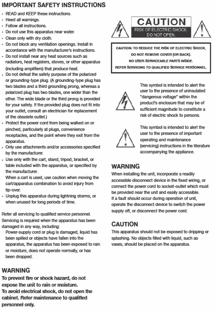
System Diagram.................................................................................................................9
Base Station ........................................................................................................................10
Front Panel Button Descriptions ......................................................................................10
Front Panel LED Description ............................................................................................12
Rear Panel Description ....................................................................................................13
Belt Pack ..........................................................................................................................14
Quick Start Guide ................................................................................................................16
Base Station Operation ....................................................................................................16
Belt Pack ..........................................................................................................................16
Base Station Operation .......................................................................................................17
Power ..............................................................................................................................17
Powering Up ................................................................................................................17
Powering Down ...........................................................................................................17
Home Screen ...................................................................................................................18
Transmitter Power Level ..................................................................................................18
Receiver Status ................................................................................................................18
Base Station Link Mode ...................................................................................................18
Local Headset Status........................................................................................................19
RSSI Screen ......................................................................................................................19
Menu Structure...................................................................................................................20
Passcode Protection ........................................................................................................20
Receiver Settings .............................................................................................................20
Transmitter Settings ........................................................................................................21
Local Headset Options .....................................................................................................22
Display Settings ..................................................................................................................23
Blackout Mode ................................................................................................................23
Backlight Time .................................................................................................................24
LCD Brightness.................................................................................................................25
LCD Contrast ....................................................................................................................25
LED Brightness .................................................................................................................26
Base Station Link Modes .....................................................................................................26
Info Screen ......................................................................................................................27
Enabling/Disabling the Passcode .....................................................................................27
Changing the Passcode Combine Passcode Sections? ......................................................28
5
Gain Adjustments ...............................................................................................................29
Intercom 1 & 2 ................................................................................................................29
Auxiliary ..........................................................................................................................29
Stage Announce ..............................................................................................................30
Local Headset ..................................................................................................................30
Microphone Gain .............................................................................................................30
Volume ............................................................................................................................30
Intercom CH1 and CH2 Buttons and LEDs ........................................................................31
Talk Button ......................................................................................................................31
Belt Pack Operation ............................................................................................................31
Battery ............................................................................................................................32
Powering Up ....................................................................................................................32
Powering Down ...............................................................................................................32
Home Screen ...................................................................................................................33
Talk Buttons and LEDs..................................................................................................33
Intercom and Programmable Button Labels .................................................................33
Signal and Battery Meters ...........................................................................................33
Local Headset Volume..................................................................................................33
Power / Menu Button ......................................................................................................34
Menu Structure...................................................................................................................34
Display Settings ...............................................................................................................34
Blackout Mode ................................................................................................................34
Backlight Time .................................................................................................................35
LCD Brightness.................................................................................................................35
LCD Contrast ....................................................................................................................36
LED Brightness .................................................................................................................36
Advanced Settings ..............................................................................................................36
Passcode Protection ........................................................................................................37
Transmitter Settings ........................................................................................................37
Receiver Settings .............................................................................................................39
Channel Labels ................................................................................................................40
Soft Button Labels ...........................................................................................................42
Rx Volume Options ..........................................................................................................43
Headset Options ..............................................................................................................44
Info Screen ......................................................................................................................45
Enabling/Disabling the Passcode .....................................................................................45
Changing the Passcode ....................................................................................................45
Microphone Gain .............................................................................................................46

6
General Information
The Radio Active Designs® UV-1G is a two-channel full-duplex UHF/VHF wireless intercom
system that incorporates up to six wireless belt pack units per base station. Each belt pack is
capable of simultaneous Talk and Listen on two separate audio channels. Additionally, belt
packs have Stage Announce and two-channel Wireless Talk-Around functionality.
The wired interface supports 2W Audiocom® (Telex), RTS® TW, and Clear-Com® varieties.
Support for 4W systems is present through RJ-11 compatible jacks.
Features
• Excellent RF noise immunity through revolutionary design
• Full duplex operation incorporates UHF transmitters and VHF receivers
• Support for up to six Belt Pack units in one Base Station
• Multiple Base Station support when more than six belt packs are linked
• Two wireless intercom channels
• Programmability via PC interface or User Interface in the field
• Internal antenna in the Belt Pack
• Very low occupied bandwidth
• Frequency Response: 100Hz to 8kHz
• Audio Dynamic Range ≥ 50dB
• AES-48 Compliant
Terminology
• LCD – Liquid Crystal Display
• LED – Light Emitting Diode
• WTA – Wireless Talk-Around
• SA – Stage Announce
• 4W – 4-Wire
• 2W – 2-Wire
• VHF – Very High Frequency
• UHF – Ultra High Frequency
• IEC – International Electrotechnical Commission
• FCC – Federal Communications Commission
• RSSI – Received Signal Strength Indicator
• FSTN – Film compensated / Formulated / Filtered Super-twisted Nematic

7
UV-1G Specifications
RF Frequency Range 470-608 and 614-98MHz Base Tx, 174-216MHz Belt Tx
Power Requirements 100-240 VAC, 50-60 Hz, 2.5A max IEC receptacle
Temperature Range -4º F to 131º F (-20º C to 55º C)
Dimensions
Base Station 14.68” x 17” x 1.75”
Belt Pack 5.55” x 3.78” x 1.83”
Weight
Base Station 7 lbs.
Belt Pack 14 Oz
TX Antenna
Belt Pack Internal
Base Station 5/8 wave (Supplied)
RX Antenna
Belt Pack Internal
Base Station 1/4 wave (Supplied)
FCC ID 2AA6F-UV-1GBP, 2AA6F-UV-1GBS
IC ID 11482A-UV1GBP, 11482A-UV1GBS
Frequency Response 100Hz-8 kHz
Four Wire Input Level Adjustable (2Vrms typical)
Four Wire Output Level Adjustable (2Vrms typical)
Auxiliary Input Adjustable (2Vrms typical)
Auxiliary Output Adjustable (2Vrms typical into 600Ω)
Stage Announce Output Internally Adjustable (2Vrms typical at rated deviation into
600Ω)
Stage Announce Relay Dry Contact, rated at 1 Amp, 24V Max
Mic input sensitivity 9mV
Local Headset Output 40mW output into 600Ω (1% Distortion)
Transmitter
Type Two Transmitters, Synthesized
Transmit Power (each transmitter) 100mW, 250mW PEP Max (High Part 74 use only),
10mW, 20mW, 50mW (Part 15 use)
Modulation Type ENB
RF Frequency Stability ±1.5ppm
Occupied Bandwidth 25kHz
Radiated Harmonics and Spurious Exceeds FCC Specifications

8
Receiver
Type Direct Conversion
RF Sensitivity -117dBm for 12dB SINAD
Squelch Threshold Automatic
IF Selectivity 25kHz
RF Frequency Stability ±1.5 ppm
Distortion <1% at full modulation
9
System Diagram
10
Base Station
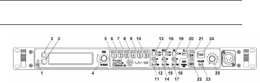
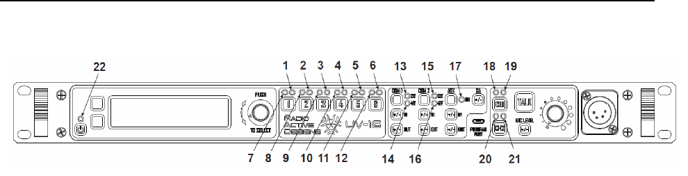
Front Panel Button Descriptions
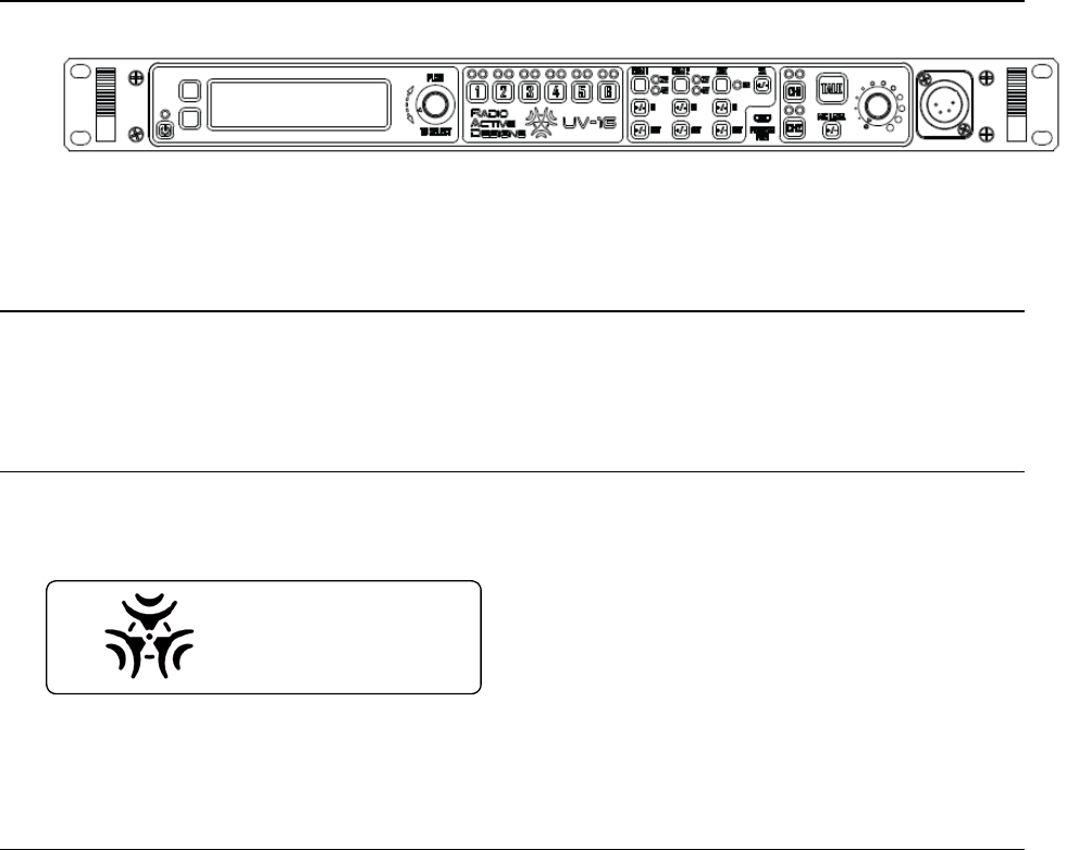
Figure 1 UV-1G Front Panel Buttons
1. Power Button: Momentary press to power up unit; press and hold to power off.
2. Soft Key 1: Menu Navigation; variable button function.
3. Soft Key 2: Menu Navigation; variable button function.
4. Rotary Encoder and Select: Rotate for Menu Navigation; press to make selection of a
given menu option.
5. Channel 1 Mute/Unmute: Momentary press to Mute or Unmute Belt Pack #1.
6. Channel 2 Mute/Unmute: Momentary press to Mute or Unmute Belt Pack #2.
7. Channel 3 Mute/Unmute: Momentary press to Mute or Unmute Belt Pack #3.
8. Channel 4 Mute/Unmute: Momentary press to Mute or Unmute Belt Pack #4.
9. Channel 5 Mute/Unmute: Momentary press to Mute or Unmute Belt Pack #5.
10. Channel 6 Mute/Unmute: Momentary press to Mute or Unmute Belt Pack #6.
11. Intercom 1 Output Gain: Momentary press to show Intercom 1 Output Gain screen on
LCD; press and hold to force this screen to persist. See Gain Adjustments section.
12. Intercom 1 Input Gain: Momentary press to show Intercom 1 Input Gain screen on LCD;
press and hold to force this screen to persist. See Gain Adjustments section.
13. Intercom 1 Select: Momentary press toggles Intercom 1 between one of three options:
2-wire, 4-wire, Off.
14. Intercom 2 Output Gain: Momentary press to show Intercom 2 Output Gain screen on
LCD; press and hold to force this screen to persist. See Gain Adjustments section.
15. Intercom 2 Input Gain: Momentary press to show Intercom 2 Input Gain screen on LCD;
press and hold to force this screen to persist. See Gain Adjustments section.
16. Intercom 2 Select: Momentary press toggles Intercom 2 state between one of three
options: 2-wire, 4-wire, off.
17. Auxiliary Output Gain: Momentary press to show Auxiliary Output Gain screen on LCD;
press and hold to force this screen to persist. See Gain Adjustments section.
18. Auxiliary Input Gain: Momentary press to show Auxiliary Input Gain screen on LCD;
press and hold to force this screen to persist. See Gain Adjustments section.
19. Auxiliary Enable/Disable: Momentary press enables or disables Auxiliary Input and
Output.
20. Stage Announce Gain: Momentary press to show Stage Announce Gain screen on LCD;
press and hold to force this screen to persist. See Gain Adjustments section.
11
21. Channel 1 Enable/Disable: Momentary press toggles state of transmitter for local
headset respecting Channel 1.
22. Channel 2 Enable/Disable: momentary press toggles state of transmitter for local
headset respecting Channel 2.
23. Headset Microphone Gain: Momentary press to show Headset Microphone Gain screen
on LCD; press and hold to force this screen to persist. See Gain Adjustments section.
24. Talk Button: Momentary press latches local headset talk on channels determined by the
status of 21 and 22. Press and hold for non-latching operation.
25. Headset Volume: Headset volume audio potentiometer.
12
Front Panel LED Description
Figure 2 Front Panel LED Descriptions
1-6. Channel n Status LED: Green = receiver signal present, flashing Red = belt pack battery
low, alternating Green/Red = receiver signal present and belt pack battery low.
7-12. Channel n Mute LED: Green = channel enabled, Yellow = channel muted, Off = channel
disabled.
13. Intercom 1 2-Wire Enable LED: green = enabled, red = over modulation, off = disabled.
14. Intercom 1 4-Wire Enable LED: green = enabled, red = over modulation, off = disabled.
15. Intercom 2 2-Wire Enable LED: green = enabled, red = over modulation, off = disabled.
16. Intercom 2 4-Wire Enable LED: green = enabled, red = over modulation, off = disabled.
17. Auxiliary Enable LED: green = enabled, red = over modulation, off = disabled.
18. Local Headset Channel 1 Enable LED: green = enabled, off = disabled.
19. Local Headset Channel 1 Status LED: green = local headset traffic on channel 1 (i.e. Talk
button being pressed and local headset channel 1 enabled), red = over modulation,
off = no traffic.
20. Local Headset Channel 2 Enable LED: green = enabled, off = disabled.
21. Local Headset Channel 2 Status LED: green = local headset traffic on channel 2 (i.e. Talk
button being pressed and local headset channel 2 enabled), red = over modulation,
off = no traffic.
22. Power / Fan Fail LED: green = system powered up, red = fan failure condition.
13
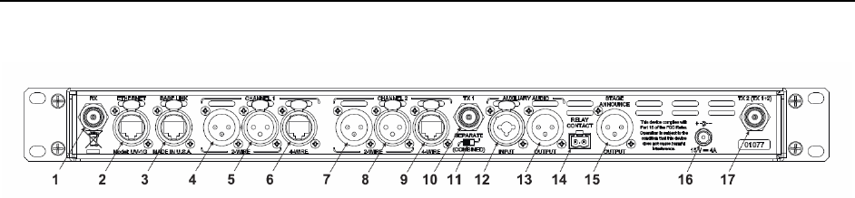
Rear Panel Description
Figure 3 Base Station Rear Panel
1. Receive antenna (TNC)
2. Ethernet RJ-45 Port
3. Base Link RJ-45 Port
4. Intercom 1 3-pin XLR Male
5. Intercom 1 3-pin XLR Female
6. Intercom 1 4-wire port
7. Intercom 2 3-pin XLR Male
8. Intercom 2 3-pin XLR Female
9. Intercom 2 4-wire port
10. Transmit Antenna 1 (TNC)
11. Transmit Antenna Selection Switch
12. Auxiliary XLR 3-pin with ¼” audio input
13. Auxiliary XLR 3-pin audio output
14. Stage Announce Relay Contact
15. Stage Announce XLR 3-pin audio output
16. DC Power Input
17. Transmit Antenna 2 (TNC)
14
Belt Pack
1
34
2
5
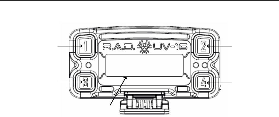
Figure 4 Belt Pack Top View
1. Channel 1 Button: at the home screen, push this button to transmit on Channel 1. In the
menu, this button is used to select the item that is boxed.
a. Talk / Over modulation LED for Channel 1: this LED turns on when the Channel 1
talk button is pressed. It is normally green while the transmitter is active for that
button, and it will turn red if over modulation occurs.
2. Channel 2 Button: at the home screen, push this button to transmit on Channel 2. In the
menu, this button is used to select the item that is boxed.
a. Talk / Over modulation LED for Channel 2: this LED turns on when the Channel 2
talk button is pressed. It is normally green while the transmitter is active for that
button, and it will turn red if over modulation occurs.
3. Soft Key 1 Button: at the home screen, push this button to transmit on the user-
configured channel (Channels 1+2, WTA 1, WTA 2, WTA 1+2, SA). In the menu, this is a
“soft key” and will perform the function that is described on the LCD.
a. Talk / Over modulation LED for the Programmable 1 talk button: this LED turns
on when the button is pressed. It is normally green while the transmitter is
active for that button, and it will turn red if over modulation occurs.
4. Soft Key 2 Button: at the home screen, push this button to transmit on the user-
configured channel (Channels 1+2, WTA 1, WTA 2, WTA 1+2, SA). In the menu, this is a
“soft key” and will perform the function that is described on the LCD.
a. Talk / Over modulation LED for the Programmable 2 talk button: this LED turns
on when the button is pressed. It is normally green while the transmitter is
active for that button, and it will turn red if over modulation occurs.
5. LCD with Backlight: The backlight turns on when a button is pressed as long as the belt
pack isn’t set up to blackout the backlight.
15
9
78
6
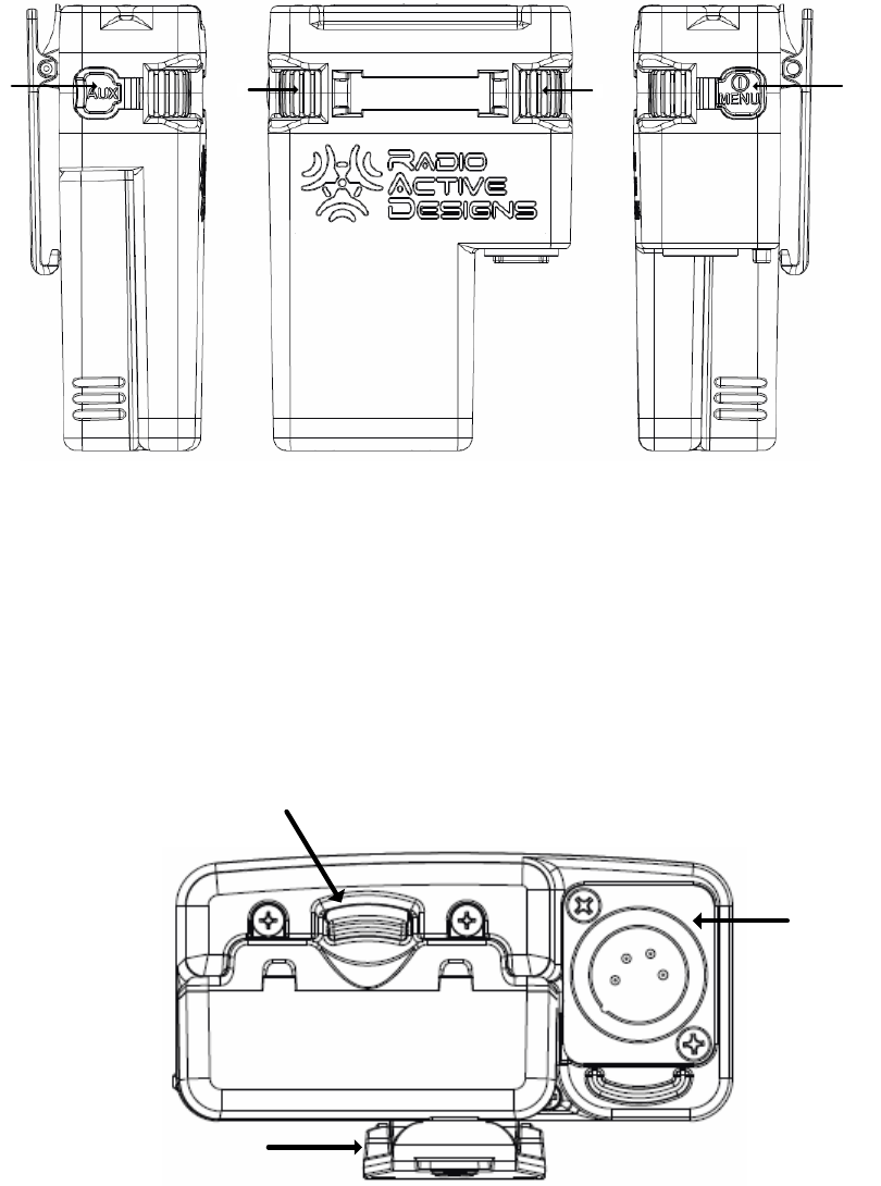
Figure 5 Belt Pack Side Views
6. Auxiliary Ports: USB port and auxiliary audio input.
7. Left Encoder: at the home screen, this adjusts the headset volume for Channel 1. In the
menu, it is used for navigation and changing values.
8. Right Encoder: at the home screen, this adjusts the headset volume for Channel 2. In
the menu, it is used for navigation and changing values.
9. Power / Menu Button: located on the side of the belt pack, a momentary press turns
the belt pack on; press and hold to turn the unit off. When the belt pack is on, a
momentary press will toggle the menu.
10
11
12
Figure 6 Belt Pack Bottom View
10. Headset connector: four pin (shown) or five pin XLR male.
11. Battery Latch.
12. Removable Belt Clip

16
Quick Start Guide
Base Station Operation
1. Power: Insert a standard 120VAC IEC power cable into the power connector located on
the back of the base station.
2. Antennas: Connect antennas to ports on back of Base Station.
3. Connect Headset: Insert the headset connector into the base station until it snaps into
place.
4. Powering Up: Press the power button. The display will turn on as well as various LEDs.
5. Tx & Rx Frequencies: Program the transmitter and receiver frequencies as desired. See
Section 6: Base Station Operation or Section 8: PC Application for information on how to
program frequencies from the Base Station itself or from the PC Application. Note: the
defaults for Rx 1 – Rx 6 are 175MHz, 176MHz, 177MHz, 178MHz, 179MHz, and 180MHz.
The default for Tx1 is 519MHz and Tx2 is 520MHz.
6. Intercom 2W / 4W:
Belt Pack
1. Batteries: Place five (5) new “AA” lithium or alkaline batteries into the provided battery
sled, in the correct polarity.
2. Connect Headset: Insert the headset connectors into the belt packs until they snap into
place.
3. Powering Up: Press the Power / Menu button that is located on the side of the belt
pack. The display will turn on and the belt pack will power on.
4. Tx & Rx Frequencies: Program the transmitter and receiver frequencies as desired. See
Section 7: Belt Pack Operation or Section 8: PC Application for information on how to
program frequencies from the Belt Pack itself or from the PC Application. Note: the
default for Rx1 is 519MHz, Rx2 is 520MHz, and Tx is 175MHz. These values will work
with the Base Station defaults for one belt pack (belt pack #1). The other belt packs will
need their frequencies changed from the defaults. See notes above.
Congratulations, your new base station is ready for use!
17
Base Station Operation
Figure 7 Base Station
Power
The Base Station is powered by 120VAC, 2.5A (max) using a standard IEC power cable to a
low voltage power supply.
Powering Up
To turn the Base Station on, press the POWER button as shown in Figure 7 above. While the
Base Station powers up, a splash screen will appear.
RADIO
ACTIVE
DESIGNS . . .
Once the Base Station is ready for use, the Home Screen will be displayed.
Powering Down
To turn the Base Station off, press and hold the POWER button until the LCD screen goes
blank.
18
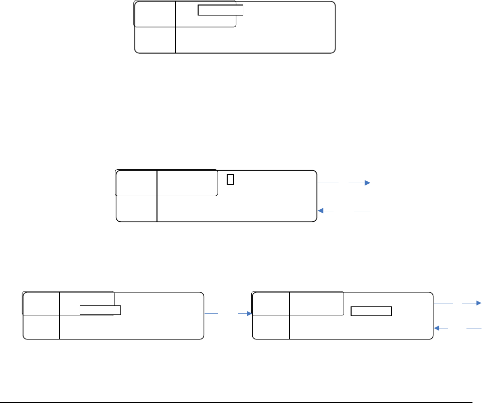
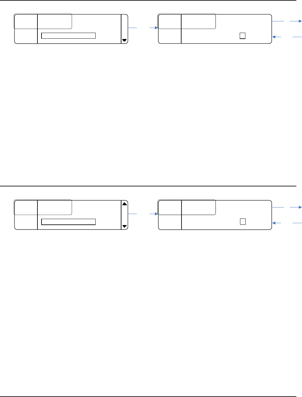
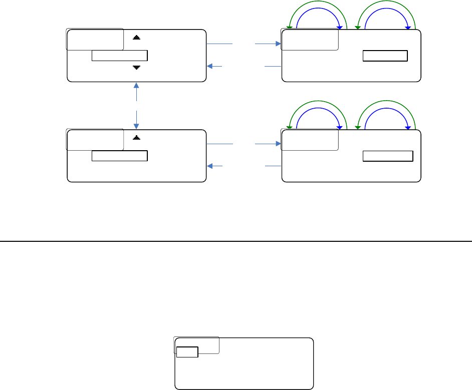
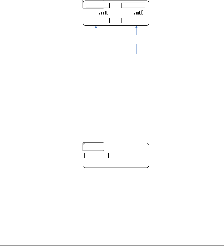
Home Screen
The Home Screen is the root of the UV-1G Base Station UI. It displays information regarding
transmitter power level, receiver status, base station link mode, and local headset status. The
left portion of the screen provides links to the main menu and RSSI screens.
MENU
MENU
....
....
M
M
.........
.........
R
R
1
1
C
C
1
1
...
...
R
R
4
4
OFF
OFF
MENU
MENU
....
....
T
T
1 50
1 50
mW
mW
...
...
R
R
2
2
C
C
2
2
...
...
R
R
5
5
NTx
NTx
MENU
MENU
....
....
T
T
2 50
2 50
mW
mW
...
...
R
R
3
3
OFF
OFF
..
..
R
R
6
6
W
W
1
1
RSSI
RSSI
....
....
HS
HS
:
:
OFF
OFF
Transmitter Power Level
The indicators T1 and T2 represent Transmitter 1 and Transmitter 2. The options for these
are: OFF, 10mW, 20mW, 50mW (Part 15), and 100mW, 250mW (Part 74 only).
See TRANSMITTER SETTINGS for details on changing these parameters.
Receiver Status
The indicators R1 through R6 represent the status of a given receiver (transmit status for
each belt pack).
The table below shows the different receiver status codes along with their meaning.
Code
Meaning
OFF
Receiver is off (disabled).
NTx
Receiver is enabled and the belt pack is not transmitting.
C1
(Intercom) Channel 1
C2
(Intercom) Channel 2
C12
(Intercom) Channels 1 & 2
W1
Wireless-Talk-Around 1
W2
Wireless-Talk-Around 2
W12
Wireless-Talk-Around 1 & 2
SA
Stage Announce
Base Station Link Mode
The Base Station Link Mode status appears on the Home Screen above the power level
indication for transmitter 1 (T1).
The letter M stands for master and S for slave.
Two base stations can be linked to expand the number of belt packs that a system can
handle.
19
Local Headset Status
The Local Headset Status information is labeled as HS. The table below shows the different
Local Headset Status codes along with their meaning.
Code
Meaning
OFF
Local headset is disabled.
T/L
Local headset is enabled. Talk and listen capability is enabled.
LO
Local headset is enabled. Transmit functionality is disabled (listen only).
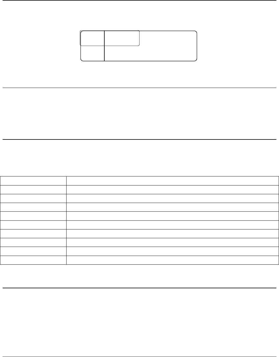
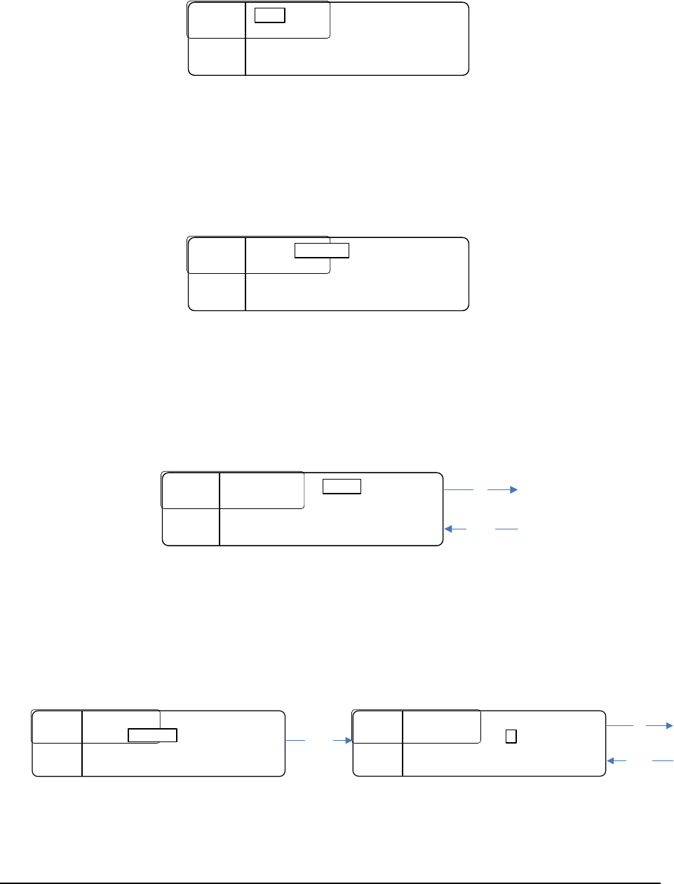
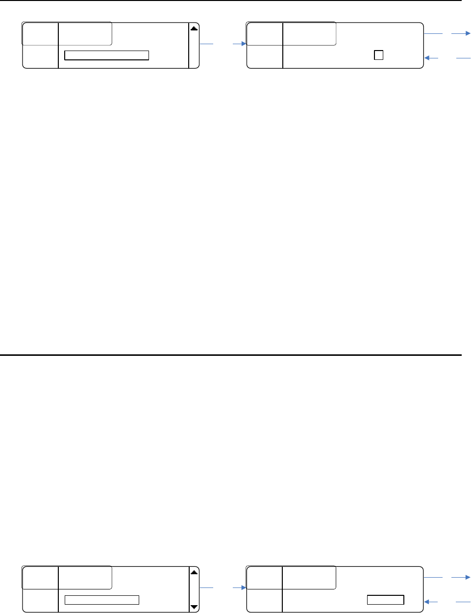
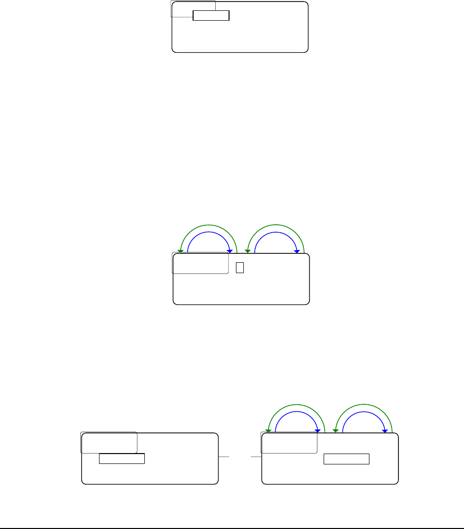
RSSI Screen
To get to the RSSI (Received Signal Strength Indication) screen, press the bottom soft key
labeled RSSI.
R1 R4
R2 R5 OFF
BACK R3 R6 OFF
MENU....M.........
R1 C1...
R4 OFF
MENU
....T1 50mW...R2 C2...
R5 NTx
MENU
....T2 50mW...R3 OFF..R6 W1
RSSI
....HS: OFF
BACK
BACK
RSSI
RSSI
The RSSI screen, shown above, displays the signal strength of each receiver. Presence of the
word OFF means that particular receiver is disabled.
20
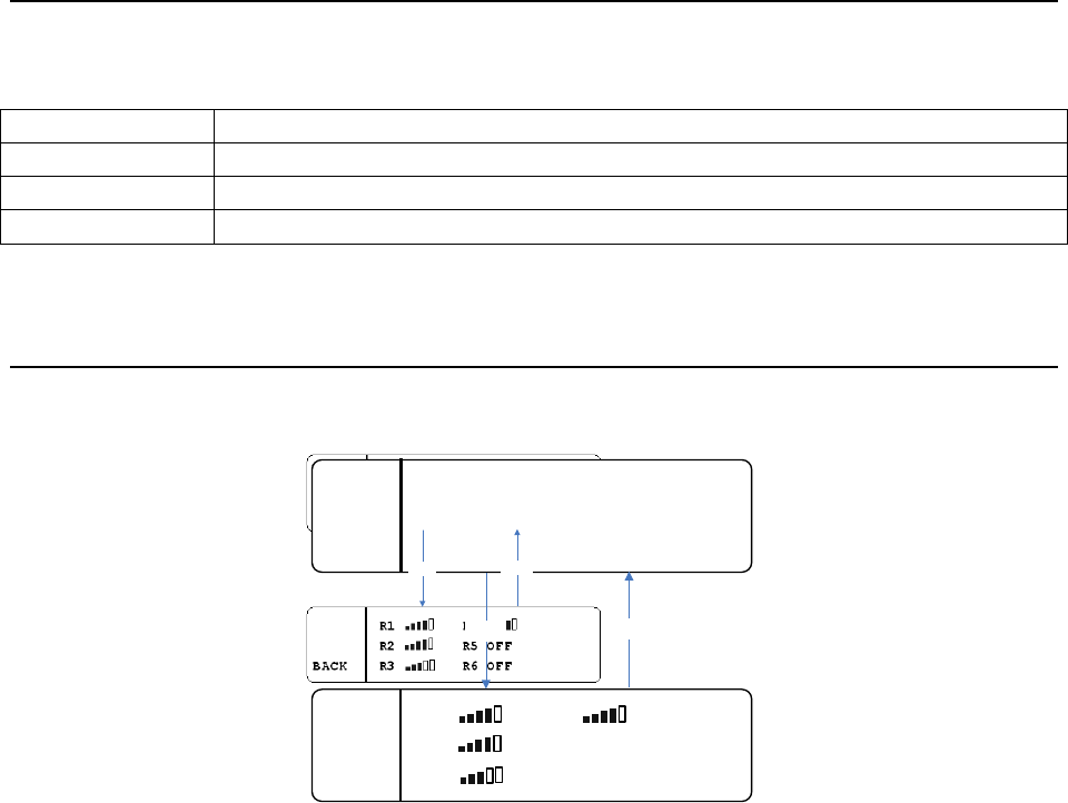
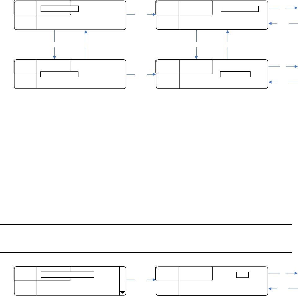
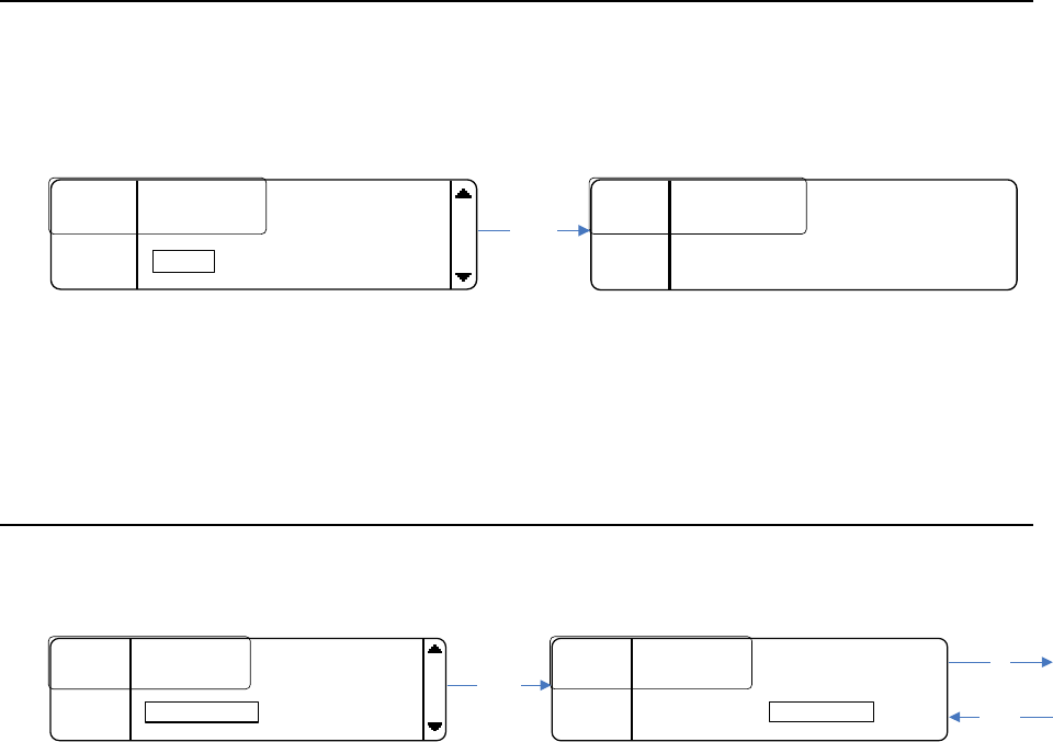
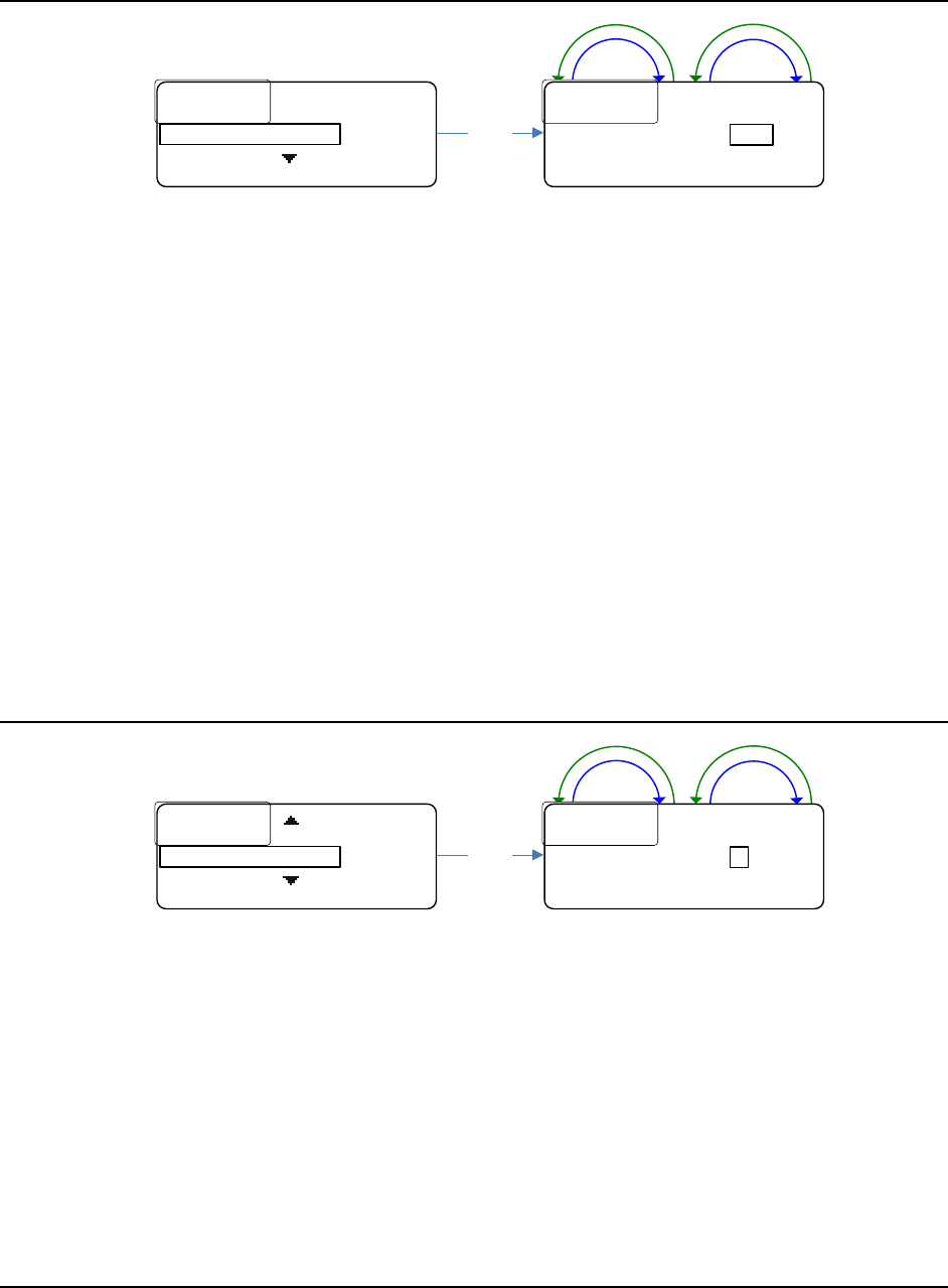
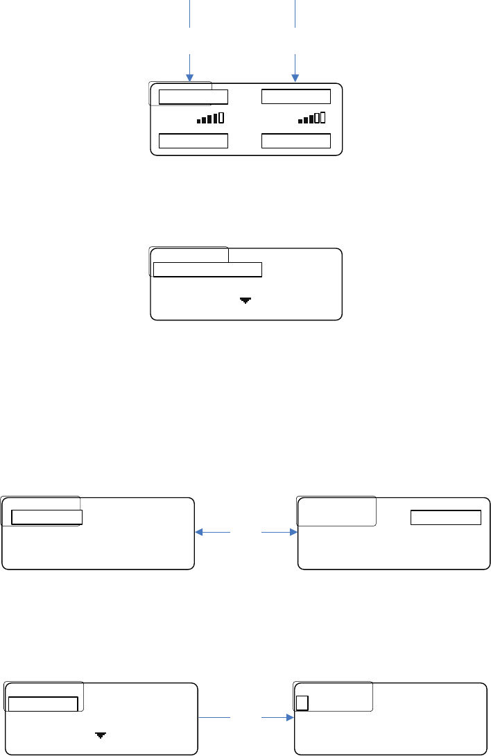
Menu Structure
Passcode Protection
The base station menu can be protected by a passcode.
When the MENU button is pressed from the home screen the screen will change as follows:
BACK
MENU
MENU....M.........R1 C1...R4 OFF
MENU....T1 50mW...R2 C2...R5 NTx
MENU....T2 50mW...R3 OFF..R6 W1
RSSI....HS: OFF
INFO......Enter the Passcode:
MENU....
MENU........0....*....*....*
BACK....
*
*
The passcode is four digits long and each digit can be any 0 – 9 number.
• Press SELECT to change the selected (boxed) digit.
• Once the last digit is entered, press SELECT.
If the entered passcode is correct, the menu screen will be displayed. If it is incorrect,
“Invalid Passcode” will be displayed for three seconds before returning to the home screen.
See ENABLING/DISABLING THE PASSCODE and CHANGING THE PASSCODE for instructions
on how to enable/disable and change the passcode.
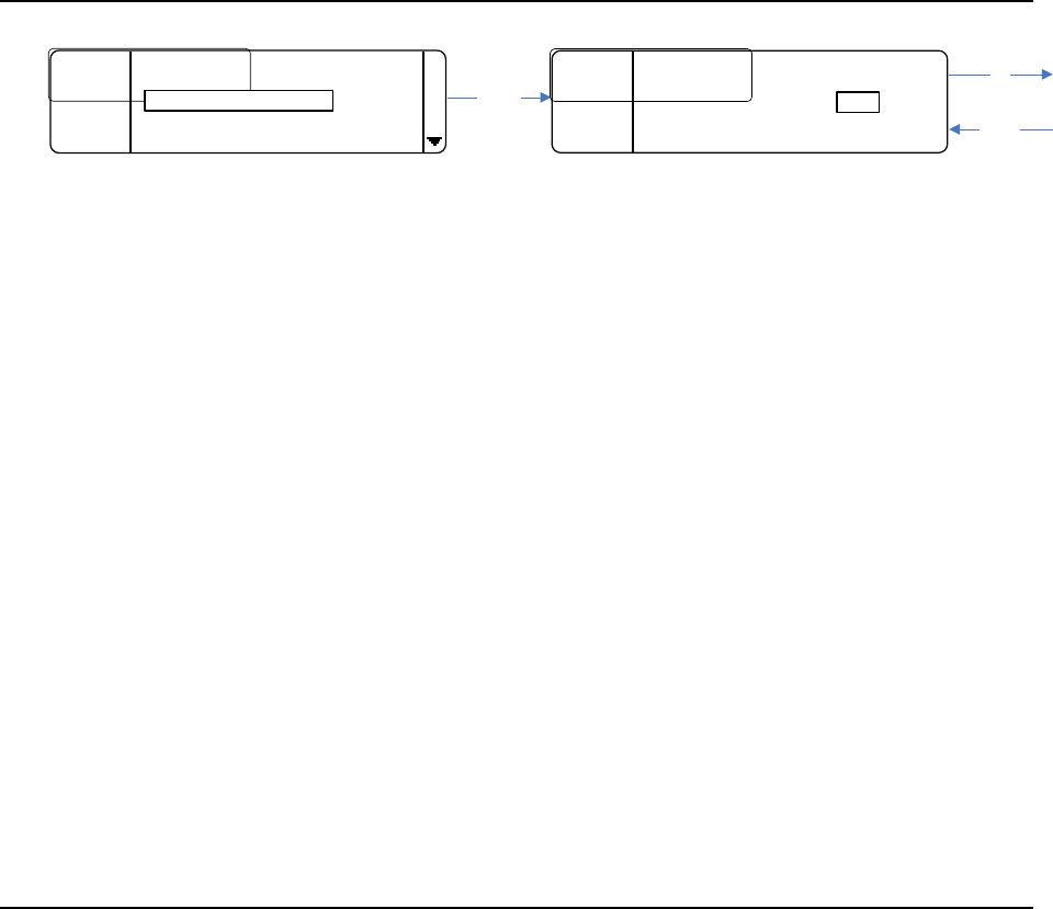
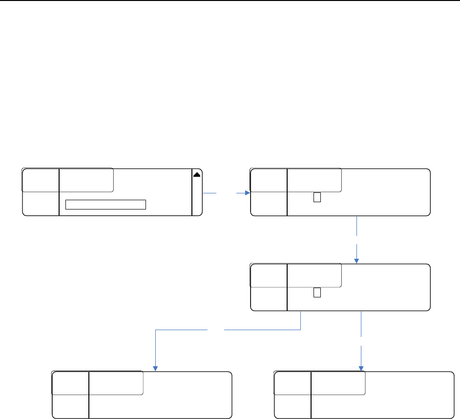
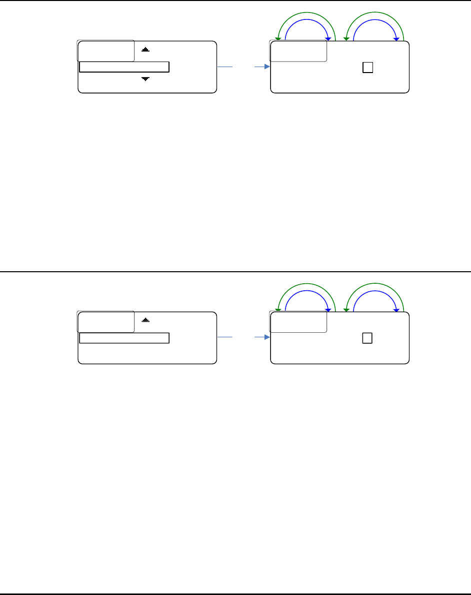
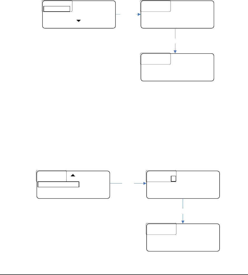
Receiver Settings
The receiver settings allow the user to change the receiver frequencies, as well as enable or
disable them.
To get to the receiver settings, from the home screen, press MENU then press SELECT on RX
SETTINGS. The screen will appear as follows:
............
............
179
179
.
.
450
450
........
........
R
R
2
2
:
:
202
202
.
.
020
020
BACK
BACK
....
....
R
R
3
3
:
:
215
215
.
.
300
300
R1:
21
This screen displays the frequency (in MHz) of all six receivers.
If a given receiver is disabled, the word DISABLED will appear in place of a numerical
frequency value.
• Use the rotary encoder to navigate to the desired receiver and press SELECT to
change the receiver frequency or status (enabled / disabled).
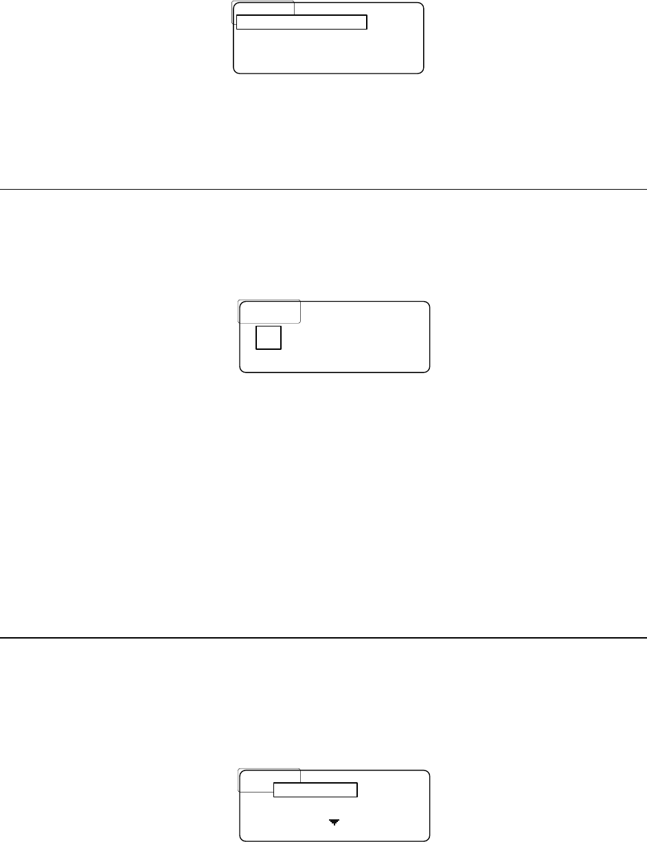
The following is an example of selecting R1:
........
........
R
R
1
1
Freq
Freq
:
:
179
179
.
.
450
450
........
........
Status
Status
:
:
Enabled
Enabled
........
........
BACK
BACK
....
....
Freq :
• To change the frequency, press SELECT and the first frequency digit will be boxed
(see below).
• Use the encoder to change the value of the boxed digit (up / down).
• Press SELECT to move on to the next digit.
• Once the frequency has been changed as desired, press SAVE to save the change or
BACK to cancel.
SAVE
SAVE
....
....
R
R
1
1
Freq
Freq
:
:
1
1
79
79
.
.
450
450
........
........
Status
Status
:
:
Enabled
Enabled
........
........
BACK
BACK
....
....
1Up
Down
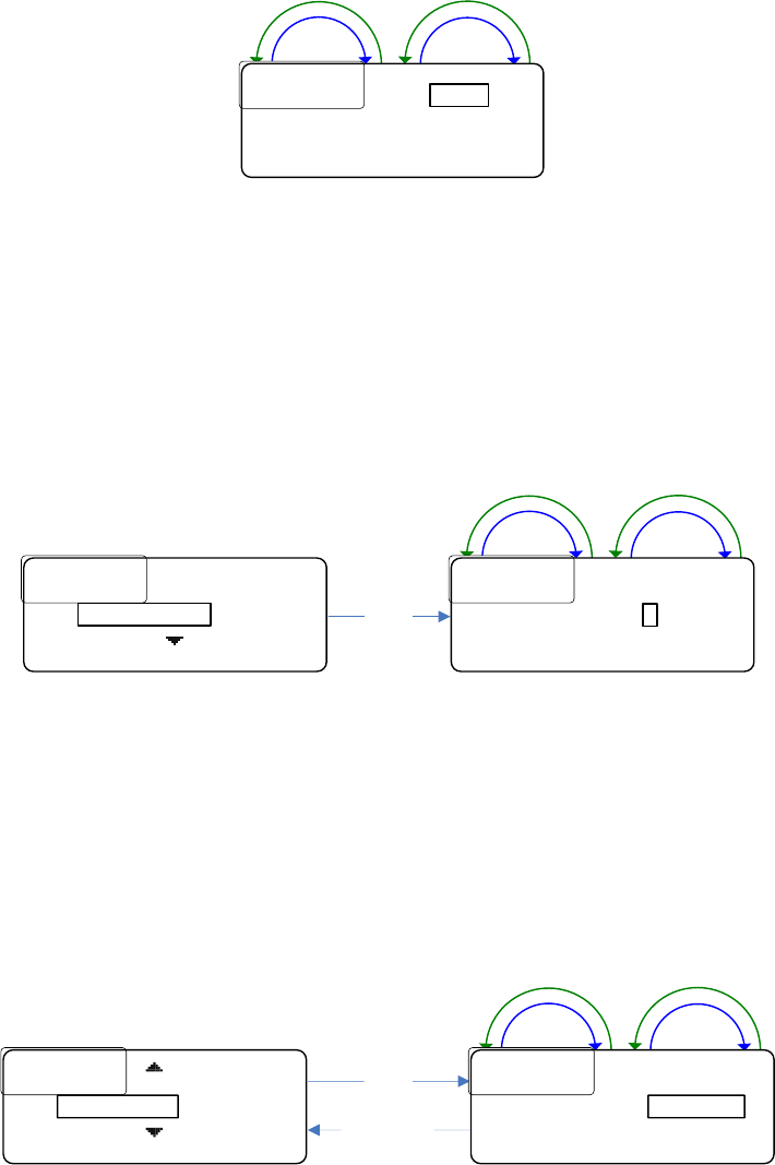
• To change the status, scroll down to STATUS and press SELECT.
• Use the encoder to change the selection and press SAVE to save the change.
........
........
R
R
1
1
Freq
Freq
:
:
179
179
.
.
450
450
........
........
Status
Status
:
:
Enabled
Enabled
........
........
BACK
BACK
....
....
Status:
SAVE
SAVE
....
....
R
R
1
1
Freq
Freq
:
:
179
179
.
.
450
450
........
........
Status
Status
:
:
Enabled
Enabled
........
........
BACK
BACK
....
....
Enabled
Select
Up
Down
Transmitter Settings
The transmitter settings allow the user to change the transmitter frequencies and power
levels as well as enabling/disabling them.
• To get to the transmitter settings from the home screen, press MENU, scroll down
to “Tx Settings,” and press SELECT.
The screen will appear as follows:
22
............
............
50
50
mW
mW
....
....
470
470
.
.
000
000
........
........
T
T
2
2
:
:
50
50
mW
mW
....
....
471
471
.
.
040
040
........
........
BACK
BACK
....
....
T1:
This screen lists the frequency (in MHz) of both transmitters, the power level, and the status
(enabled/disabled). For example if transmitter one is disabled, T1: DISABLED will be displayed.
If it is enabled, then it will be displayed as it is shown above.
• To change any of these settings, scroll to the transmitter you desire to change, press
SELECT and the screen will appear as follows:
........
........
T
T
1
1
..........
..........
50
50
mW
mW
.............
.............
Freq
Freq
:
:
470
470
.
.
000
000
........
........
BACK
BACK
....
....
Power:
• To change the transmitter power, press SELECT.
• Use the encoder to change the value.
• Press SAVE to save or BACK to cancel the change.
SAVE
SAVE
....
....
T
T
1
1
...
...
Power
Power
:
:
.............
.............
Freq
Freq
:
:
470
470
.
.
000
000
........
........
BACK
BACK
....
....
50mW
Up
Down
• To change the frequency, select FREQ and the first frequency digit will be boxed (see
below).
• Use the encoder to change the boxed digit and press SELECT to change which digit is
boxed.
• Press SAVE to save the change or BACK to cancel.
........
........
T
T
1
1
...
...
Power
Power
:
:
50
50
mW
mW
....................
....................
470
470
.
.
000
000
........
........
BACK
BACK
....
....
Freq :
SAVE
SAVE
.....
.....
T
T
1
1
...
...
Power
Power
:
:
50
50
mW
mW
..............
..............
Freq
Freq
:
:
70
70
.
.
000
000
........
........
BACK
BACK
....
....
4
Select
Up
Down
Note: For operation under Part 15 of FCC Rules, the maximum transmitter power is 50mW.
Higher power requires a license under Part 74 of the FCC Rules.
Local Headset Options
There are two local headset options: Status or Earphones.
23
The Status setting allows the local headset to be disabled, set up as listen only, or as a fully
functioning headset (talk and listen).
The Earphone’s setting controls where the receiver audio gets routed, to the left and/or
right earphones.
If Separate is selected, audio from Receiver 1 will be routed to the right earphone and audio
from Receiver 2 will be routed to the left earphone.
If Combined is chosen, audio from both receivers will be routed to both earphones.
Note: If only one receiver is enabled, then the audio from that receiver will be routed to
both earphones no matter what option is chosen. These options are located in the menu under
“Local Headset.”
....................
....................
Talk
Talk
/
/
Listen
Listen
BACK
BACK
....
....
Earphones
Earphones
:
:
Combined
Combined
BACK
BACK
....
....
Status :
SAVE
SAVE
....
....
Status
Status
:
:
.
.
Talk
Talk
/
/
Listen
Listen
BACK
BACK
....
....
Earphones
Earphones
:
:
Combined
Combined
BACK
BACK
....
....
Talk/Listen
........
........
Status
Status
:
:
Talk
Talk
/
/
Listen
Listen
BACK
BACK
....
....
Earphones
Earphones
:
:
Combined
Combined
BACK
BACK
....
....
Earphones :
SAVE
SAVE
....
....
Status
Status
:
:
.
.
Talk
Talk
/
/
Listen
Listen
BACK
BACK
....
....
Earphones
Earphones
:
:
Combined
Combined
BACK
BACK
....
....
Combined
Select
Up
Down
Up
Down
Select
Up
Down
Up
Down
Display Settings
Blackout Mode
Select
Up
Down
.........................
.........................
OFF
OFF
........
........
Backlight Time
Backlight Time
:
:
10
10
S
S
BACK
BACK
....
....
LCD
LCD
.
.
Brightness
Brightness
.
.
:
:
3
3
Blackout Mode :
SAVE
SAVE
....
....
Blackout Mode
Blackout Mode
:
:
........
........
Backlight Time
Backlight Time
:
:
10
10
S
S
BACK
BACK
....
....
LCD Brightness
LCD Brightness
:
:
3
3
OFF
24
Blackout Mode allows the user to disable all the LEDs on the base station.
• To get to blackout mode screen, from the home screen, press MENU, scroll down to
Display Settings and press SELECT.
Blackout mode is the first display setting. There are four options: OFF, LEDs, BKLGHT
(backlight), and ON.
ON means that both the backlight and LEDs will be disabled.
OFF means that both the backlight and LEDs operate normally.
LEDs means that just the LEDs will be disabled or blacked out.
BKLGHT means that just the backlight will be disabled or blacked out.
• To change the blackout mode, press SELECT and then turn the encoder as shown
above.
• Press the SAVE button to save the change or press BACK to ignore it.
Backlight Time
Select
Up
Down
........
........
Blackout Mode
Blackout Mode
:
:
OFF
OFF
.........................
.........................
10
10
S
S
BACK
BACK
....
....
LCD Brightness
LCD Brightness
:
:
3
3
Backlight Time :
SAVE
SAVE
....
....
Blackout Mode
Blackout Mode
:
:
OFF
OFF
........
........
Backlight Time
Backlight Time
:
:
BACK
BACK
....
....
LCD Brightness
LCD Brightness
:
:
3
3
10S
The Backlight Time setting changes the amount of time the backlight stays on for.
• To get to the backlight time screen, from the home screen, press MENU, scroll down
to DISPLAY SETTINGS and press SELECT.
Backlight time is the second display setting. Each time any button is pressed or the encoder
is turned the backlight timer gets reset.
The choices are:
5S for 5 seconds
10S for 10 seconds
20S for 20 seconds
30S for 30 seconds
60S for 60 seconds
ON meaning it will never turn off.
• To change the backlight time, press SELECT.
• Turn the encoder as shown above.
• Press SAVE to save the change or BACK to ignore it.
25
LCD Brightness
Select
Up
Down
SAVE
SAVE
....
....
Blackout Mode
Blackout Mode
:
:
OFF
OFF
........
........
Backlight Time
Backlight Time
:
:
10
10
S
S
BACK
BACK
....
....
LCD Brightness
LCD Brightness
:
:
3
........
........
Blackout Mode
Blackout Mode
:
:
OFF
OFF
........
........
Backlight Time
Backlight Time
:
:
10
10
S
S
BACK
BACK
.....................
.....................
3
3
LCD Brightness :
The LCD brightness setting changes the brightness of the LCD’s backlight.
• To get to the LCD brightness screen, from the home screen, press MENU, scroll
down to Display Settings and press SELECT.
LCD Brightness is the third display setting. The choices are 1 – 5, with 1 being dim and 5
being the brightest.
• To change the brightness, press SELECT.
• Turn the encoder as shown above.
• Press SAVE to save the change or press BACK to ignore it.
Note: the brightness updates in real time as it is modified.
LCD Contrast
SAVE
SAVE
....
....
Backlight Time
Backlight Time
:
:
10
10
S
S
........
........
LCD Brightness
LCD Brightness
:
:
3
3
BACK
BACK
....
....
LCD Contrast
LCD Contrast
:
:
7
........
........
Backlight Time
Backlight Time
:
:
10
10
S
S
........
........
LCD Brightness
LCD Brightness
:
:
3
3
BACK
BACK
.....................
.....................
7
7
LCD Contrast :
Select
Up
Down
The LCD contrast setting changes the display’s contrast.
• To get to the LCD contrast screen, from the home screen, press MENU, scroll down
to DISPLAY SETTINGS and press SELECT.
LCD contrast is the fourth display setting. The choices are 1 – 11, with 1 being the dimmest
and 11 being the brightest.
• To change the contrast, press SELECT.
• Turn the encoder as shown above.
• Press SAVE to save the change or press BACK to ignore it.
Note: the contrast updates in real time as it is modified.
26
LED Brightness
........
........
LCD Brightness
LCD Brightness
:
:
3
3
........
........
LCD Contrast
LCD Contrast
:
:
7
7
BACK
BACK
.....................
.....................
3
3
LED Brightness :
SAVE
SAVE
....
....
LCD Brightness
LCD Brightness
:
:
3
3
........
........
LCD Contrast
LCD Contrast
:
:
7
7
BACK
BACK
....
....
LED Brightness
LED Brightness
:
:
3
Select
Up
Down
The LED brightness setting changes the talk buttons LED’s brightness.
• To get to the LED brightness screen, from the home screen, press MENU, scroll
down to Display Settings and press SELECT.
LED brightness is the last display setting. The choices are 1 – 5, with 1 being the dimmest
and 5 being the brightest.
• To change the brightness, press SELECT.
• Turn the encoder as shown above.
• Press SAVE to save the change or press BACK to ignore it.
Note: the brightness updates in real time as it is modified.
Base Station Link Modes
Two base stations can be “linked” together to expand the number of belt packs that the
system can handle.
The two options are Master and Slave. When two base stations are “linked” together, one
must be set up as a master and the other as a slave.
The master base station works just like a normal base station except it will receive audio
from the slave base station that it will route.
The slave base station receives up to six belt packs’ audio and gives it to the master to
route. The slave’s transmitters and all the ports on the back of the base station will be disabled.
• To change the base station link mode, go to LINK SETTINGS in the menu, and press
SELECT.
• Turn the encoder to the desired setting and
• press SAVE.
EXIT
EXIT
....
....
Local Headset
Local Headset
........
........
Display Settings
Display Settings
........
........
Master
Master
Link Settings:
SAVE
SAVE
....
....
Local Headset
Local Headset
........
........
Display Settings
Display Settings
BACK
BACK
....
....
Link Settings
Link Settings
:
:
Master
Master
Master
Select
Up
Down
27
Info Screen
The Info screen displays a version number and serial number of the base station. The
version number is a composite firmware version number of all the firmware running in the base
station.
........
........
VER
VER
:
:
.
.
XX
XX
.
.
XXX
XXX
........
........
SN
SN
.
.
:
:
.
.
XXXXXXXX
XXXXXXXX
BACK
BACK
Select
EXIT
EXIT
....
....
Display Settings
Display Settings
........
........
Link Settings
Link Settings
:
:
Master
Master
Info
The Info screen is located in the menu right below LINK SETTINGS. To view the screen,
press SELECT as shown above.
Enabling/Disabling the Passcode
The Menu can be passcode protected. The passcode is a four digit 0 – 9 number.
EXIT
EXIT
....
....
Link Settings
Link Settings
:
:
Master
Master
........
........
Info
Info
........
........
Passcode
Passcode
:
:
Disabled
Disabled
Passcode:
SAVE
SAVE
....
....
Link Settings
Link Settings
:
:
Master
Master
........
........
Info
Info
BACK
BACK
....
....
Passcode
Passcode
:
:
Disabled
Disabled
Disabled
Select
Up
Down
The passcode can be enabled or disabled from the PASSCODE screen. It is located below
the Info screen in the Menu as shown above.
• To change the setting, press SELECT.
• Turn the encoder until the desired option appears
• Press SAVE.
28
Changing the Passcode Combine Passcode Sections?
The Passcode can be changed by selecting Change Passcode in the Menu.
• Select Change Passcode
• Enter the desired new passcode (pressing SELECT to advance to the next digit)
• Press SAVE
• Re-enter the desired new passcode
• Pressing SAVE once finished.
If the two passcodes that were just entered match, then the passcode will be changed to
that value. If they don’t match, then the passcode will remain unchanged.
EXIT
EXIT
....
....
Info
Info
........
........
Passcode
Passcode
:
:
Disabled
Disabled
........
........
Change Passcode
SAVE
SAVE
......
......
Enter New Passcode
Enter New Passcode
:
:
MENU
MENU
....
....
MENU
MENU
........
........
0
0
....
....
*
*
....
....
*
*
....
....
*
*
BACK
BACK
....
....
*
SAVE
SAVE
.....
.....
Re
Re
-
-
enter New Passcode
enter New Passcode
:
:
MENU
MENU
....
....
MENU
MENU
........
........
0
0
....
....
*
*
....
....
*
*
....
....
*
*
BACK
BACK
....
....
*
BACK
BACK
....
....
MENU
MENU
....
....
Error
Error
:
:
Passcodes don’t
Passcodes don’t
MENU
MENU
....
....
match
match
.
.
BACK
BACK
....
....
EXIT
EXIT
....
....
MENU
MENU
.......
.......
Passcode
Passcode
.
.
Changed
Changed
.
.
MENU
MENU
....
....
BACK
BACK
....
....
Select
Save
Save
Save
29
Gain Adjustments
Gain adjustments can be made to the following:
Intercom 1 inputs and outputs (2W and 4W)
Auxiliary inputs and outputs, and
Stage Announce (and the local headset microphone which is described in the Local Headset
section)
All gains have eleven (11) settings.
• To change one of the gain settings, press the appropriate gain button and then use
the encoder to adjust it.
The gain screen will go away after 30 seconds if no button press or encoder knob turn is
made.
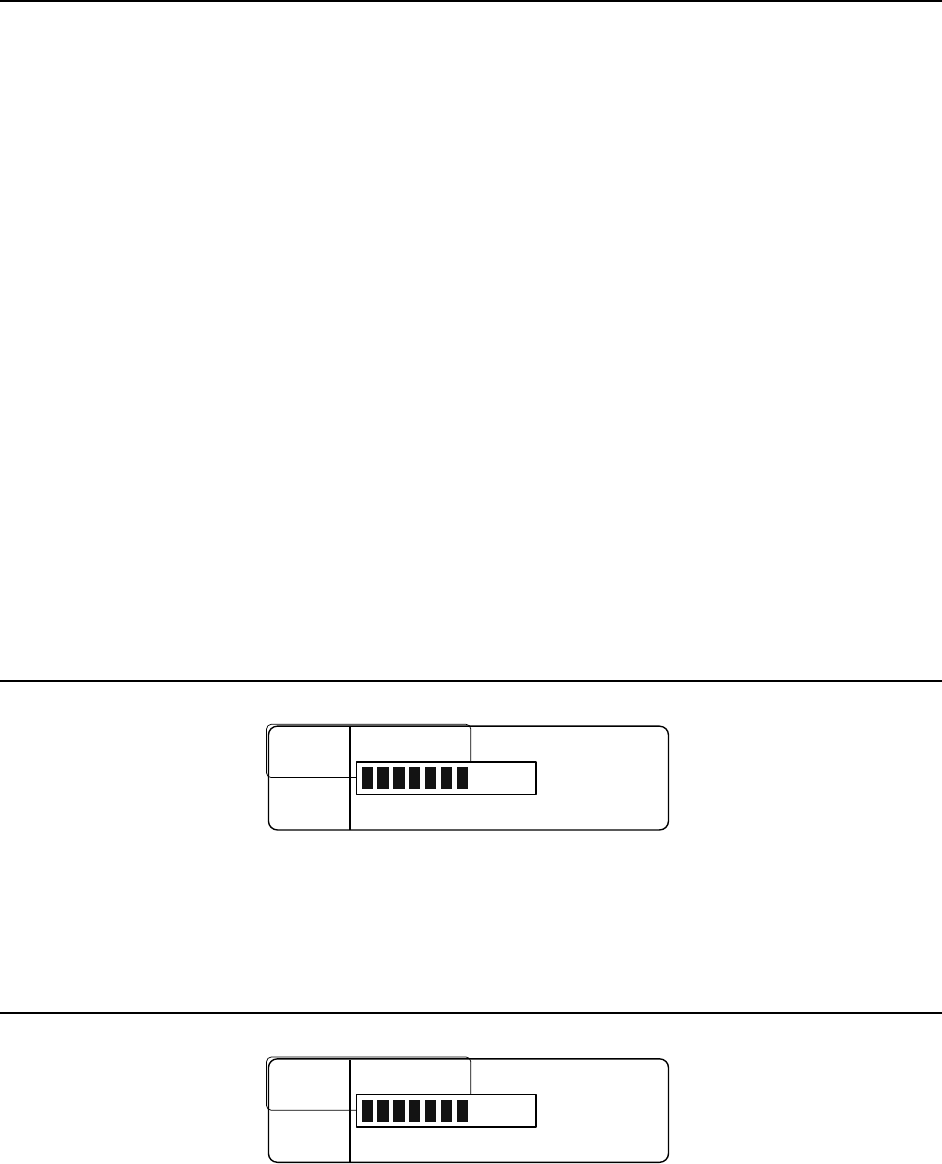
When changing one of the gains a bar graphic along with a number will be displayed on the
screen to show the current setting.
A label telling what gain it is and a status (when applicable) is also shown.
• Turn the encoder knob clockwise to increase the gain and counter clockwise to
decrease the gain. The change will take place immediately.
• When finished, press SAVE to save the change, otherwise press BACK, or wait for the
timeout to cancel any changes (the value will revert back).
Note: Stage Announces’ gain can be changed at anytime, however Intercom 1 and 2 and
Auxiliary need to be enabled to be able to change their gains.
Intercom 1 & 2
SAVE
SAVE
...
...
COM
COM
1 4
1 4
W Input Gain
W Input Gain
BACK
BACK
...
...
Status
Status
:
:
Enabled
Enabled
7
The figure above shows an example of what an Intercom gain screen looks like. Note: the
Intercom must be enabled to change the gain.
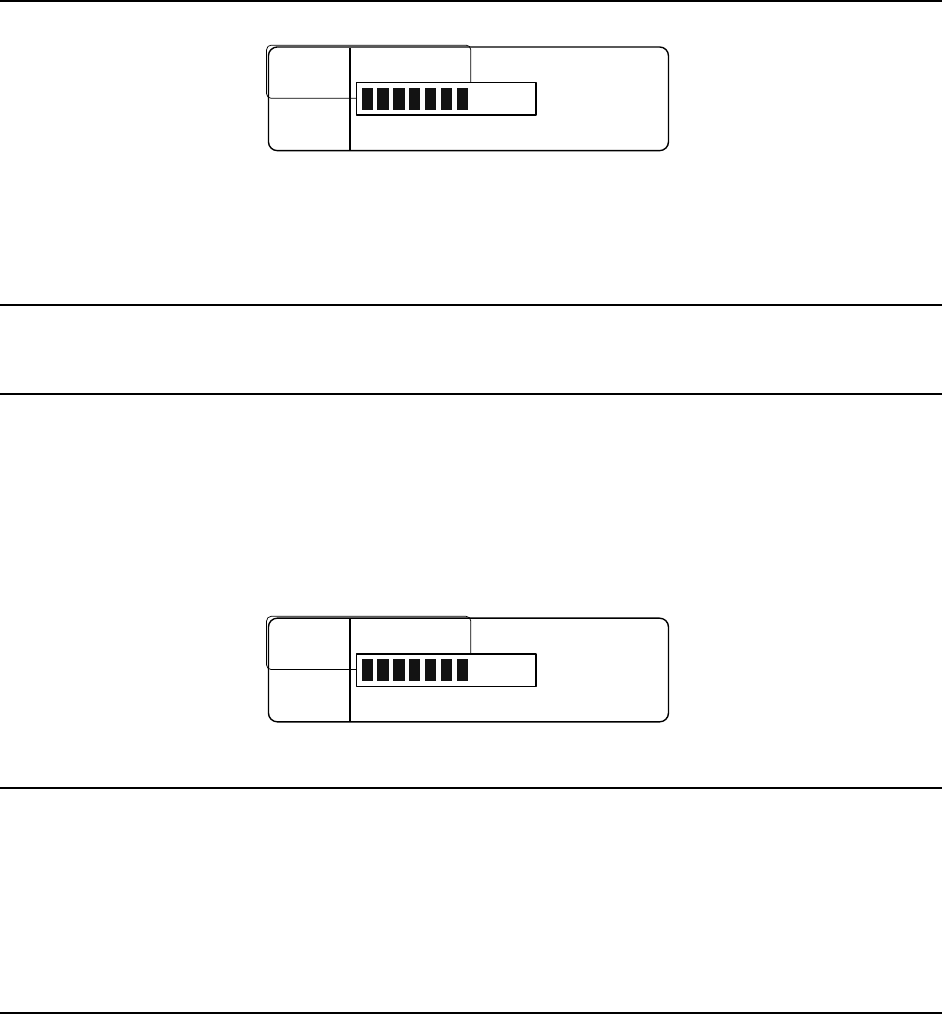
Auxiliary
SAVE
SAVE
...
...
Aux Input Gain
Aux Input Gain
BACK
BACK
...
...
Status
Status
:
:
Enabled
Enabled
7
30
The figure above shows an example of what an Auxiliary gain screen looks like. Note:
Auxiliary must be enabled to change the gain.
Stage Announce
SAVE
SAVE
...
...
SA Gain
SA Gain
BACK
BACK
...
...
7
The figure above shows what the Stage Announce gain screen looks like.
Local Headset
Microphone Gain
• Change the local headset microphone gain by pressing the Mic Level button (below
the Talk button).
The display will change as shown below.
• Use the encoder to change the gain, and press SAVE to save the change or BACK to
ignore it.
Note: the microphone gain updates in real time as it is modified.
SAVE
SAVE
...
...
Mic Gain
Mic Gain
BACK
BACK
...
...
7
Volume
The local headset volume is control by a knob, located to the right of the TALK and MIC
level buttons.
31
Intercom CH1 and CH2 Buttons and LEDs
These two buttons allows the base station user to transmit on Intercom Channel 1,
Intercom Channel 2 or both.
When enabled the audio will be routed through that intercom channel (and not routed
when it is disabled).
There are two LEDs above each of these buttons:
• The one on the left is a green LED that is on when that channel is enabled and off
when disabled.
• The LED on the right is a red and green LED combo. It is green when that intercom
channel’s audio is being routed and the talk button is pressed and red when this is
true plus the user’s microphone is over modulating.
Talk Button
The Talk button allows the base station user to transmit. The button can be pressed and
held or “tapped” on and off.
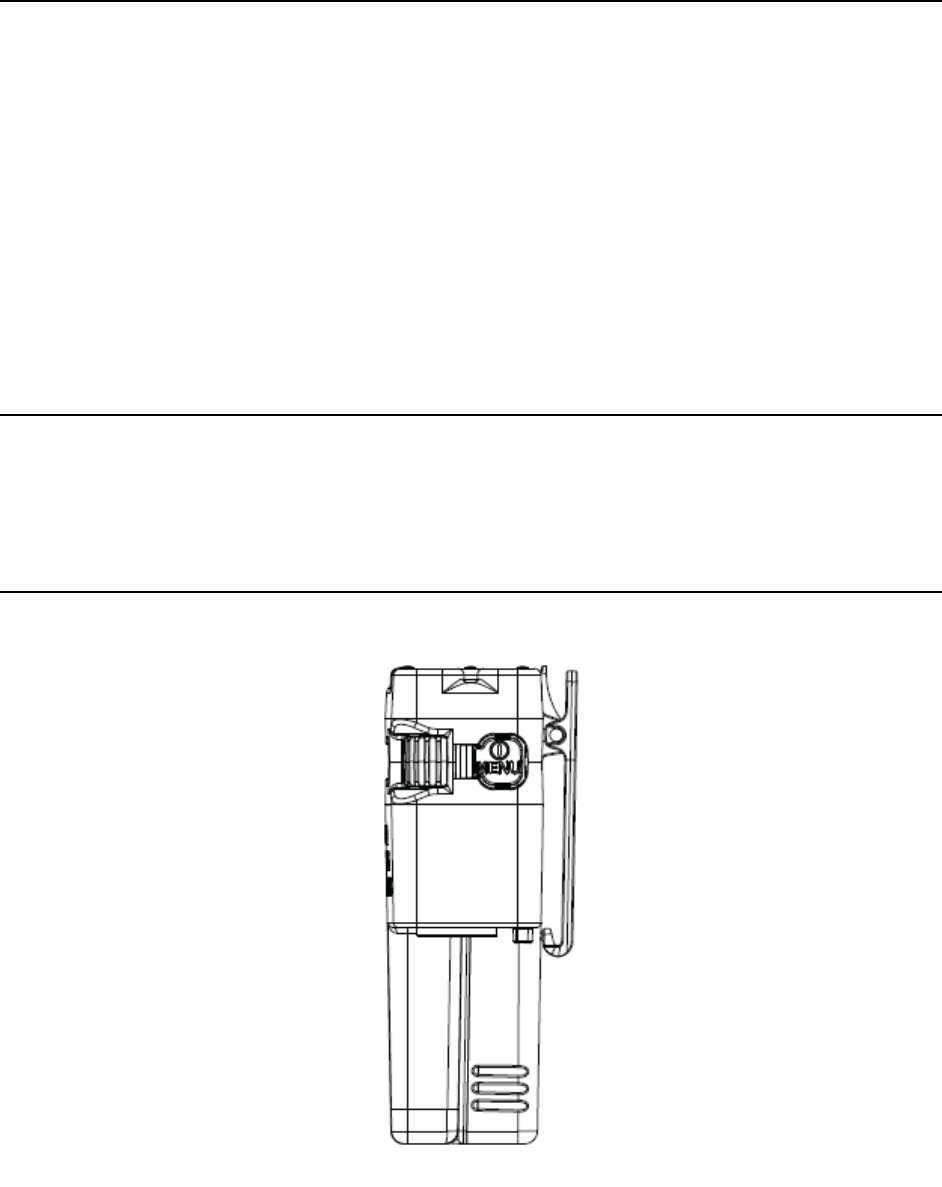
Belt Pack Operation
Figure 8 Belt Pack Power Button

32
Battery
Before the belt pack is turned on, be sure to attach a fresh battery pack. During operation,
the battery meter will display the battery’s status.
Powering Up
To turn the belt pack on, press the power button as shown in Figure 8 above. While the belt
pack is powering on, a splash screen will be displayed.
RADIO
ACTIVE
DESIGNS . . .
Once the belt pack is ready to go, the home screen will be displayed.
Powering Down
To turn the belt pack off, press and hold (approximately 3 seconds) the power button until
the LCD screen goes blank.

33
Home Screen
Talk Buttons and LEDs
The belt pack has four talk buttons with a corresponding set of green and red LEDs.
The top two talk buttons, Intercom Channel 1 and Intercom Channel 2, are fixed in
functionality although the label names are programmable.
The bottom two talk buttons are programmable with the following choices:
• Intercom Channels (CH) 1 & 2
• Wireless-Talk-Around (WTA) 1
• Wireless-Talk-Around (WTA) 2
• Wireless-Talk-Around (WTA) 1 & 2
• Stage Announce (SA).
The home screen displays this information in the four boxes in the corners of the screen.
Each talk button has a green and red LED set.
The green LED turns on to show that the transmitter is active for that channel.
The red LED turns on when microphone over modulation occurs while transmitting.
Intercom and Programmable Button Labels
The home screen displays a boxed “T” next to each talk button label box to show the
transmitter’s status for each button.
The “T” means that the transmitter is on, and a box around the “T” means that the mic is
unmuted.
Note: it is possible to turn on the transmitter with the microphone muted (no audio is
transmitted).
Signal and Battery Meters
The signal and battery meters are there to assist the user.
The signal meter is an average of both receiver’s signal strength if both are enabled, or if
just one receiver is enabled it is that receiver’s signal strength.
The battery meter displays the battery’s status.
Local Headset Volume
The headset volume is changeable via the two knobs:
• Left changes Channel One
• Right changes Channel Two
If the local headset volume option is set to COMBINED, both knobs change volume of both
receivers proportionally.
34
Power / Menu Button
This button is used to turn on and off the belt pack, as well as to get into and out of the
menu.
• When the belt pack is off, press the button to turn it on.
• When on, press and hold (approximately 3 seconds) to turn it off.
• To get into or out of the menu, when the belt pack is on, press (without holding) the
button.
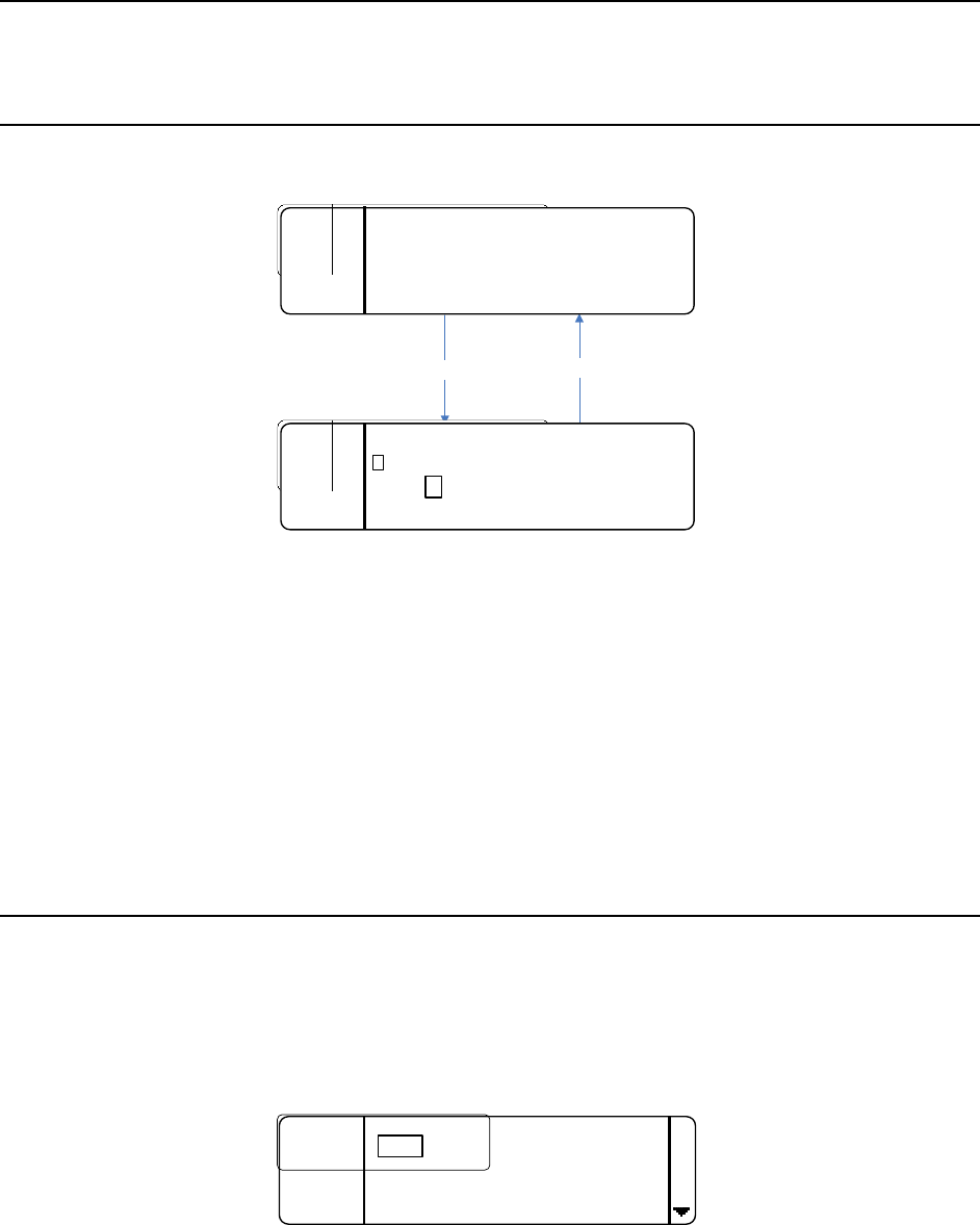
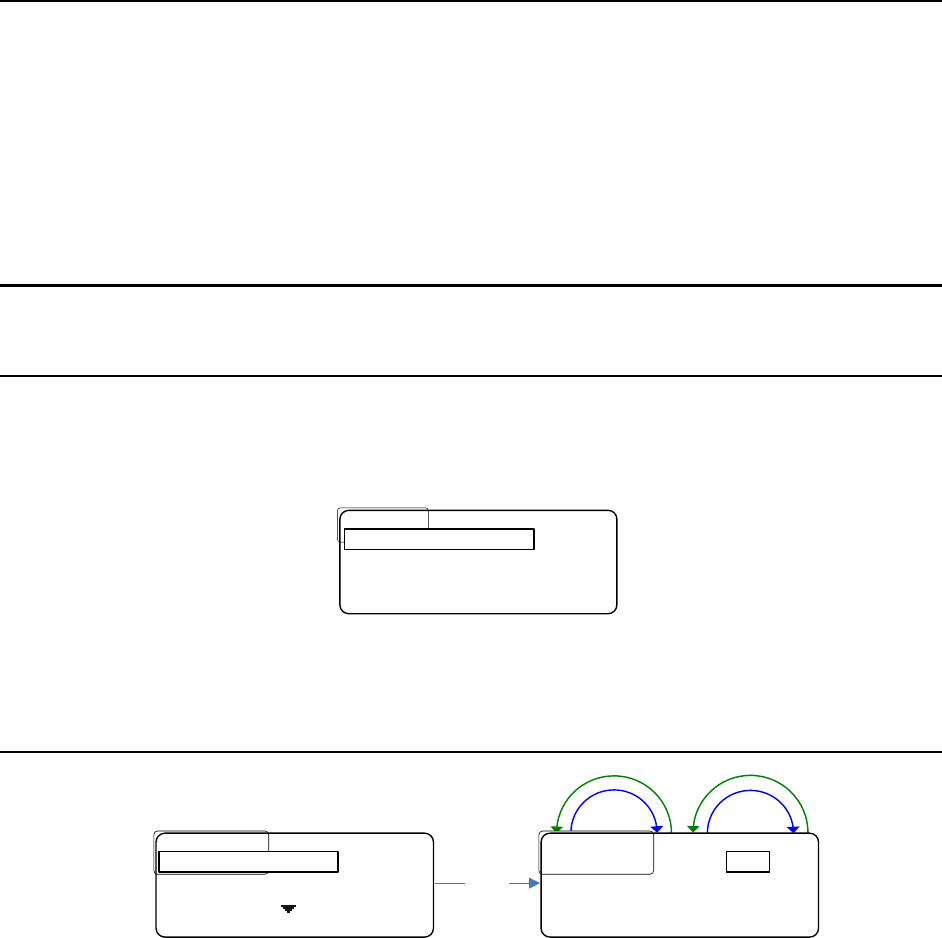
Menu Structure
Display Settings
• To get to the display settings from the home screen, press the MENU button.
The screen will appear as follows:
Advanced Settings
Advanced Settings
Exit
Exit
<
<
BP
BP
ID
ID
>
>
Mic
Mic
G
G
Display Settings
• Press SELECT.
Blackout Mode
Down
Up
Down
Up
Select
Blackout
Blackout
.
.
Mode
Mode
.
.
:
:
Backlight
Backlight
.
.
Time
Time
:
:
10
10
S
S
SAVE BACK
SAVE BACK
OFF
................
................
OFF
OFF
Backlight
Backlight
.
.
Time
Time
:
:
10
10
S
S
BACK
BACK
Blackout Mode :
Blackout mode is the first display setting. It allows the LCD backlight and/or the talk LEDs to
be disabled or “blacked out”.
There are four options: OFF, LEDs, BKLGHT (backlight), and ON.
ON means that both the backlight and LEDs will be disabled, and
OFF means that both the backlight and LEDs operate normally.
LEDs means the LEDs will be disabled or blacked out, and likewise
BKLGHT means the backlight will be disabled or blacked out.
• To change the blackout mode, press SELECT
• turn either encoder as shown above.
• Press SAVE to save the change or BACK to ignore it.
35
Backlight Time
Down
Up
Down
Up
Select
Blackout
Blackout
.
.
Mode
Mode
:
:
OFF
OFF
Backlight
Backlight
.
.
Time
Time
:
:
SAVE BACK
SAVE BACK
10S
Blackout
Blackout
.
.
Mode
Mode
.
.
:
:
.
.
OFF
OFF
................
................
10
10
S
S
BACK
BACK
Backlight Time:
The backlight time setting changes the amount of time the backlight stays on for.
Each time any button is pressed or encoder is turned the backlight timer gets reset.
The choices are:
5S for 5 seconds
10S for 10 seconds
20S for 20 seconds
30S for 30 seconds
60S for 60 seconds
ON meaning it will never turn off.
• To change the backlight time, press SELECT
• turn either encoder as shown above.
• Press SAVE to save the change or BACK to ignore it.
LCD Brightness
Down
Up
Down
Up
Select
Backlight
Backlight
.
.
Time
Time
:
:
.
.
10
10
S
S
LCD
LCD
.
.
Brightness
Brightness
:
:
SAVE BACK
SAVE BACK
3
Backlight
Backlight
.
.
Time
Time
:
:
10
10
S
S
................
................
3
3
BACK
BACK
LCD.Brightness:
The LCD brightness setting changes the brightness of the LCD’s backlight.
The choices are 1 – 5, with 1 being the dimmest and 5 being the brightest.
• To change the brightness, press SELECT
• Turn either encoder as shown above.
• Press SAVE to save the change or BACK to ignore it.
Note: the brightness updates in real time as it is modified.
36
LCD Contrast
Down
Up
Down
Up
Select
LCD
LCD
.
.
Brightness
Brightness
:
:
3
3
LCD
LCD
.
.
Contrast
Contrast
..
..
:
:
SAVE BACK
SAVE BACK
7
LCD
LCD
.
.
Brightness
Brightness
:
:
.
.
3
3
................
................
7
7
BACK
BACK
LCD Contrast :
The LCD contrast setting changes the display’s contrast.
The choices are 1 – 11, with 1 being the dimmest and 11 being the brightest.
• To change the contrast, press SELECT
• Turn either encoder as shown above.
• Press SAVE to save the change or BACK to ignore it.
Note: the contrast updates in real time as it is modified.
LED Brightness
Down
Up
Down
Up
Select
LCD
LCD
.
.
Contrast
Contrast
:
:
7
7
LED
LED
.
.
Brightness
Brightness
:
:
SAVE BACK
SAVE BACK
3
LCD
LCD
.
.
Contrast
Contrast
:
:
7
7
................
................
3
3
BACK
BACK
LED Brightness:
The LED brightness setting changes the talk buttons LED’s brightness.
The choices are 1 – 5, with 1 being the dimmest and 5 being the brightest.
• To change the brightness, press SELECT
• Turn either encoder as shown above.
• Press SAVE to save the change or BACK to ignore it.
Note: the brightness updates in real time as it is modified.
Advanced Settings
• To get to the advanced settings, from the home screen, press the MENU button.
37
The screen will look like this:
Advanced Settings
Advanced Settings
Exit
Exit
<
<
BP
BP
ID
ID
>
>
Mic
Mic
G
G
Display Settings
• Use either encoder to scroll down to Advanced Settings.
• Once it is boxed, press SELECT.
Passcode Protection
The advanced menu can be passcode protected if desired.
When the passcode is enabled, once the user presses select on ADVANCED SETTINGS, the
screen will appear as follows:
....
....
Enter
Enter
.
.
Passcode
Passcode
:
:
.
.
*
*
..
..
*
*
..
..
*
*
..
..
*
*
INFO
INFO
..............
..............
BACK
BACK
*
The passcode is four digits where each digit can be any 0 – 9 number.
• Use either encoder to change the selected digit.
• Press SELECT to change the selected (boxed) digit.
• Once the last digit is entered press SELECT.
If the entered passcode is correct the belt pack will go to the advanced settings.
If it is incorrect Invalid Passcode will be display for three seconds before returning to the
main menu.
See ENABLING/DISABLING THE PASSCODE and/or CHANGING THE PASSCODE at the end of
this section for more information.
Transmitter Settings
The transmitter settings allow the user to change the transmitter power level, frequency,
status, and Intercom transmit settings.
The transmitter settings are located in the ADVANCED SETTINGS sub-menu.
Once selected, the screen will appear as follows:
T
T
1
1
.............
.............
50
50
mW
mW
....
....
Freq
Freq
.....
.....
:
:
.
.
214
214
.
.
000
000
..................
..................
BACK
BACK
Power :
38
• To change the transmitter power level, press SELECT.
• Use either encoder to change the value and press SAVE to save or BACK to ignore
the change.
The choices are 10mW and 50mW.
Down
Up
Down
Up
T
T
1
1
..
..
Power
Power
....
....
:
:
....
....
Freq
Freq
.....
.....
:
:
.
.
214
214
.
.
000
000
SAVE
SAVE
..............
..............
BACK
BACK
50mW
• To change the frequency, scroll down to box FREQ: press SELECT and the first
frequency digit will be boxed (see below).
• Use either encoder to change the boxed digit
• Press SELECT to change which digit is boxed.
• Press SAVE to save the change or BACK to ignore it.
The belt pack transmitter frequency range is 174 MHz – 216 MHz (VHF), and the step size if
5 kHz.
Down
Up
Down
Up
Select
T
T
1
1
..
..
Power
Power
....
....
:
:
.
.
50
50
mW
mW
...............
...............
214
214
.
.
000
000
..................
..................
BACK
BACK
Freq :
T
T
1
1
..
..
Power
Power
....
....
:
:
.
.
50
50
mW
mW
....
....
Freq
Freq
.....
.....
:
:
..
..
14
14
.
.
000
000
SAVE
SAVE
..............
..............
BACK
BACK
2
The status is the “master” control for the transmitter.
If it is set to disabled then the transmitter will be powered down, and all transmit
functionality of the belt pack will be disabled.
If it is set to enabled then the belt pack will function normally, transmitting when a transmit
button is pressed.
• To change the status, scroll down until STATUS: is boxed and press SELECT.
• Use either encoder to change the status and press SAVE to save and BACK to ignore
the change.
Down
Up
Down
Up
Select
Save / Back
T
T
1
1
..
..
Freq
Freq
....
....
:
:
.
.
214
214
.
.
000
000
..............
..............
Enabled
Enabled
..................
..................
BACK
BACK
Status :
T
T
1
1
..
..
Freq
Freq
....
....
:
:
.
.
214
214
.
.
000
000
....
....
Status
Status
..
..
:
:
.
.
Enabled
Enabled
..................
..................
BACK
BACK
Enabled
The last two items in the transmitter settings are called ICOM1 Tx and ICOM2 Tx.
39
These control whether the belt pack user is allowed to transmit on Intercom CH 1 and
Intercom CH 2.
ENABLED = allowed
DISABLED = not allowed
Please note that these don’t affect Wireless-Talk-Around 1 or 2 (they are controlled
separately). They only affect Intercom Channels 1 and 2.
• To change either of these values scroll down until it is boxed and press SELECT.
• Use either encoder to change the status and press SAVE to save and BACK to ignore
the change.
Down
Up
Down
Up
Down
Up
Down
Up
Up/Down
Select
Save / Back
Select
Save / Back
T
T
1
1
..
..
Status
Status
..
..
:
:
.
.
Enabled
Enabled
..............
..............
Enabled
Enabled
..................
..................
BACK
BACK
ICOM1 Tx:
T
T
1
1
..
..
ICOM
ICOM
1
1
.
.
Tx
Tx
:
:
.
.
Enabled
Enabled
..............
..............
Disabled
Disabled
..................
..................
BACK
BACK
ICOM2 Tx:
T
T
1
1
..
..
Status
Status
..
..
:
:
.
.
Enabled
Enabled
....
....
ICOM
ICOM
1
1
.
.
Tx
Tx
:
:
.
.
Enabled
Enabled
..................
..................
BACK
BACK
Enabled
T
T
1
1
..
..
ICOM
ICOM
1
1
.
.
Tx
Tx
:
:
.
.
Enabled
Enabled
....
....
ICOM
ICOM
2
2
.
.
Tx
Tx
:
:
.
.
Disabled
Disabled
..................
..................
BACK
BACK
Disabled
Receiver Settings
The receiver settings allow the user to change the receiver frequencies as well as
enable/disable them.
The receiver settings are located in the ADVANCED SETTINGS sub-menu.
Once selected, the screen will appear as follows:
....
....
470
470
.
.
000
000
R
R
2
2
:
:
498
498
.
.
000
000
BACK
BACK
R1:
This screen lists the frequency (in MHz) of both receivers as well as the status.
For example if receiver one is disabled, R1: Disabled will be displayed.
If a frequency is listed instead of Disabled, then it is enabled and receiving at the specified
frequency.
• To change a receivers’ frequency or status, scroll to the receiver you desire to
change
40
• Press SELECT and the screen will change to the following:
R
R
1
1
.
.
Freq
Freq
..:.
..:.
470
470
.
.
000
000
...
...
Status
Status
:
:
.
.
Enabled
Enabled
BACK
BACK
Freq:
• To change the frequency, press SELECT and the first frequency digit will be boxed
(see below).
• Use the encoder to change the boxed digit and press SELECT to change which digit is
boxed.
• Once the frequency has been changed as desired, press SAVE to save the change or
BACK to ignore it.
The belt pack receiver frequency range is 470-608MHz and– 614-698MHz (UHF), and the
step size is 5kHz.
Down
Up
Down
Up
R
R
1
1
.
.
Freq
Freq
..
..
:
:
.
.
4
4
70
70
.
.
000
000
...
...
Status
Status
:
:
.
.
Enabled
Enabled
SAVE BACK
SAVE BACK
4
The status enables (turns on) / disabled (turns off) the receiver.
Turn off an un-needed receiver to save battery power.
• To change the status, scroll down to box Status and press SELECT.
• Turn the encoder to change the selection
• Press SAVE to save the change.
Down
Up
Down
Up
Select
R
R
1
1
.
.
Freq
Freq
..
..
:
:
.
.
470
470
.
.
000
000
...
...
Status
Status
:.
:.
Enabled
Enabled
BACK
BACK
Status:
R
R
1
1
.
.
Freq
Freq
..
..
:
:
.
.
470
470
.
.
000
000
...
...
Status
Status
:
:
.
.
Enabled
Enabled
SAVE BACK
SAVE BACK
Enabled
Channel Labels
The Channel Labels menu option in the Advanced Settings sub-menu provides a way to
change the (Intercom) Channel talk button labels.
41
SIG
SIG
:
:
BATT
BATT
:
:
CAMERA 1 DIRECTOR
WTA 1&2 SA
Channel 1
Button Label Channel 2
Button Label
This sub-menu allows the user to change, edit, remove, and add new labels. Once the
Channel Labels menu is entered, the screen will appear as follows:
Edit
Edit
/
/
Remove Labels
Remove Labels
BACK
BACK
Change Labels
• Press SELECT to change what label is assigned to each Intercom.
Intercom CH 1 is on the left.
Intercom CH 2 is on the right.
• Press SELECT to change which one gets changed.
• Use either encoder to scroll through the list of labels.
• Press SAVE to save your changes or BACK to ignore them.
Select
Director
Director
SAVE BACK
SAVE BACK
Camera 1
Camera
Camera
1
1
SAVE BACK
SAVE BACK
Director
• To view the label list, or edit or remove a label, select the Edit/Remove Labels
option in the Channel Labels sub-menu.
The screen will appear as follows:
CAMERA
CAMERA
1
1
REMOVE
REMOVE
............
............
BACK
BACK
DIRECTOR Select
.
.
IRECTOR
IRECTOR
SAVE
SAVE
.....
.....
[
[
A
A
-
-
Z
Z
]
]
....
....
BACK
BACK
D
• Use either encoder to scroll through the list.
• Press SELECT to edit the currently selected label.
The left (CH 1) encoder changes the currently selected character.
The right (CH 2) encoder changes the group.
There are three groups: capital letters (A-Z), numbers (0-9), and symbols (SYM).
42
• Press SELECT to change the selected character.
• Press the left soft key labeled REMOVE to remove the currently selected label as
shown below.
Are you sure you want
Are you sure you want
to remove DIRECTOR
to remove DIRECTOR
?
?
NO YES
NO YES
DIRECTOR removed
DIRECTOR removed
!
!
....................
....................
OK
OK
CAMERA
CAMERA
1
1
REMOVE
REMOVE
............
............
BACK
BACK
DIRECTOR Remove
Yes
• To add a label to the list, select the Add New Label option in the Channel Labels
sub-menu.
Labels are allowed to be a maximum of eight characters, and the controls are the same as
editing.
The left (CH 1) encoder changes the currently selected character.
The right (CH 2) encoder changes the group.
There are three groups: capital letters (A-Z), numbers (0-9), and symbols (SYM).
• Press SELECT to change the selected character.
Select
Edit
Edit
/
/
Remove Labels
Remove Labels
BACK
BACK
Add New Label
Joe’s CH added
Joe’s CH added
!
!
....................
....................
OK
OK
Joe’s C
Joe’s C
ADD
ADD
......
......
[
[
A
A
-
-
Z
Z
]
]
....
....
BACK
BACK
H
Add
Soft Button Labels
The Soft Button Labels menu option in the Advanced Settings sub-menu provides a way to
change the soft (programmable) talk buttons.
43
SIG
SIG
:
:
BATT
BATT
:
:
CAMERA 1 DIRECTOR
WTA 1&2 SA
Soft (Programmable)
Button 1 Label Soft (Programmable)
Button 2 Label
There are five options:
Intercom Channels (CH) 1 & 2
Wireless-Talk-Around (WTA) 1
Wireless-Talk-Around (WTA) 2
Wireless-Talk-Around (WTA) 1 & 2
Stage Announce (SA)
• To change one of the buttons, press SELECT on the Soft Button Labels menu option.
The screen will appear as follows:
SA
SA
SAVE BACK
SAVE BACK
WTA 1&2
• Use either encoder to scroll and find the desired option.
• To change the right soft button, press SELECT and the right button label will be
boxed.
• Use either encoder to change the label.
• When done, press SAVE to save the changes or BACK to ignore them.
Rx Volume Options
There are two options for the way the receiver volumes are controlled: Independent and
Master.
If Independent is selected, then the two receiver’s volumes are controlled independently.
At the home screen, the left encoder would control receiver 1 and the right would control
receiver 2.
If Master is selected, then both encoders control the receiver’s volumes. With Master
selected, one receiver will be a ratio of the other (“x” amount of dB higher or lower than the
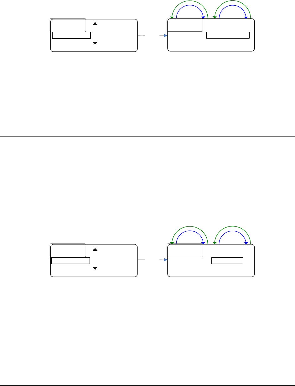
44
other), and turning either encoder will change the volumes appropriately to keep the ratio the
same.
See the PC Application section for more information on the different ratios available.
Down
Up
Down
Up
Select
Soft Button Labels
Soft Button Labels
Rx
Rx
.
.
Volume
Volume
:
:
SAVE BACK
SAVE BACK
Independent
Soft Button Labels
Soft Button Labels
Independent
Independent
BACK
BACK
Rx Volume:
Rx Volume is located under the Advanced Settings sub-menu below Soft Button Labels as
shown above.
• To change the setting, press SELECT
• Turn the encoder until the desired option appears
• Press SAVE.
Headset Options
There are two local headset options: Combined or Separate.
This setting controls where the receiver audio gets routed, to the left and/or right
earphone.
If Separate is selected, audio for receiver 1 will be routed to the right earphone and audio
for receiver 2 will be routed to the left earphone.
If Combined is chosen, audio for both receivers will be routed to both earphones.
Note: if only one receiver is enabled then audio to that receiver will be routed to both
earphones no matter what headset option is chosen.
Down
Up
Down
Up
Rx
Rx
.
.
Volume
Volume
:
:
..
..
Independent
Independent
............
............
Combined
Combined
BACK
BACK
Headset :Select
Rx
Rx
.
.
Volume
Volume
:
:
..
..
Independent
Independent
Headset
Headset
..
..
:
:
SAVE BACK
SAVE BACK
Combined
The headset setting is located under the Advanced Settings sub-menu right below Rx
Volume as shown above.
• To change the setting, press SELECT
• Turn the encoder until the desired option appears
• Press SAVE.
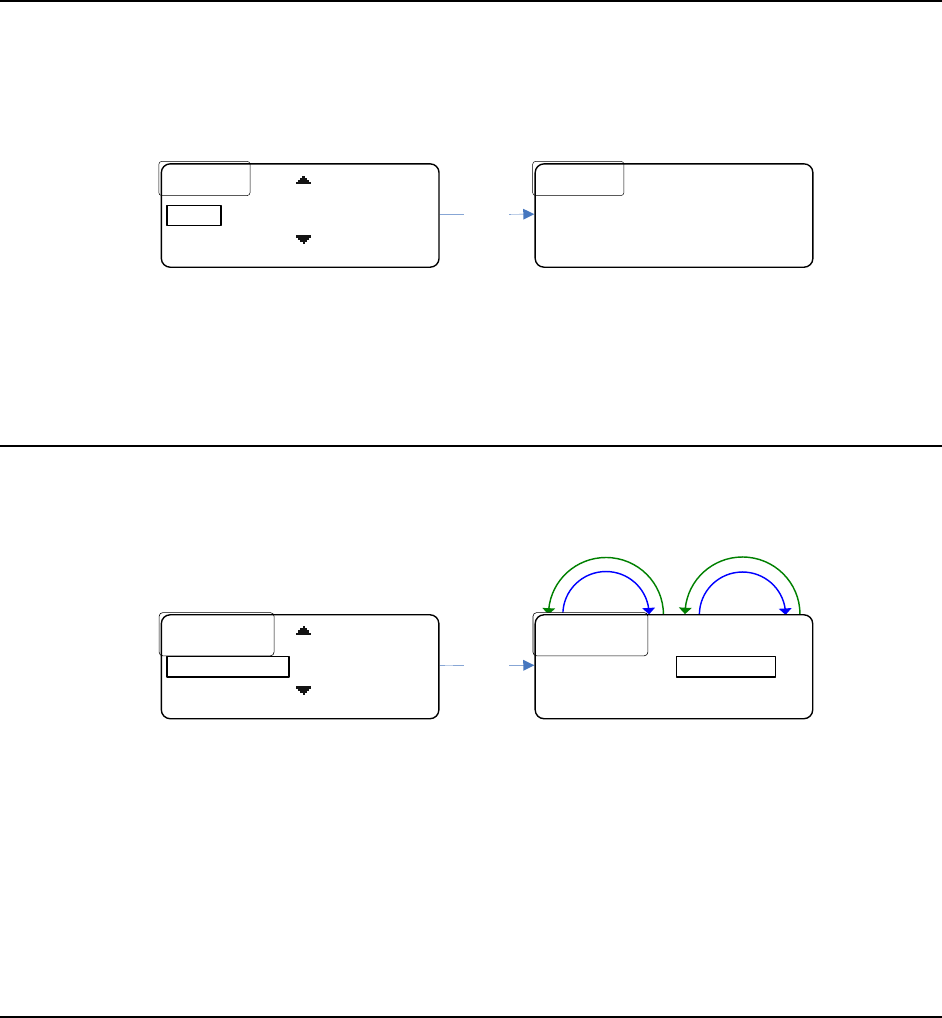
45
Info Screen
The Info screen displays a version number and serial number of the belt pack.
The version number is a composite firmware version number of all the firmware running in
the belt pack.
Select
VER
VER
:
:
XX
XX
.
.
XXX
XXX
SN
SN
:
:
XXXXXXXX
XXXXXXXX
BACK
BACK
Headset
Headset
..
..
:
:
..
..
Combined
Combined
BACK
BACK
Info
The Info screen is located under the Advanced Settings sub-menu right below Headset.
• To view the screen, press SELECT as shown above.
Enabling/Disabling the Passcode
The Advanced Settings sub-menu can be passcode protected.
The passcode is a four digit decimal number (0 – 9).
Down
Up
Down
Up
Select
Info
Info
Passcode
Passcode
.
.
:
:
SAVE BACK
SAVE BACK
Disabled
Info
Info
............
............
Disabled
Disabled
BACK
BACK
Passcode :
The passcode can be enabled or disabled from the Passcode screen.
It is located right below the Info screen in the Advanced Settings sub-menu as shown
above.
• To change the setting, press SELECT,
• Turn the encoder until the desired option appears
• Press SAVE.
Changing the Passcode
The passcode can be changed by selecting Change Passcode in the Advanced Settings sub-
menu.
• Select Change Passcode
• enter the desired new passcode (pressing SELECT to advance to the next digit),
• press SAVE
• re-enter the desired new passcode
• press SAVE once finished.
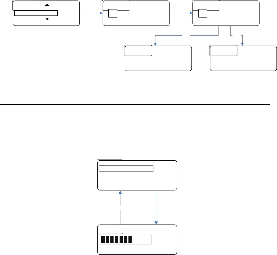
46
If the two passcodes that were just entered match, then the passcode will be changed to
that value.
If they don’t match, then the passcode will remain unchanged.
..
..
Enter
Enter
.
.
New
New
.
.
Passcode
Passcode
:
:
.
.
*
*
..
..
*
*
..
..
*
*
..
..
*
*
SAVE
SAVE
..............
..............
BACK
BACK
*
Re
Re
-
-
enter
enter
.
.
New
New
.
.
Passcode
Passcode
:
:
.
.
*
*
..
..
*
*
..
..
*
*
..
..
*
*
SAVE
SAVE
..............
..............
BACK
BACK
*
ERROR
ERROR
:
:
.
.
Passcodes
Passcodes
.
.
don’t
don’t
.......
.......
match
match
.
.
BACK
BACK
Passcode
Passcode
.
.
changed
changed
.
.
BACK
BACK
Select
Save Save
Save
Passcode
Passcode
.
.
:
:
..
..
Disabled
Disabled
...........
...........
BACK
BACK
Change Passcode
Microphone Gain
The local headset microphone gain can be changed in the menu.
• From the home screen press the menu button to get to the menu.
The right soft key will show “Mic G.”
• Press it to change the microphone gain.
Mic GTimeout
Mic Gain
Mic Gain
SAVE BACK
SAVE BACK
7
Advanced Settings
Advanced Settings
Exit
Exit
<
<
BP
BP
ID
ID
>
>
Mic
Mic
G
G
Display Settings
• Use either encoder to change the value.
The bar graphic as well as a number (1 – 11) will show the current value of the microphone
gain. The gain will change as the user changes it (it is ‘live’).
• Press SAVE to save the change, and BACK to ignore any changes and return to the
menu.